NASA AMES RESEARCH CENTER ENHANCED USE LEASE Basic Lease Information
Exhibit 10.6
NASA XXXX RESEARCH CENTER
Basic Lease Information
Date: December 5, 2011.
Landlord: NATIONAL AERONAUTICS AND SPACE ADMINISTRATION, an Agency of the United States, Xxxx Research Center located at Xxxxxxx Field, California.
Tenant: BLOOM ENERGY CORPORATION, a Delaware corporation.
Premises (section 1.1): (a) The parcel of real property outlined in Exhibit A, containing approximately 73,939 square feet (more or less) of land area, including Building 543 (containing approximately 9,166 square feet (more or less) of building space (“Building 543”)) and all other improvements owned by Landlord thereon (collectively, the “Building 543 Premises”); and (b) all of the space in Building 154 (“Building 154”) outlined in Exhibit A-1, containing approximately 14,359 square feet (more or less) of building area (the “Building 154 Premises”). The Building 543 Premises and the Building 154 Premises are located at NASA Xxxx Research Center, Xxxxxxx Field, California. A site plan showing the locations of the Building 543 Premises and the Building 154 Premises is attached hereto as Exhibit A. Building 543 and Building 154 are individually referred to herein as a “Building” and are collectively referred to herein as the “Buildings.”
Property (section 1.1): The land, the buildings and other improvements known as NASA Xxxx Research Center, Xxxxxxx Field, California 94035-1000.
Term (section 2.1): Approximately three (3) years.
Commencement Date (section 2.1): December 16, 2011.
Expiration Date (section 2.1): December 31, 2014.
Monthly Base Rent (dollars per month) (section 3.1): $40,967.86; provided, however, during the month during which the TI Period (as defined in section 1.3) occurs, the monthly Base Rent for the Premises shall be reduced to $32,687.50 (because the monthly Base Rent for the Building 154 Premises shall be reduced to $1,986.33 during such TI Period).
Security Deposit (section 3.3): $40,500.00.
| BE 543 154 EUL Final 120511 | SAA2 – 402658 | |||
| -i- |
| Rent Payment Address (section 3.7): | NASA Shared Service Center (NSSC)- FMD Accounts Receivable Attn: For the Accounts of Xxxx Research Center (Agreement #SAA2-402658) Bldg. 0000, X Xxxx Xxxxxxx Xxxxx Xxxxxx, XX 00000 |
Permitted Use of the Premises (section 4.1): Bloom Energy will use and occupy the Building 543 Premises solely for research and development, and testing, including as its research laboratory and to test its products. Bloom Energy will use and occupy the Building 154 Premises solely for office purposes; provided, however, Bloom Energy may use rooms 124, 125, 126, 128, 129 and 130 for minor assembly of wiring harnesses and piping.
| Landlord’s Address (section 14.1): | NASA Xxxx Research Center Xx. Xxxxxxx X. Xxxxxx, Mail Stop 204 – 2 Bldg. 204, Rm 215 P.O. Box 1 Xxxxxxx Field, CA 94035-0001 | |
| Tenant’s Address (section 14.1): | Bloom Energy Corporation 0000 Xxxxxxx Xxxxx Xxxxxxxxx, XX 00000 Attn: Xx. Xxxxxxx X. Xxxxx | |
Exhibit A – Site Plan; Plan Outlining the Building 543 Premises
Exhibit A-1 – Plans Outlining the Building 154 Premises
Exhibit B – Description of the TI Work
Exhibit C – Support Agreement
Exhibit D – List of Environmental Reports
The foregoing Basic Lease Information is incorporated in and made a part of the Lease to which it is attached. If there is any conflict between the Basic Lease Information and the Lease, the Basic Lease Information shall control.
| Tenant: | Landlord: | |||||||
| BLOOM ENERGY CORPORATION, a Delaware corporation |
NATIONAL AERONAUTICS AND SPACE ADMINISTRATION, an Agency of the United States | |||||||
| By | /s/ Xxxxxxx X. Xxxxx | By | /s/ S. Xxxx Xxxxxx | |||||
| Xxxxxxx X. Xxxxx | S. Xxxx Xxxxxx | |||||||
| Chief Financial Officer | Director, Xxxx Research Center | |||||||
| BE 543 154 EUL Final 120511 | SAA2 – 402658 | |||
| -ii- |
TABLE OF CONTENTS
| Article |
Page | |||||
| ARTICLE 1 PREMISES |
2 | |||||
| 1.1 |
LEASE OF PREMISES | 2 | ||||
| 1.2 |
TERMINATION oF EXISTING LEASES | 2 | ||||
| 1.3 |
TENANT IMPROVEMENT WORK | 3 | ||||
| 1.4 |
UA LEASE | 3 | ||||
| 1.5 |
COMMON AREAS | 4 | ||||
| ARTICLE 2 TERM |
4 | |||||
| 2.1 |
TERM oF LEASE | 4 | ||||
| 2.2 |
POSSESSION | 4 | ||||
| 2.3 |
HOLDING OVER | 5 | ||||
| ARTICLE 3 RENT |
5 | |||||
| 3.1 |
MONTHLY BASE RENT AND ADDITIONAL RENT | 5 | ||||
| 3.2 |
PROCEDURES | 6 | ||||
| 3.3 |
INITIAL PAYMENT; SECURITY DEPOSIT | 6 | ||||
| 3.4 |
LATE PAYMENT | 7 | ||||
| 3.5 |
TAXES PAYABLE BY TENANT | 7 | ||||
| 3.6 |
CERTAIN DEFINITIONS | 8 | ||||
| 3.7 |
RENT PAYMENT ADDRESS | 8 | ||||
| ARTICLE 4 USE OF THE PREMISES |
8 | |||||
| 4.1 |
PERMITTED USE | 8 | ||||
| 4.2 |
ENVIRONMENTAL DEFINITIONS | 9 | ||||
| 4.3 |
ENVIRONMENTAL REQUIREMENTS | 9 | ||||
| 4.4 |
COMPLIANCE WITH LAW | 10 | ||||
| 4.5 |
RULES AND REGULATIONS | 11 | ||||
| 4.6 |
ENTRY BY LANDLORD | 11 | ||||
| ARTICLE 5 UTILITIES AND DEMAND SERVICES |
12 | |||||
| 5.1 |
LANDLORD’S RESPONSIBILITIES | 12 | ||||
| 5.2 |
TENANT’S RESPONSIBILITIES | 13 | ||||
| ARTICLE 6 MAINTENANCE AND REPAIRS |
13 | |||||
| 6.1 |
OBLIGATIONS OF LANDLORD | 13 | ||||
| 6.2 |
OBLIGATIONS OF TENANT | 14 | ||||
| ARTICLE 7 ALTERATION OF THE PREMISES |
14 | |||||
| 7.1 |
NO ALTERATIONS BY TENANT | 14 | ||||
| 7.2 |
TENANT’S PROPERTY | 15 | ||||
| ARTICLE 8 INDEMNIFICATION AND INSURANCE |
16 | |||||
| 8.1 |
DAMAGE OR INJURY | 16 | ||||
| 8.2 |
INSURANCE COVERAGES AND AMOUNTS | 16 | ||||
| 8.3 |
INSURANCE REQUIREMENTS | 17 | ||||
| 8.4 |
SUBROGATION | 18 | ||||
| ARTICLE 9 ASSIGNMENT OR SUBLEASE |
19 | |||||
| 9.1 |
PROHIBITION | 19 | ||||
| 9.2 |
LANDLORD’S CONSENT OR TERMINATION | 20 | ||||
| BE 543 154 EUL Final 120511 | SAA2 – 402658 | |||
| -iii- |
TABLE OF CONTENTS
| Article |
Page | |||||
| 9.3 |
COMPLETION | 20 | ||||
| 9.4 |
TENANT NOT RELEASED | 20 | ||||
| ARTICLE 10 EVENTS OF DEFAULT AND REMEDIES |
21 | |||||
| 10.1 |
DEFAULT BY TENANT | 21 | ||||
| 10.2 |
TERMINATION | 22 | ||||
| 10.3 |
CONTINUATION | 22 | ||||
| 10.4 |
REMEDIES CUMULATIVE | 22 | ||||
| 10.5 |
TENANT’S PRIMARY DUTY | 22 | ||||
| 10.6 |
ABANDONED PROPERTY | 22 | ||||
| 10.7 |
LANDLORD DEFAULT | 23 | ||||
| 10.8 |
LANDLORD’S RIGHT TO TERMINATE | 23 | ||||
| ARTICLE 11 DAMAGE OR DESTRUCTION |
23 | |||||
| 11.1 |
RESTORATION | 23 | ||||
| 11.2 |
TERMINATION OF LEASE | 24 | ||||
| ARTICLE 12 EMINENT DOMAIN |
24 | |||||
| 12.1 |
CONDEMNATION | 24 | ||||
| 12.2 |
AWARD | 25 | ||||
| 12.3 |
TEMPORARY USE | 25 | ||||
| 12.4 |
DEFINITION OF TAKING | 25 | ||||
| ARTICLE 13 SUBORDINATION AND SALE |
25 | |||||
| 13.1 |
SUBORDINATION | 25 | ||||
| 13.2 |
SALE OF THE PROPERTY | 26 | ||||
| 13.3 |
ESTOPPEL CERTIFICATE | 26 | ||||
| ARTICLE 14 NOTICES |
26 | |||||
| 14.1 |
METHOD | 26 | ||||
| 14.2 |
CLOSE CALLS AND MISHAPS | 27 | ||||
| ARTICLE 15 MISCELLANEOUS |
27 | |||||
| 15.1 |
GENERAL | 27 | ||||
| 15.2 |
NO WAIVER | 28 | ||||
| 15.3 |
EXHIBITS | 28 | ||||
| 15.4 |
BROKER(S) | 28 | ||||
| 15.5 |
WAIVERS OF JURY TRIAL AND CERTAIN DAMAGES | 28 | ||||
| 15.6 |
ENTIRE AGREEMENT | 28 | ||||
| 15.7 |
GOVERNING LAW | 28 | ||||
| 15.8 |
CONFIDENTIALITY | 29 | ||||
| 15.9 |
ANTI – DEFICIENCY ACT | 29 | ||||
Exhibit A – Site Plan; Plan Outlining the Building 543 Premises
Exhibit A-1 – Plans Outlining the Building 154 Premises
Exhibit B – Description of the TI Work
Exhibit C – Support Agreement
Exhibit D – List of Environmental Reports
| BE 543 154 EUL Final 120511 | SAA2 – 402658 | |||
| -iv- |
NASA XXXX RESEARCH CENTER
This NASA Xxxx Research Center Enhanced Use Lease of (the “Lease”) is made as of the date specified in the Basic Lease Information, by and between the NATIONAL AERONAUTICS AND SPACE ADMINISTRATION, an Agency of the United States (“Landlord”), Xxxx Research Center located at Xxxxxxx Field, California, and the tenant specified in the Basic Lease Information (“Tenant”). This Lease is made under the authority of section 315 of the National Aeronautics and Space Act, as amended (51 U.S.C. §20145), with reference to the following facts:
R E C I T A L S
X. Xxxxxxxx is committed to using its resources to the greatest public benefit and thus will take advantage of its unique research capabilities, stock of land, buildings and existing partnerships with state and local government, academia, industry and private organizations to create a center in which Landlord, its collaborative partners and the public can jointly work to advance: astrobiology; biotechnology; robotics; lunar exploration; technologies for NASA’s space exploration system (SLS and MPCV); the search for habitable planets; supercomputing; intelligent/adaptive systems; advanced thermal protection; airborne astronomy; science and technology education; the dissemination of information concerning Landlord’s activities; and the commercial use of Landlord’s basic research by the private sector.
B. In furtherance of Landlord’s missions, this Lease furthers the development of a collaborative research environment on the Property (as defined in section 1.1) in which Landlord, industry and academia are co-located to further xxxxxx research related to the activities described in Recital A above, as well as other research activities in furtherance of the goals and missions of both Landlord and Tenant. Xxxxxxxx’s signatory hereby certifies that this Lease will not have a negative impact on NASA’s mission.
C. Landlord and Tenant previously entered into the following leases (collectively, the “Existing Leases”): (a) NASA Xxxx Research Center Enhanced Use Lease, dated as of May 14, 2004 (SAA2-401733), as amended (collectively, the “Building 543 Lease”); (b) NASA Xxxx Research Center Enhanced Use Lease of Unimproved Real Property, dated as of June 4, 2008 (SAA2-402120), as amended (collectively, the “Land Lease”); and (c) NASA Xxxx Research Center Enhanced Use Lease of Historic Property, dated as of August 5, 2009 (SAA2-402379), as amended (collectively, the “Building 19 Lease”). Tenant desires to relocate its personnel from the premises demised under the Building 19 Lease and from the temporary office trailer installed by Tenant on the property demised under the Land Lease to the Building 154 Premises (which is near the Building 543 Premises), thus more conveniently locating Tenant’s personnel and facilities leased at the Property.
D. In addition the parties desire to replace the Existing Leases with this Lease. The Building 543 Lease and the Land Lease will be terminated concurrently with the Commencement Date (as defined in section 2.1). The Building 19 Lease will be terminated on the last day of the TI Period (as defined in section 1.3).
| BE 543 154 EUL Final 120511 | SAA2 – 402658 | |||
| -1- |
E. Accordingly, Xxxxxxxx has agreed to lease the Premises (as defined in section 1.1) on the terms and conditions set forth in this Lease and for the purposes provided herein to facilitate the development and long-term operation of a collaborative research environment on the Property and to provide support to various activities in support of this goal. All collaborative efforts between Landlord and Tenant will be documented in separate agreements. The parties acknowledge and agree that the Premises are not being provided to Tenant as government furnished property under any contract or subcontract, and Xxxxxx agrees that it shall not charge or submit for payment any rent (as defined in section 3.1 (d)) as a direct or indirect cost or charge under any such contract or subcontract.
NOW, THEREFORE, the parties agree as follows.
ARTICLE 1
Premises
1.1 Lease of Premises. Landlord hereby leases to Tenant, and Tenant hereby leases from Landlord, for the Term (as defined in section 2.1 and subject to the covenants hereinafter set forth, the Building 543 Premises and the Building 154 Premises, all as specified in the Basic Lease Information (collectively, the “Premises”) located at NASA Xxxx Research Center, Xxxxxxx Field, California 94035-1000 (the “Property”). The Premises are outlined on the plans attached hereto as Exhibits A and A-1. Landlord and Tenant agree that, for purposes of this Lease, the Premises and the Buildings each contains the number of square feet of land area and building area specified in the Basic Lease Information. The parties acknowledge and agree that Tenant installed certain improvements, fixtures and equipment on portions of the Building 543 Premises pursuant to the Building 543 Lease. Xxxxxxxx agrees that Tenant may continue to maintain and use such improvements, fixtures and equipment pursuant to this Lease. Notwithstanding the foregoing, Tenant shall not use, and shall not allow its employees, contractors, licensees, agents or invitees to use, any portion of the Building 543 Premises within a seventy-five (75) foot radius of Tenant’s existing hydrogen tank area as more particularly shown and designated as the “Restricted Area” on attached Exhibit A. Without limiting the foregoing, Tenant agrees that no motor vehicle parking, employee recreational areas (such as picnic tables or lunch areas) or other improvements or structures shall be allowed within the Restricted Area. Tenant shall not install or place any improvements, fixtures or personal property within the Restricted Area. Notwithstanding the foregoing provisions regarding the Restricted Area, Tenant may install a portion of its test pad improvements within the Restricted Area so long as such improvements do not include any utility connections and Landlord approves the same.
1.2 Termination of Existing Leases. Landlord and Tenant hereby agree that the Building 543 Lease and the Land Lease shall automatically terminate as of the Commencement Date, and that the Building 19 Lease shall automatically terminate as of the last day of the TI Period. Concurrently with executing this Lease, the parties shall execute agreements evidencing the foregoing terminations in to fulfill Landlord’s real property records and reporting requirements.
| BE 543 154 EUL Final 120511 | SAA2 – 402658 | |||
| -2- |
1.3 Tenant Improvement Work. Tenant desires to perform certain tenant improvement work in Building 154, which work is generally described on attached Exhibit B (the “TI Work”). Tenant shall: (a) commence the TI Work on the Commencement Date; (b) diligently prosecute the same to completion; (c) comply with all Applicable Laws (as defined in section 4.4); (d) obtain all necessary permits and approvals (including as set forth in section 7.1); and (e) use its reasonable efforts to complete the TI Work as quickly as possible thereafter, which is expected to occur during the TI Period. Subject to compliance with the terms and conditions of this Lease (including the obligation to obtain permits, if applicable), Landlord hereby consents to the Tenant performing the TI Work. During the TI Period, Xxxxxxxx has agreed to reduce the monthly Base Rent applicable to the Building 154 Premises as set forth herein. If the TI Work is not completed during the TI Period, Tenant may continue to perform the TI Work thereafter; provided, however, Tenant shall pay the full monthly Base Rent with respect to the Building 154 Premises, and the Building 19 Lease and the Land Lease shall nevertheless terminate effective on the last day of the TI Period. As used in this Lease, the phrase “TI Period” means the period of time beginning on the Commencement Date and ending on the earlier of: (a) the date on which NASA’s Chief Building Official issues to Tenant a final certificate of occupancy for the Building 154 Premises following completion of the TI Work; or (b) fifteen (15) days following the Commencement Date. In addition to the TI Work, on or before the last day of the TI Period, Tenant shall remove from the Property the portable office trailer that Tenant installed on the parcel of land demised under the Land Lease.
1.4 UA Lease.
(a) Tenant understands that the United States Government (“Government”) has leased the real property on which the Buildings are located, together with all of the improvements thereon, to University Associates-Silicon Valley LLC, a Delaware limited liability company (“UA”), pursuant to that certain Enhanced Use Lease dated as of December 12, 2008, as amended (such amended lease, as it may be further amended or modified during the Term, is referred to herein as the “UA Lease”). Tenant’s lease of the Premises is subject and subordinate to all of the terms and conditions of the UA Lease. Tenant acknowledges that the UA Lease is available at Landlord’s “electronic reading room”:
xxxx://xxx.xxxx.xxx/xxxxxxx/xxxx/xxxxxxxx/xxxx/xxxx.xxxx.
(b) Pursuant to the UA Lease, Landlord retains the beneficial use and occupancy of the premises demised to UA (the “UA Premises”) until such time as UA requires possession of all or any portion of the UA Premises, in which event Landlord is obligated to deliver possession thereof free and clear of all existing tenancies and occupancies. Accordingly, and in addition to Xxxxxxxx’s other rights to terminate set forth in this Lease, Xxxxxx agrees that this Lease shall terminate with respect to, and Tenant shall vacate and surrender possession of, all or any portion of the Premises, within one hundred twenty (120) days after Landlord delivers to Tenant written notice (a “UA Termination Notice”) if UA requires possession of the portion of the UA Premises on which the applicable portion(s) of the Premises is located prior to the Expiration Date. In addition, if Xxxxxxxx’s UA Termination Notice applies to less than all of the Premises, Tenant will have the right to terminate this Lease as to all or any other portion of the Premises as Tenant shall designate by delivering to Landlord written notice exercising such termination right within thirty (30) days of the date of such UA Termination Notice, which termination shall be effective as of the date set specified in Tenant’s written notice to Landlord exercising such termination right.
| BE 543 154 EUL Final 120511 | SAA2 – 402658 | |||
| -3- |
1.5 Common Areas. During the Term, Tenant shall have the nonexclusive right, in common with other tenants and users of the Property, to use only for their intended purposes the common areas (such as driveways, sidewalks, parking areas, loading areas and access roads) in the Property. Landlord shall have the right from time to time to change the size, location, configuration, character or use of any such common areas, construct additional improvements or facilities in any such common areas, or close any such common areas so long as Tenant’s obligations under this Lease are not materially increased nor its rights materially decreased. Tenant shall not interfere with the rights of Landlord and other tenants or users of the Property to use such common areas.
ARTICLE 2
Term
2.1 Term of Lease. The term of this Lease shall be the term specified in the Basic Lease Information (the “Term”), which shall commence on the commencement date specified in the Basic Lease Information (the “Commencement Date”) and, unless sooner terminated as hereinafter provided, shall end on the expiration date specified in the Basic Lease Information (the “Expiration Date”). If Landlord, for any reason whatsoever, does not deliver possession of the Premises to Tenant on the Commencement Date, this Lease shall not be void or voidable and Landlord shall not be liable to Tenant for any loss or damage resulting therefrom, but, in such event, the Commencement Date shall be postponed until the date on which Landlord delivers possession of the Premises to Tenant, but the Expiration Date shall not be extended. Tenant acknowledges that Xxxxxx has inspected the Premises, the Buildings and the Property or has had the Premises, the Buildings and the Property inspected by professional consultants retained by Xxxxxx, Tenant is familiar with the condition of the Premises, the Buildings and the Property, the Premises, the Buildings and the Property are suitable for Tenant’s purposes, and the condition of the Premises, the Buildings and the Property is acceptable to Tenant. Tenant accepts the Premises in its “AS IS” condition, with all faults, without any covenant, representation or warranty of any kind or nature whatsoever, express or implied (including with respect to the suitability of the Premises or any utility systems serving the Premises for Tenant’s purposes), and Tenant is relying solely on its own investigation of the Premises, the Buildings and the Property. Tenant agrees that Landlord has made no representations or warranties concerning such conditions, state of repair and use, nor any agreement or promise to alter, improve, adapt, repair or keep in repair the same, or any portion thereof. Landlord shall have no obligation to construct or install any improvements in the Premises, the Buildings or the Property or to remodel, renovate, recondition, alter or improve the Premises, the Buildings or the Property in any manner.
2.2 Possession. Landlord shall deliver possession of the Premises to Tenant on the Commencement Date, and Tenant shall accept such delivery of the Premises. Notwithstanding section 2.1 and Tenant’s acceptance of the Premises, Tenant shall not use or occupy the Premises until a certificate of occupancy and all other necessary approvals have been issued by Landlord and all other applicable governmental agencies. If a certificate of occupancy and all other
| BE 543 154 EUL Final 120511 | SAA2 – 402658 | |||
| -4- |
necessary approvals have been issued by Landlord and all other applicable governmental agencies, and the Premises are ready for occupancy by Tenant prior to the Commencement Date, Tenant shall have the right to take early occupancy of the Premises prior to the Commencement Date and the Term shall commence on such date of early occupancy by Tenant, in which event the Commencement Date shall be advanced to such date of early occupancy, but the Expiration Date shall not be advanced. Tenant shall give Landlord written notice of Xxxxxx’s determination to take early occupancy of the Premises at least ten (10) days in advance, which notice shall specify the date of such early occupancy.
2.3 Holding Over. If, with consent by Xxxxxxxx, Xxxxxx holds possession of the Premises after expiration of the Term, Tenant shall become a tenant from month to month under this Lease, but the Base Rent during such month to month tenancy shall be equal to one hundred fifty percent (150%) of the Base Rent in effect at the expiration of the Term. Landlord and Tenant each shall have the right to terminate such month to month tenancy by giving at least thirty (30) days’ written notice of termination to the other at any time, in which event such tenancy shall terminate on the termination date set forth in such termination notice.
ARTICLE 3
Rent
3.1 Monthly Base Rent and Additional Rent. Tenant shall pay to Landlord the following amounts as rent for the Premises:
(a) During the Term, Tenant shall pay to Landlord, as monthly base rent, the amount of monthly Base Rent specified in the Basic Lease Information.
(b) During each Government fiscal year (or part thereof) during the Term, Tenant shall pay to Landlord, as additional rent and in accordance with this Lease and the terms and conditions of the annual Support Agreement, the current form of which is attached hereto as Exhibit C (each, a “Support Agreement”), the costs of Demand Services (as defined in section 3.6(a)) provided to Tenant by Landlord in such year.
(c) The amount of monthly Base Rent shall be increased on January 1, 2013 and on each January 1 thereafter throughout the Term (each, a “CPI Adjustment Date”) by the percentage increase in the CPI (as defined below) during the twelve (12) month period immediately preceding each CPI Adjustment Date (each such twelve (12) month period being referred to herein as a “Lease Year”), which increase shall be determined as follows. The base for computing each increase in monthly Base Rent shall be the CPI published most immediately before the first day of the applicable Lease Year (a “Beginning Index”), and the CPI published most immediately before the last day of the applicable Lease Year (an “Adjustment Index”) shall be used in determining the amount of the adjustment. If the Adjustment Index has increased over the Beginning Index since the last CPI Adjustment Date, then the monthly Base Rent for the next Lease Year shall be increased by multiplying the amount of the last payment of monthly Base Rent by a fraction, the numerator of which is the Adjustment Index and the denominator of which is the Beginning Index. As used in this Lease, the term “CPI” means the United States Department of Labor, Bureau of Labor Statistics, Consumer Price Index, All Urban Consumers, All Items, San Francisco – Oakland – San Jose, California (1982 – 84 equals 100), or if such
| BE 543 154 EUL Final 120511 | SAA2 – 402658 | |||
| -5- |
index is no longer published, a successor or substitute index designated by Landlord, published by a governmental agency reflecting changes in consumer prices in the San Francisco Bay Area that is most nearly comparable to the CPI. If the CPI is changed so that the base year differs from that in effect when the Initial Term commences, the CPI shall be converted in accordance with the conversion factor published by the United States Department of Labor, Bureau of Labor Statistics. If the CPI is discontinued or revised during the Term, such other government index or computation with which it is replaced shall be used in order to obtain substantially the same result as would have been obtained if the CPI had not been discontinued or revised.
(d) Throughout the Term, Tenant shall pay, as additional rent, all other amounts of money and charges required to be paid by Tenant under this Lease, whether or not such amounts of money or charges are designated “additional rent.” As used in this Lease, “rent” shall mean and include all Base Rent, all additional rent and all other amounts of money and charges payable by Tenant in accordance with this Lease.
3.2 Procedures.
(a) Immediately following the execution of this Lease, Landlord and Xxxxxx shall execute the initial Support Agreement. The current amounts of monthly Base Rent and the current costs of Demand Services are set forth on the initial Support Agreement. Tenant understands that costs of Demand Services may increase in the future, and Xxxxxx agrees to pay the costs of Demand Services as determined by Landlord from time to time.
(b) Cost estimates for Demand Services, and reimbursement thereof, shall be consistent with Applicable Laws and Landlord’s policy, including the requirement for payment in advance of the rate at which Landlord anticipates incurring costs. Landlord will review costs for Demand Services periodically to ensure that the rates are based on actual costs to Landlord.
(c) If the Term commences or ends on a day other than the first or last day of the Government’s fiscal year, respectively, the amounts payable by Tenant under section 3.1(b) applicable to the fiscal year in which such term commences or ends shall be prorated according to the ratio which the number of days during the Term in such fiscal year bears to three hundred sixty—five (365). Termination of this Lease shall not affect the obligations of Landlord and Tenant pursuant to section 3.1(b) to be performed after such termination.
3.3 Initial Payment; Security Deposit. Upon signing this Lease, Tenant shall pay to Landlord (a) an amount equal to the Base Rent and Demand Services (if any) for the partial month (if any) during which the Commencement Date occurs and the first month of the Term, and (b) the amount of the security deposit specified in the Basic Lease Information (the “Security Deposit”). The Security Deposit shall be held by Landlord as security for the performance by Tenant of all of the covenants of this Lease to be performed by Tenant, and Tenant shall not be entitled to interest thereon (or on any amount paid to Landlord in advance for Demand Services). If Tenant fails to perform any of the covenants of this Lease to be performed by Xxxxxx, then Landlord shall have the right, but no obligation, to apply the Security Deposit, or so much thereof as may be necessary, to cure any such failure by Tenant. If Landlord applies the Security Deposit or any part thereof to cure any such failure by Tenant, then Tenant shall immediately pay to Landlord the sum necessary to restore the Security Deposit to the full amount
| BE 543 154 EUL Final 120511 | SAA2 – 402658 | |||
| -6- |
required by this section 3.3. Landlord shall return any remaining portion of the Security Deposit to Tenant within thirty (30) days after termination of this Lease. Upon termination of the original Landlord’s or any successor owner’s interest in the Premises, the original Landlord or such successor owner shall be released from further liability with respect to the Security Deposit upon the original Landlord’s or such successor owner’s transferring the Security Deposit to the new owner.
3.4 Late Payment. Tenant acknowledges that the late payment by Tenant of any monthly installment of Base Rent or additional rent will cause Landlord to incur costs and expenses, the exact amount of which is extremely difficult and impractical to fix. Such costs and expenses will include administration and collection costs and processing and accounting expenses. Therefore, if any monthly installment of Base Rent or additional rent is not received by Landlord within ten (10) days after such installment is due, Tenant shall immediately pay to Landlord a late charge equal to five percent (5%) of such delinquent installment. Landlord and Tenant agree that such late charge represents a reasonable estimate of such costs and expenses and is fair reimbursement to Landlord. In no event shall such late charge be deemed to grant to Tenant a grace period or extension of time within which to pay any rent or prevent Landlord from exercising any right or enforcing any remedy available to Landlord upon Tenant’s failure to pay each installment of rent due under this Lease when due, including the right to terminate this Lease and recover all damages from Tenant. All amounts that become payable by Tenant to Landlord under this Lease shall bear interest from the date due until paid. The interest rate per annum shall be the interest rate established pursuant to 31 U.S.C. §3717 and 14 C.F.R. §1261.412 (or any successor rate schedule set under Applicable Laws) which are applicable to the period in which the amount becomes due. Amounts shall be due upon the earliest one of (i) the date fixed pursuant to this Lease, or (ii) the date of the first written demand for payment, consistent with this Lease, including demand upon default.
3.5 Taxes Payable by Xxxxxx. Tenant shall pay, to the applicable taxing authority upon written demand and prior to delinquency, all taxes, assessments, excises, levies, fees and charges, including all payments related to the cost of providing facilities or services, of every kind and description, general or special, ordinary or extraordinary, foreseen or unforeseen, secured or unsecured, whether or not now customary or within the contemplation of Landlord and Tenant, that are levied, assessed, charged, confirmed or imposed by any public or government authority upon or against, or measured by, or reasonably attributable to, or otherwise with respect to (a) the Premises or any part thereof or any personal property used in connection with the Premises, (b) the cost or value of Tenant’s furniture, fixtures, equipment and other personal property located in the Premises or the cost or value of any improvements made in or to the Premises by or for Tenant, regardless of whether title to such improvements is vested in Tenant or Landlord, (c) any rent payable under this Lease, including any gross income tax or excise tax levied by any public or government authority with respect to the receipt of any such rent, (d) the possession, leasing, operation, management, maintenance, alteration, repair, use or occupancy by Tenant of the Premises, or (e) this transaction or any document to which Tenant is a party creating or transferring an interest or an estate in the Premises. All taxes, assessments, excises, levies, fees and charges payable by Tenant under this section 3.5 shall be deemed to be, and shall be paid as, additional rent.
| BE 543 154 EUL Final 120511 | SAA2 – 402658 | |||
| -7- |
3.6 Certain Definitions. As used in this Lease, certain words are defined as follows:
(a) “Demand Services” shall mean all Utilities (as defined in section 3.6(b)) consumed by Tenant that Landlord will provide as set forth in section 5.1, and any other materials or services furnished by Landlord at the request of Tenant on or about the Premises. Demand services shall exclude any telecommunication and date communication services and janitorial services, which will be separately contracted for by Tenant pursuant to this Lease.
(b) “Utilities” shall mean all natural gas, electricity and other power services, water service, sewer service, and any other utilities, furnished by Landlord directly or indirectly to, for the benefit of, or used by Tenant on or about the Premises.
3.7 Rent Payment Address. Tenant shall pay all monthly Base Rent and costs of Demand Services (if any) under section 3.1 to “NASA Xxxx Research Center,” in advance, on or before the first day of each and every calendar month during the Term. Each payment shall reference the number of this Lease. Tenant shall pay all rent to Landlord without notice, demand, deduction or offset, in lawful money of the United States of America, at the address for the payment of rent specified in the Basic Lease Information, or to such other person or at such other place as Landlord may from time to time designate in writing.
ARTICLE 4
Use of the Premises
4.1 Permitted Use. Tenant shall use the Premises only for the Permitted Use of the Premises specified in the Basic Lease Information and for lawful purposes incidental thereto, and no other purpose whatsoever. Tenant shall not do or permit to be done in. on or about the Premises, nor bring or keep or permit to be brought or kept therein, anything which is prohibited by or will in any way conflict with any Applicable Laws, or which is prohibited by any insurance policy applicable to the Premises, or will in any way increase the existing rate of, or disallow any fire rating or sprinkler credit, or cause a cancellation of, or affect any insurance for the Premises. Tenant shall not do or permit anything to be done in or about the Premises which will in any way obstruct or interfere with the rights of Landlord or other tenants or users of the Property, or injure or annoy them. Tenant shall not use or allow the Premises to be used for any improper, immoral unlawful or objectionable activity, nor shall Tenant cause, maintain or permit any nuisance in, on or about the Premises or commit or suffer to be committed any waste in, on or about the Premises. Except for equipment and fixtures that Xxxxxx has constructed on the Building 543 Premises pursuant to permits previously issued by Landlord, Tenant shall not store any materials equipment or vehicles outside the Premises and agrees that no washing of any type (including washing vehicles) shall take place in or outside the Premises. Tenant shall not receive, store or otherwise handle any product or material that is explosive or highly inflammable, except in accordance with Applicable Laws. Tenant shall not install any signs on the Premises without the prior written consent of Landlord. Tenant shall, at Tenant’s expense, remove all such signs prior to or upon termination of this Lease, repair any damage caused by the installation or removal of such signs, and restore the Premises to the condition that existed before installation of such signs.
| BE 543 154 EUL Final 120511 | SAA2 – 402658 | |||
| -8- |
4.2 Environmental Definitions. As used in this Lease, “Hazardous Material” shall mean any substance that is (a) defined under any Environmental Law (as defined below) as a hazardous substance, hazardous waste, hazardous material, pollutant or contaminant, (b) a petroleum hydrocarbon, including crude oil or any fraction or mixture thereof, (c) hazardous, toxic, corrosive, flammable, explosive, infectious, radioactive, carcinogenic or a reproductive toxicant, or (d) otherwise regulated pursuant to any Environmental Law. As used in this Lease, “Environmental Law” shall mean all Federal, state and local laws, statutes, ordinances, regulations, rules, judicial and administrative orders and decrees, permits, licenses, approvals, authorizations and similar requirements of all Federal, state and local governmental agencies (including Landlord) or other governmental authorities pertaining to the protection of human health and safety or the environment, now existing or later adopted during the Term. As used in this Lease, “Permitted Activities” shall mean the lawful activities of Tenant that are part of the ordinary course of Tenant’s business in accordance with the Permitted Use specified in the Basic Lease Information. As used in this Lease, “Permitted Materials” shall mean the materials handled by Tenant in the ordinary course of conducting Permitted Activities.
4.3 Environmental Requirements. Tenant understands that the Property is underlain by a plume of contaminated groundwater that comprises two Superfund sites: the former Naval Air Station Xxxxxxx Field; and the Middlefield-Xxxxx-Xxxxxxx site. Tenant understands that the groundwater is contaminated with solvents and petroleum hydrocarbons. Tenant hereby acknowledges receipt of the environmental reports listed on attached Exhibit D. Tenant hereby agrees that: (a) Tenant shall not conduct, or permit to be conducted, on the Premises any activity which is not a Permitted Activity; (b) Tenant shall not use, store or otherwise handle, or permit any use, storage or other handling of, any Hazardous Material which is not a Permitted Material on or about the Premises; (c) Tenant shall obtain and maintain in effect all permits and licenses required pursuant to any Environmental Law for Tenant’s activities on the Premises, and Tenant shall at all times comply with all applicable Environmental Law; (d) Tenant shall not engage in the storage, treatment or disposal on or about the Premises of any Hazardous Material except for any temporary accumulation of waste generated in the course of Permitted Activities; (e) Tenant shall not install any aboveground or underground storage tank or any subsurface lines for the storage or transfer of any Hazardous Material, except in accordance with Environmental Law, and Tenant shall store all Hazardous Materials in a manner that protects the Premises, the Buildings, the Property and the environment from accidental spills and releases; (f) Tenant shall not cause any (and shall not allow any third party other than Landlord on the Premises during the Term to) release of any Hazardous Material or any condition of pollution or nuisance on or about the Premises, whether affecting surface water or groundwater, air, the land or the subsurface environment; (g) Tenant shall promptly remove from the Premises any Hazardous Material introduced, or permitted to be introduced, onto the Premises by Tenant which is not a Permitted Material and, on or before the date Tenant ceases to occupy the Premises, Tenant shall remove from the Premises all Hazardous Materials and all Permitted Materials handled by or permitted on the Premises by Tenant; and (h) if any release of a Hazardous Material to the environment, or any condition of pollution or nuisance, occurs on or about or beneath the Premises or either Building as a result of any act of Tenant or its agents, employees, contractors, invitees or licensees, Tenant, at Tenant’s sole cost and expense, shall promptly undertake all remedial measures required to clean up and xxxxx or otherwise respond to the release, pollution or nuisance in accordance with all applicable Environmental Law. Landlord and Landlord’s representatives shall have the right, but not the obligation, to enter the Premises at any reasonable time for the purpose of inspecting the storage, use and handling of any Hazardous
| BE 543 154 EUL Final 120511 | SAA2 – 402658 | |||
| -9- |
Material on the Premises in order to determine Tenant’s compliance with the requirements of this Lease and applicable Environmental Law. If Landlord gives written notice to Tenant that Xxxxxx’s use, storage or handling of any Hazardous Material on the Premises may not comply with this Lease or applicable Environmental Law. Tenant shall correct any such violation within five (5) days after Xxxxxx’s receipt of such notice from Landlord to the extent required by Environmental Laws. Tenant shall indemnify and defend Landlord against and hold Landlord harmless from all claims, demands, actions, judgments, liabilities, costs, expenses, losses, damages, penalties, fines and obligations of any nature (including reasonable attorneys’ fees and disbursements incurred in the investigation, defense or settlement of claims) that Landlord may incur as a result of, or in connection with, claims arising from the presence, use, storage, transportation, treatment, disposal, release or other handling, on or about or beneath the Premises, of any Hazardous Material existing on or about or beneath the Premises caused by Tenant or its agents, employees, contractors, invitees or licensees (collectively “Tenant Contamination”). Landlord hereby agrees to release Tenant from, and shall not charge Tenant for, any liabilities, costs, expenses, losses, damages, penalties, fines or obligations of any nature as a result of, or in connection with any Hazardous Materials existing at the Property that are not Tenant Contamination, except to the extent that Tenant or its employees, agents, contractors or invitees exacerbates or causes a release of any such existing Hazardous Materials. Tenant’s activities that comply with the permitted use of the Premises set forth in the Basic Lease Information will be included in NASA’s sitewide permits and plans, as applicable, such as the Spill Prevention Control and Countermeasures Plan, the Storm Water Pollution Prevention Plan, the Biennial Hazardous Waste Report, the above ground storage tank statement, the Sunnyvale Industrial Waste Water permit, the Environmental Resources Document, and the Integrated Natural Resources Management Plan. Coverage in these and other sitewide plans is included in the cost of ISP Services (as defined in section 6.1). Tenant shall promptly supply information to the NASA Environmental Office (Code JQ) that is needed to complete these documents, and comply with the conditions of these permits. Tenant, at its sole cost, is responsible for obtaining hazardous materials storage permits and air permits required by Environmental Law for Tenant’s use of the Premises. The liability of Tenant under this section 4.3 shall survive the termination of this Lease with respect to acts or omissions that occur before such termination. Landlord acknowledges that Xxxxxx has provided the necessary documents required under this Lease as of the Commencement Date with respect to Tenant’s existing use of Hazardous Materials at the Premises.
4.4 Compliance With Law. Tenant shall, at Tenant’s sole cost and expense, promptly comply with all Federal, state and local laws, ordinances, rules, regulations, codes (including the California Building Code), orders and other requirements of any government or public authority (including Landlord) now in force or which may hereafter be in force, with all requirements of any board of fire underwriters such as the National Fire Protection Association (“NFPA”) or other similar body now or hereafter constituted, and with all directions and certificates of occupancy issued pursuant to any law by any governmental agency (including Landlord) or officer, insofar as any thereof relate to Tenant’s use of the Premises or the operation, use or maintenance of any personal property, fixtures, machinery, equipment or improvements on the Premises (collectively, “Applicable Laws”). Without limiting the foregoing, Tenant shall comply with all policy directives, procedural requirements, procedures and guidelines, and standards promulgated by Landlord or NASA Xxxx Research Center from time to time
| BE 543 154 EUL Final 120511 | SAA2 – 402658 | |||
| -10- |
(collectively, “Landlord Policies”), including with respect to construction activities, facility use, land use, health, safety, security and environmental standards (including Environmental Law). Xxxxxxxx agrees that no change in Landlord Policies shall be retroactively applied to the Premises with the result that Tenant must incur any capital expense, unless (i) Tenant modifies the Premises, changes its use or takes such other act as would require compliance with Landlord Policies, or (ii) a corresponding change in Applicable Laws other than Landlord Policies requires retroactive application to the Premises. Notwithstanding the foregoing, Tenant shall not be obligated to comply with Xxxx Procedural Requirements 1700.1, except with respect to explosive materials; radioactive materials (as defined by the Nuclear Regulatory Commission); Class IIIa, IIIb or IV lasers or microwave or radio frequency transmitters; cryogens; pressure systems; or human pathogens that require Center for Disease Control Biosafety level III or IV containment. Tenant shall deliver prior written notice to Landlord before Tenant manufactures, uses, stores or transports any such items on or about the Premises or the Property, and Landlord shall have the right to approve (and establish requirements for, or conditions of, approval) before Tenant manufactures, uses, stores or transports any such items. This Lease does not grant Tenant any rights to use the NASA or NASA Xxxx Research Center name, initials or logo. Xxxxxx agrees to submit to Landlord for its approval all promotional and advertising material that uses the NASA or NASA Xxxx Research Center name, initials or logo prior to publication. Approval by Landlord shall be based on Applicable Laws (e.g. 51 U.S.C. §§ 20141, 20111(a) and 20113(a); and 14 C.F.R. § 1221.100 et seq.) and policy governing the use of the words “National Aeronautics and Space Administration” and the letters “NASA.” Tenant shall not be required to make structural changes to the Premises or the Buildings unless structural changes are related to or required by Tenant’s acts or use of the Premises or by improvements made by or for Tenant. Occupancy of the Premises is permitted under Xxxxxxxx’s 2002 Environmental Impact Statement. To comply with the TDM Plan (as defined below), Tenant will cooperate with Landlord and hereby authorizes Landlord to complete a transportation survey of Tenant’s employees as may be requested by Landlord from time to time. As used in this Lease, the phrase “TDM Plan” shall mean that certain draft report entitled “NASA Research Park and Bay View Transportation Demand Management Plan,” dated July 2002 (prepared by Xxxxxx/Xxxxxxx Consulting Associates), which is a portion of Appendix B to the NASA Xxxx Development Plan Final Programmatic Environmental Impact Statement.
4.5 Rules and Regulations. The use and occupancy of the Premises shall be subject to such reasonable and non-discriminatory rules and regulations as may be prescribed from time to time by NASA policy covering various matters, including operations, security, access, communications or other aspects of the mission of the Property. Xxxxxxxx agrees that no change in such rules and regulations shall be retroactively applied to the Premises with the result that Tenant must incur any capital expense, unless (i) Tenant modifies the Premises, changes its use or takes such other act as would require compliance with such rules and regulations, or (ii) a corresponding change in Applicable Laws other than such rules and regulations requires retroactive application to the Premises.
4.6 Entry by Landlord. Landlord shall have the right to enter the Premises at any time to (a) inspect the Premises, (b) exhibit the Premises to prospective purchasers, tenants or users, (c) determine whether Tenant is performing all of Tenant’s obligations, (d) supply any service to be provided by Landlord, (e) post notices of nonresponsibility, and (f) make any repairs to the Premises, or make any repairs to any adjoining space or Utilities, or make any repairs, alterations
| BE 543 154 EUL Final 120511 | SAA2 – 402658 | |||
| -11- |
or improvements to any other portion of the Property, provided that all such work shall be done as promptly as reasonably practicable and so as to cause as little interference to Tenant as reasonably practicable. Landlord also specifically reserves the following rights: (i) to control ingress to and egress from the Property, to erect and maintain gates, and to regulate or prevent traffic; and (ii) on behalf of Landlord, the United States Environmental Protection Agency, the State of California and other entities and governmental agencies that are involved in the remediation of, or that are responsible to remediate, existing contamination on or about the Property, the right to have unobstructed access to known or suspected areas of contamination or other areas upon which any containment system, treatment system, monitoring system, or other environmental response action is installed or implemented, or to be installed or implemented, for the purposes of the complying with Environmental Law and requirements. Tenant waives all claims for damages for any injury or Inconvenience to or interference with Xxxxxx’s business, any loss of occupancy or quiet enjoyment of the Premises or any other loss occasioned by such entry or Landlord’s exercise of such reserved rights. All locks for all doors in, on or about the Premises (excluding Tenant’s vaults, safes and similar special security areas designated in writing by Tenant) shall be keyed to the master system for the Property. Landlord shall at all times have a key to unlock all such doors and Landlord shall have the right to use any and all means which Landlord may deem proper to open such doors in an emergency to obtain entry to the Premises. Any entry to the Premises obtained by Landlord by any of such means shall not under any circumstances be construed or deemed to be a forcible or unlawful entry into or a detainer of the Premises or an eviction, actual or constructive, of Tenant from the Premises or any portion thereof.
ARTICLE 5
Utilities and Demand Services
5.1 Landlord’s Responsibilities. Landlord shall furnish Utilities to the Premises in accordance with Landlord’s current practices and standards for the Property, subject to temporary shut down for repairs, for security purposes, for compliance with any Applicable Laws or due to any event or occurrence beyond Landlord’s reasonable control. Tenant agrees that Landlord’s practices and standards do not include Utilities in quantities exceeding those typically and reasonably necessary for average office building environments and uses, and Landlord makes no representations or warranties to Tenant regarding the adequacy or fitness of any Utilities for Tenant’s use, occupancy or enjoyment of the Premises (including, without limitation, Tenant’s needs, If any for additional or unique heating, ventilation, air conditioning, electricity or natural gas). The Parties acknowledge that the Buildings are separately metered for electricity service, natural gas service and water service (following Tenant’s installation of a water meter with respect to the Building 154 Premises). Tenant shall pay Landlord as Demand Services for all Utilities consumed on the Premises as measured by such meters and as read by Landlord periodically (charges for sewer service shall be calculated as a percentage of water consumed). Landlord shall not be in default under this Lease or be liable for any damage or loss directly or indirectly resulting from, nor shall the rent be abated or a constructive or other eviction be deemed to have occurred by reason of, any interruption of or failure to supply or delay in supplying any Utilities or Demand Services or any limitation, curtailment, rationing or restriction on use of water, electricity, natural gas or any resource or form of energy or other service serving the Premises or the Property, whether such results from mandatory restrictions or voluntary compliance with guidelines; provided, however, that in the event any such curtailment,
| BE 543 154 EUL Final 120511 | SAA2 – 402658 | |||
| -12- |
limitation, rationing or restriction materially interferes with Tenant’s ability to perform its operations in the Premises for thirty (30) continuous days or longer, Tenant shall have the right to terminate this Lease by delivering written notice to Landlord on or before the date which is sixty (60) days after such curtailment, limitation, rationing or restriction commenced.
5.2 Tenant’s Responsibilities. Tenant shall pay before delinquency for all Demand Services supplied to the Premises in accordance with Article 3, together with all taxes, assessments, surcharges and similar expenses relating to such Demand Services (if any). Tenant shall make arrangements with an appropriate telephone service provider for any or all telephone services to be provided directly to Tenant, and Tenant shall pay before delinquency the costs thereof to the entity providing the same. In addition, at Tenant’s option from time to time, but in each instance subject to Landlord’s prior written approval (which approval shall not be unreasonably withheld), Tenant may make arrangements with appropriate service providers for any or all Demand Services to be provided directly to Tenant, in which event Tenant shall pay before delinquency the costs thereof to the entity providing the same.
ARTICLE 6
Maintenance and Repairs
6.1 Obligations of Landlord. Landlord shall maintain and repair the common areas of the Property, and keep them in good condition, reasonable wear and tear excepted. The parties agree that, for purposes of this Article 6, Landlord’s obligations extend to the following locations (the “Points of Connection”): (a) with respect to the electrical power (including wiring, electrical components and apparatus, and auxiliary supporting systems and equipment such as HVAC equipment), natural gas service and water utility systems located on, in or under the common areas of the Property and which serve the Buildings, to the applicable meter for each such utility system for each Building; and (b) with respect to the common areas of the Property and all utility systems other than electrical power, natural gas service and water, to the point which is five (5) feet from the exterior walls of each Building. If requested by Xxxxxx in writing, Landlord shall provide, as a Demand Service, janitorial services in accordance with Landlord’s current standards and practices (and Tenant acknowledges that trash is collected only three (3) times per week). Landlord shall provide ISP Services with respect to the Property in accordance with Landlord’s current practices and standards for the Property, subject to temporary shut down for repairs, for security purposes, for compliance with any Applicable Laws or due to any event or occurrence beyond Landlord’s reasonable control. Tenant shall give Landlord written notice of the need for any maintenance or repair for which Landlord is responsible, after which Landlord shall have a reasonable opportunity to perform the maintenance or make the repair, and Landlord shall not be liable for any failure to do so unless such failure continues for an unreasonable time after Xxxxxx gives such written notice to Landlord. Tenant waives any right to perform maintenance or make repairs for which Landlord is responsible at Landlord’s expense. Landlord’s liability with respect to any maintenance or repair for which Landlord is responsible shall be limited to the cost of the maintenance or repair. Any damage to any part of the Property for which Landlord is responsible that is caused by Tenant or any agent, employee, contractor, licensee or invitee of Tenant shall be repaired by Landlord at Tenant’s expense and Tenant shall pay to Landlord, upon billing by Landlord, as additional rent, the cost of such repairs incurred by Landlord. As used in this Lease, the phrase “ISP Services” shall mean: (i) common grounds and road maintenance; (ii) security; (iii) structural fire response and periodic Fire Marshal inspections; (iv) first responder operations (Hazardous Material); (v) utility infrastructure systems maintenance and repair; and (vi) routine administrative support and management oversight (i.e. environmental oversight) related to this Lease.
| BE 543 154 EUL Final 120511 | SAA2 – 402658 | |||
| -13- |
6.2 Obligations of Tenant. Tenant shall maintain and repair the Premises and the Buildings, including the foundations, walls, windows, glass or plate glass, exterior doors, entries, the heating and air conditioning, mechanical, electrical, plumbing and life safety systems, the roof and other structural components of the Buildings. The parties agree that, for purposes of this Article 6, Tenant’s obligations to maintain and repair the Premises (including the utility systems on, in and under the common areas of the Property that serve the Buildings) extend to and include the Points of Connection. Tenant shall not damage the Premises or disturb the integrity and support provided by any wall. Tenant shall, at Tenant’s expense, promptly repair any damage to the Premises caused by Tenant or any agent, employee, contractor, licensee or invitee of Tenant. Tenant shall take good care of the Premises and keep the Premises free from dirt, rubbish, waste and debris at all times. Tenant, at its cost, shall provide janitorial services for the Premises. Tenant shall not overload the floors in the Buildings or exceed the load-bearing capacity of the floors in the Buildings. Tenant shall, at the end of the Term, surrender to Landlord the Premises and all alterations, additions, fixtures and improvements therein or thereto in the same condition as existed on the Commencement Date, ordinary wear and tear excepted; provided, however, Tenant shall remove all improvements, alterations, additions, equipment and fixtures installed or placed by Tenant on any portion of the Building 543 Premises other than Building 543.
ARTICLE 7
Alteration of the Premises
7.1 No Alterations by Tenant. Tenant shall not make any alterations, additions or improvements in or to the Premises or any part thereof, or attach any fixtures or equipment thereto, without Landlord’s prior written consent, not to be unreasonably withheld or delayed. All alterations, additions and improvements in or to the Premises to which Landlord consents shall be made by Tenant at Tenant’s sole cost and expense as follows:
(a) Tenant shall submit to Landlord, for Landlord’s written approval, complete plans and specifications for all work to be done by Xxxxxx. Such plans and specifications shall be prepared by responsible licensed architect(s) and engineer(s), shall comply with all Applicable Laws, shall not adversely affect any systems, components or elements of the Buildings or the Property, shall be in a form sufficient to secure the approval of all government authorities with jurisdiction over the Property, and shall be otherwise satisfactory to Landlord in Landlord’s reasonable discretion.
(b) Tenant shall obtain all required permits for the work from the Xxxx Construction Permit Office, in accordance with Xxxx Policy Directive 8829.1. In addition, Tenant shall obtain hot-work permits from the NASA Safety, Health and Medical Services Division during normal business hours at least twenty – four (24) hours prior to performing any welding, cutting, torching or similar open flame work. Tenant shall engage responsible contractor(s) licensed in the State of California to perform all work. Tenant and its contractors shall carry such liability and builder’s risk insurance as Landlord may reasonably require with respect to the work, which
| BE 543 154 EUL Final 120511 | SAA2 – 402658 | |||
| -14- |
policies shall comply with the provisions of section 8.3. Landlord reserves the right to cause Tenant or its contractors to procure and maintain payment, performance and/or completion bonds with respect to the work. Tenant shall perform all work in accordance with the plans and specifications approved by Landlord, in a good and workmanlike manner, in full compliance with all Applicable Laws, and free and clear of any mechanics’ liens. Tenant shall pay for all work (including the cost of all Utilities, permits, fees, taxes, and property and liability insurance premiums in connection therewith) required to make the alterations, additions and improvements. Tenant shall pay to Landlord all direct costs and shall reimburse Landlord for all expenses incurred by Landlord in connection with the review, approval and supervision of any alterations, additions or improvements made by Tenant. Under no circumstances shall Landlord be liable to Tenant for any damage, loss, cost or expense incurred by Tenant on account of design of any work, construction of any work, or delay in completion of any work.
(c) Tenant shall give written notice to Landlord of the date on which construction of any work will be commenced at least five (5) days prior to such date. Tenant shall keep the Premises and the Property free from mechanics’, materialmen’s and all other liens arising out of any work performed, labor supplied, materials furnished or other obligations incurred by Tenant. Tenant shall promptly and fully pay and discharge all claims on which any such lien could be based. Tenant shall have the right to contest the amount or validity of any such lien, provided Xxxxxx gives prior written notice of such contest to Landlord, prosecutes such contest by appropriate proceedings in good faith and with diligence, and, upon request by Xxxxxxxx, furnishes such bond as may be required by law or such security as Landlord may require to protect the Premises and the Property from such lien. Landlord shall have the right to post and keep posted on the Premises any notices that may be provided by law or which Landlord may deem to be proper for the protection of Landlord, the Premises and the Property from such liens, and to take any other action Landlord deems necessary to remove or discharge liens or encumbrances at the expense of Tenant.
7.2 Tenant’s Property. All improvements, alterations, additions, equipment and fixtures, whether temporary or permanent in character, made in or to any portion of the Building 543 Premises other than Building 543 (including all such improvements, alterations, additions, equipment and fixtures previously made by Tenant pursuant to the Existing Leases) shall be removed by Tenant upon the expiration or earlier termination of this Lease. Tenant shall return Building 543 its condition as existed on the Commencement Date, reasonable wear and tear excepted, or to such other condition as is mutually agreed to by Landlord and Tenant. Tenant shall return the Building 154 Premises to its condition as existed upon completion of the TI Work, reasonable wear and tear excepted, or to such other condition as is mutually agreed to by Landlord and Tenant. Should Tenant abandon any such alterations, additions, fixtures or improvements, they shall become the property of the United States Government and shall be retained by Landlord. All movable furniture, equipment, trade fixtures, computers, office machines and other personal property shall remain the property of Tenant. Upon termination of this Lease, Tenant shall, at Tenant’s expense, remove all such movable furniture, equipment, trade fixtures, computers, office machines and other personal property from the Property and repair all damage caused by any such removal. Termination of this Lease shall not affect the obligations of Tenant pursuant to this section 7.2 to be performed after such termination.
| BE 543 154 EUL Final 120511 | SAA2 – 402658 | |||
| -15- |
ARTICLE 8
Indemnification and Insurance
8.1 Damage or Injury. Landlord shall not be liable to Tenant, and Tenant hereby waives and releases all claims against Landlord, for any damage to or loss or theft of any property or for any bodily or personal injury, illness or death of any person in, on or about the Premises or the Property arising at any time and from any cause whatsoever, unless the same is caused solely by the willful misconduct of Landlord. Tenant shall indemnify and defend Landlord against and hold Landlord harmless from all claims, demands, liabilities, damages, losses, costs and expenses, including reasonable attorneys’ fees and disbursements, arising from or related to any use or occupancy of the Premises, or any condition of the Premises, or any default in the performance of Tenant’s obligations under this Lease, or any damage to any property (including property of employees and invitees of Tenant) or any bodily or personal injury, illness or death of any person (including employees and invitees of Tenant) occurring in, on or about the Premises or any part thereof arising at any time and from any cause whatsoever (unless the same is caused solely by the willful misconduct of Landlord) or occurring in, on or about any part of the Property other than the Premises when such damage, bodily or personal injury, illness or death is caused by any act or omission of Tenant or its agents, employees, contractors, invitees or licensees. This section 8.1 shall survive the termination of this Lease with respect to any damage, bodily or personal injury, illness or death occurring prior to such termination.
8.2 Insurance Coverages and Amounts. Tenant shall, at all times during the Term and at Tenant’s sole cost and expense, obtain and keep in force the insurance coverages and amounts set forth in this section 8.2.
(a) Tenant shall maintain commercial general liability insurance, including contractual liability, broad form property damage liability, premises and completed operations, with limits not less than one million dollars ($1,000,000) per occurrence and three million dollars ($3,000,000) annual aggregate, and for fire legal liability with a limit not less than one hundred thousand dollars ($100,000) and for medical payments with a limit not less than five thousand dollars ($5,000), insuring against claims for bodily injury, personal injury and property damage arising from the use, occupancy or maintenance of the Premises and the Property. The policy shall contain an exception to any pollution exclusion which insures damage or injury arising out of heat, smoke or fumes from a hostile fire. Any general aggregate shall apply on a per location basis.
(b) If Tenant uses owned, hired and non-owned vehicles, Tenant shall maintain business auto liability insurance with limits not less than one million dollars ($1,000,000) per accident covering such vehicles.
(c) Tenant shall carry workers’ compensation insurance for all of its employees in statutory limits as required by California law and employers liability insurance which affords not less than five hundred thousand dollars ($500,000) for each coverage.
| BE 543 154 EUL Final 120511 | SAA2 – 402658 | |||
| -16- |
(d) Tenant shall maintain property insurance for the perils covered by a standard fire insurance policy, extended coverage perils and vandalism and malicious mischief and, if applicable, boiler machinery and pressure vessel insurance. The amount of such insurance shall be the Full Insurable Replacement Value (as defined below). All such policies shall specify that proceeds shall be payable on a Full Insurable Replacement Value basis if the improvements are actually repaired or rebuilt and on an “actual cash value” basis if the improvements are neither repaired nor replaced, and shall include a “guaranteed amount” or “stipulated amount” endorsement of coverage in lieu of a coinsurance provision under the policy. As used in this Lease, the phrase “Full Insurable Replacement Value” means one hundred percent (100%) of actual costs to perform repairs, maintenance, replacement or alterations of the Premises or any part thereof (without deduction for depreciation but with standard exclusions such as foundations, excavations, paving and landscaping, as applicable to specific perils), including Tenant’s movable furniture, equipment, trade fixtures or personal property in the Premises, and including the costs of demolition and debris removal and an increased cost of construction endorsement. The Full Insurable Replacement Value of Building 543 initially shall be one million four hundred fifty – three thousand dollars ($1,453,000). The Full Insurable Replacement Value of Building 154 initially shall be four million seven hundred forty – two thousand dollars ($4,742,000). Tenant shall, throughout the Term, maintain coverage at the current Full Insurable Replacement Value (with a commercially reasonable deductible) determined as provided herein.
(e) Tenant shall, at Tenant’s sole expense, obtain and keep in force during the Term an “all risk” insurance policy for Tenant’s personal property, furniture, fixtures and equipment, inventory, alterations, trade fixtures, and plate glass located on the Premises, in an amount not less than one hundred percent (100%) of their actual replacement value, providing coverage for risk of direct physical loss or damage including vandalism and malicious mischief. The proceeds of such insurance, so long as this Lease remains in effect, shall be used to repair or replace the personal property, furniture, fixtures and equipment, inventory, alterations, trade fixtures, and plate glass so insured. Provided such proceeds are applied as set forth in this section 8.2(e), any insurance proceeds received by Tenant under such policy shall be the sole property of Tenant, and Landlord shall have no rights thereto.
(f) Any deductibles selected by Tenant for any insurance policy described in this section 8.2 shall be the sole responsibility of Tenant.
8.3 Insurance Requirements.
(a) All insurance and all renewals thereof shall be issued by companies with a rating of at least “A-” “VIII” (or its equivalent successor) or better in the current edition of Best’s Insurance Reports (or its equivalent successor, or, if there is no equivalent successor rating, otherwise acceptable to Landlord) and be licensed to do and doing business in California.
(b) Each policy shall be endorsed to provide that the policy shall not be canceled or materially altered without thirty (30) days prior written notice to Landlord and shall remain in effect notwithstanding any such cancellation or alteration until such notice shall have been given to Landlord and such period of thirty (30) days shall have expired.
| BE 543 154 EUL Final 120511 | SAA2 – 402658 | |||
| -17- |
(c) The commercial general liability and any automobile liability insurance shall be endorsed to name Landlord (and any other parties designated by Landlord) as an additional insured, shall be primary and noncontributing with any insurance which may be carried by Landlord, and shall afford coverage for all claims based on any act, omission, event or condition that occurred or arose (or the onset of which occurred or arose) during the policy period.
(d) Tenant shall deliver certificates of insurance and endorsements, acceptable to Landlord, together with copies of the insurance policies, to Landlord at least ten (10) days before the Commencement Date and at least ten (10) days before expiration of each policy. Such documents shall be delivered to the address for certificate holder set forth below. If Tenant fails to insure or fails to furnish any such insurance certificate, endorsement or policy. Landlord shall have the right from time to time to effect such insurance for the benefit of Tenant or Landlord or both of them, and Tenant shall pay to Landlord on written demand, as additional rent, all premiums paid by Landlord. Each certificate of insurance shall list the certificate holder as follows:
NASA Xxxx Research Center
Office of the Chief Counsel, Mail Stop 200-12
Bldg. 200, Rm 234
P.O. Box 1
Xxxxxxx Field, CA 94035-0001
(e) If Landlord at any time believes that the limits or extent of coverage or deductibles with respect to any of the insurance required in this Lease are insufficient, Landlord may determine the proper and reasonable limits and extent of coverage and deductibles for such insurance and such insurance shall thereafter be carried with the limits and extent of coverage and deductibles as so determined until further change pursuant to the provisions of this Lease.
(f) No approval by Landlord of any insurer, or the terms or conditions of any policy, or any coverage or amount of insurance, or any deductible amount shall be construed as a representation by Landlord of the solvency of the insurer or the sufficiency of any policy or any coverage or amount of insurance or deductible. By requiring insurance herein, Landlord makes no representation or warranty that coverage or limits will necessarily be adequate to protect Tenant, and such coverage and limits shall not be deemed as a limitation on Tenant’s liability under the indemnities granted to NASA in this Lease.
(g) Failure of NASA to demand such certificate or other evidence of full compliance with these insurance requirements or failure of NASA to identify a deficiency from evidence that is provided shall not be construed as a waiver of Tenant’s obligation to maintain such insurance.
8.4 Subrogation. Tenant waives on behalf of all insurers under all policies of insurance now or hereafter carried by Tenant insuring or covering the Premises, or any portion or any contents thereof, or any operations therein, all rights of subrogation which any such insurer might otherwise, if at all, have to any claims of Tenant against Landlord except for workers’ compensation. Tenant shall procure from each of the insurers under all such policies of insurance a waiver of all rights of subrogation which the insurer might otherwise, if at all, have to any claims of Tenant against Landlord as required by this section 8.4 stating the following: “The insurer waives any right of subrogation against the United States of America which might arise by reason of any payment made under this policy.”
| BE 543 154 EUL Final 120511 | SAA2 – 402658 | |||
| -18- |
ARTICLE 9
Assignment or Sublease
9.1 Prohibition. Tenant shall not, directly or indirectly, without the prior written consent of Landlord (which consent may be given or withheld in Landlord’s sole and absolute discretion), assign this Lease or any interest herein or sublease the Premises or any part thereof, or permit the use or occupancy of the Premises by any person or entity other than Tenant, Tenant shall not, directly or indirectly, without the prior written consent of Landlord (which consent may be given or withheld in Landlord’s sole and absolute discretion), pledge, mortgage or hypothecate this Lease or any interest herein. This Lease shall not, nor shall any interest herein, be assignable as to the interest of Tenant involuntarily or by operation of law without the prior written consent of Landlord (which consent may be given or withheld in Landlord’s sole and absolute discretion), provided that if Xxxxxxxx’s consent is unreasonably withheld, Tenant shall have the right to terminate this Lease by delivering written notice to Landlord within ten (10) days after the date Landlord withholds its consent. Xxxxxxxx’s consent to any proposed assignment or subletting shall not be unreasonably delayed and if not given or withheld within thirty (30) days following Xxxxxx’s request for consent, shall be deemed withheld. Any of the foregoing acts without such prior written consent of Landlord shall be void and shall, at the option of Landlord, constitute a default that entitles Landlord to terminate this Lease. Tenant agrees that the instrument by which any assignment or sublease to which Landlord consents is accomplished shall expressly provide that the assignee or subtenant will perform all of the covenants to be performed by Tenant under this Lease (in the case of a sublease, only insofar as such covenants relate to the portion of the Premises subject to such sublease) as and when performance is due after the effective date of the assignment or sublease and that Landlord will have the right to enforce such covenants directly against such assignee or subtenant. Any purported assignment or sublease without an instrument containing the foregoing provisions shall be void. Tenant shall in all cases remain liable for the performance by any assignee or subtenant of all such covenants. Notwithstanding the foregoing, Tenant may, subject to Landlord’s limited consent rights set forth below and without any participation by Landlord in assignment and subletting proceeds, sublet the Premises or assign the Lease to any of the following entities (each, a “Permitted Transferee”): (i) a subsidiary, affiliate, division or corporation controlling, controlled by or under common control with Tenant; (ii) a successor corporation related to Tenant by merger, consolidation, nonbankruptcy reorganization, or government action; or (iii) a purchaser of substantially all of Tenant’s assets located in the Premises. If Tenant desires to sublet the Premises or assign the Lease to a Permitted Transferee, Tenant shall deliver written notice to Landlord and describe in reasonable detail the proposed use of the Premises by the Permitted Transferee and discuss whether or not the Permitted Transferee will continue (or expand) the collaborative and programmatic relationships between Landlord and Tenant in support of Landlord’s missions. Xxxxxxxx agrees not to unreasonably withhold its consent to a sublease or assignment to a Permitted Transferee; provided, however, Xxxxxx agrees that it shall be reasonable for Landlord to withhold consent if Landlord reasonably determines that the Permitted Transferee will not continue and maintain such collaborative and programmatic relationships. Xxxxxxxx’s consent to a sublease or assignment to a Permitted Transferee shall be deemed given unless Landlord delivers to Tenant written notice withholding its consent within thirty (30) days after receiving Tenant’s written request. For the purpose of this Lease, sale of Tenant’s capital stock through any public exchange shall not be deemed an assignment, subletting, or any other transfer of the Lease or the Premises.
| BE 543 154 EUL Final 120511 | SAA2 – 402658 | |||
| -19- |
9.2 Landlord’s Consent or Termination. If Tenant wishes to assign this Lease or sublease all or any part of the Premises, Tenant shall give written notice to Landlord identifying the intended assignee or subtenant by name and address and specifying all of the terms of the intended assignment or sublease. Tenant shall give Landlord such additional information concerning the intended assignee or subtenant (including complete financial statements and a business history) or the intended assignment or sublease (Including true copies thereof) as Landlord requests. For a period of thirty (30) days after such written notice is given by Xxxxxx, Landlord shall have the right, by giving written notice to Tenant, (a) to consent in writing to the intended assignment or sublease, unless Landlord determines not to consent, or (b) in the case of an assignment of this Lease or a sublease of substantially the entire Premises for substantially the balance of the Term, to terminate this Lease, which termination shall be effective as of the date on which the intended assignment or sublease would have been effective if Landlord had not exercised such termination right.
9.3 Completion. If Landlord consents in writing, Tenant may complete the intended assignment or sublease subject to the following covenants: (a) the assignment or sublease shall be on the same terms as set forth in the written notice given by Tenant to Landlord, (b) no assignment or sublease shall be valid and no assignee or subtenant shall take possession of the Premises or any part thereof until an executed duplicate original of such assignment or sublease has been delivered to Landlord, (c) no assignee or subtenant shall have a right further to assign or sublease, and (d) all “excess rent” (as defined below) derived from such assignment or sublease shall be paid to Landlord. Such excess rent shall be deemed to be, and shall be paid by Tenant to Landlord as, additional rent. Tenant shall pay such excess rent to Landlord immediately as and when such excess rent becomes due and payable to Tenant. As used in this section 9.3, “excess rent” shall mean the amount by which the total money and other economic consideration to be paid by the assignee or subtenant as a result of an assignment or sublease, whether denominated rent or in lieu of rent, exceeds, in the aggregate, the total amount of rent which Tenant is obligated to pay to Landlord under this Lease (prorated to reflect the rent allocable to the portion of the Premises subject to such assignment or sublease), less only the reasonable costs paid by Tenant for reasonable leasing commissions, reasonable attorneys’ fees and additional improvements installed in the portion of the Premises subject to such assignment or sublease by Tenant at Tenant’s sole cost and expense for the specific assignee or subtenant in question, without deduction for carrying costs due to vacancy or otherwise. The costs of additional improvements shall be amortized without interest over the term of such assignment or sublease.
9.4 Tenant Not Released. No assignment or sublease whatsoever shall release Tenant from Tenant’s obligations and liabilities under this Lease or alter the primary liability of Tenant to pay all rent and to perform all obligations to be paid and performed by Xxxxxx. No assignment or sublease shall amend or modify this Lease in any respect, and every assignment and sublease shall be subject and subordinate to this Lease. The acceptance of rent by Landlord from any other person or entity shall not be deemed to be a waiver by Landlord of any provision of this Lease. Consent to one assignment or sublease shall not be deemed consent to any subsequent assignment or sublease. Tenant shall pay to Landlord all direct costs and shall reimburse Landlord for all expenses incurred by Landlord in connection with any assignment or sublease
| BE 543 154 EUL Final 120511 | SAA2 – 402658 | |||
| -20- |
requested by Xxxxxx not to exceed two thousand dollars ($2,000) per event of assignment or subletting. If any assignee, subtenant or successor of Tenant defaults in the performance of any obligation to be performed by Tenant under this Lease. Landlord may proceed directly against Tenant without the necessity of exhausting remedies against such assignee, subtenant or successor. Xxxxxxxx may consent to subsequent assignments or subleases or amendments or modifications to this Lease with assignees, subtenants or successors of Xxxxxx, without notifying Tenant or any successor of Xxxxxx and without obtaining any consent thereto from Tenant or any successor of Xxxxxx, and such action shall not release Tenant from liability under this Lease.
ARTICLE 10
Events of Default and Remedies
10.1 Default by Tenant. The occurrence of any one or more of the following events (“Event of Default”) shall constitute a breach of this Lease by Tenant:
(a) Tenant fails to pay any Base Rent, or any additional rent under section 3.1, or other amount of money or charge payable by Tenant and such failure continues for more than ten (10) days after the date such rent becomes due and payable; or
(b) Tenant fails to perform or breaches any other agreement or covenant of this Lease to be performed or observed by Tenant as and when performance or observance is due and such failure or breach continues for more than ten (10) days after Landlord gives written notice thereof to Tenant; provided, however, that if, by the nature of such agreement or covenant, such failure or breach cannot reasonably be cured within such period of ten (10) days, an Event of Default shall not exist as long as Tenant commences with due diligence and dispatch the curing of such failure or breach within such period of ten (10) days and, having so commenced, thereafter prosecutes with diligence and dispatch and completes the curing of such failure or breach; or
(c) Tenant (i) files, or consents by answer or otherwise to the filing against it of, a petition for relief or reorganization or arrangement or any other petition in bankruptcy or for liquidation or to take advantage of any bankruptcy, insolvency or other debtors’ relief law of any jurisdiction, (ii) makes an assignment for the benefit of its creditors, or (iii) consents to the appointment of a custodian, receiver, trustee or other officer with similar powers of Tenant or of any substantial part of Tenant’s property; or
(d) Without consent by Xxxxxx, a court or government authority enters an order, and such order is not vacated within thirty (30) days, (i) appointing a custodian, receiver, trustee or other officer with similar powers with respect to Tenant or with respect to any substantial part of Tenant’s property, or (ii) constituting an order for relief or approving a petition for relief or reorganization or arrangement or any other petition in bankruptcy or for liquidation or to take advantage of any bankruptcy, insolvency or other debtors’ relief law of any jurisdiction, or (iii) ordering the dissolution, winding-up or liquidation of Tenant; or
(e) This Lease or any estate of Tenant hereunder is levied upon under any attachment or execution and such attachment or execution is not vacated within thirty (30) days; or
| BE 543 154 EUL Final 120511 | SAA2 – 402658 | |||
| -21- |
(f) Tenant abandons the Premises.
10.2 Termination. If an Event of Default occurs, Landlord shall have the right at any time to give a written termination notice to Tenant and, on the date specified in such notice, Tenant’s right to possession shall terminate and this Lease shall terminate. Upon such termination, Landlord shall have the full and immediate right to possession of the Premises and Landlord shall have the right to recover from Tenant all unpaid rent which had been earned at the time of termination, all unpaid rent for the balance of the Term after termination, and all other amounts necessary to compensate Landlord for all the detriment proximately caused by Tenant’s failure to perform all of Tenant’s obligations under this Lease or which in the ordinary course of things would be likely to result therefrom.
10.3 Continuation. If an Event of default occurs, this Lease shall continue in effect for so long as Landlord does not terminate Tenant’s right to possession, and Landlord shall have the right to enforce all its rights and remedies under this Lease, including the right to recover all rent as it becomes due under this Lease. Acts of maintenance or preservation or efforts to relet the Premises or the appointment of a receiver upon initiative of Landlord to protect Xxxxxxxx’s interest under this Lease shall not constitute a termination of Tenant’s right to possession unless written notice of termination is given by Landlord to Tenant.
10.4 Remedies Cumulative. Upon the occurrence of an Event of Default, Landlord shall have the right to exercise and enforce all rights and remedies granted or permitted by law. The remedies provided for in this Lease are cumulative and in addition to all other remedies available to Landlord at law or in equity by statute or otherwise. Exercise by Landlord of any remedy shall not be deemed to be an acceptance of surrender of the Premises by Xxxxxx, either by agreement or by operation of law. Surrender of the Premises can be effected only by the written agreement of Landlord and Xxxxxx.
10.5 Tenant’s Primary Duty. All agreements and covenants to be performed or observed by Tenant under this Lease shall be at Tenant’s sole cost and expense and without any abatement of rent. If Tenant fails to pay any sum of money to be paid by Tenant or to perform any other act to be performed by Tenant under this Lease, Landlord shall have the right, but shall not be obligated, and without waiving or releasing Tenant from any obligations of Tenant, to make any such payment or to perform any such other act on behalf of Tenant in accordance with this Lease. All sums so paid by Xxxxxxxx and all costs incurred or paid by Landlord shall be deemed additional rent hereunder and Tenant shall pay the same to Landlord on written demand, together with interest on all such sums and costs from the date of expenditure by Landlord to the date of repayment by Xxxxxx at the rate of ten percent (10%) per annum.
10.6 Abandoned Property. If Xxxxxx abandons the Premises, or is dispossessed by process of law or otherwise, all alterations, additions, fixtures and improvements made by Tenant and left in the Premises, and all movable furniture, equipment, trade fixtures or personal property belonging to Tenant and left in the Premises, shall be deemed to be abandoned. Landlord may retain the same, or at the option of Landlord, sell or otherwise dispose of the same in any commercially reasonable manner.
| BE 543 154 EUL Final 120511 | SAA2 – 402658 | |||
| -22- |
10.7 Landlord Default. If Landlord defaults under this Lease, Tenant shall give written notice to Landlord specifying such default with particularity, and Landlord shall have thirty (30) days after receipt of such notice within which to cure such default. In the event of any default by Landlord, Xxxxxx’s exclusive remedy shall be an action for damages. Notwithstanding any other provision of this Lease, Landlord shall not have any personal liability under this Lease.
10.8 Landlord’s Right to Terminate. Notwithstanding any other provision of this Lease, Landlord or the Government may terminate this Lease, in whole or in part, and without cost to the Government, if there has been a determination by either (i) the Director of NASA Xxxx Research Center, (ii) the Assistant Administrator for Infrastructure and Administration, or (iii) the Director of the Facilities Engineering and Real Property Division that the interests of the national space program, the national defense or public welfare require termination of this Lease, and Landlord or the Government delivers to Tenant at least thirty (30) days prior written notice of such determination. In the event termination of this Lease under this section 10.8, the Government shall make a pro rata adjustment of any advance rent paid by Tenant.
ARTICLE 11
Damage or Destruction
11.1 Restoration. If a fire or other casualty occurs on the Premises during the Term, Tenant shall promptly undertake to determine the extent of the same and the estimated cost and time to perform repairs, restoration, replacement or alterations of the applicable portions of the Premises in accordance with the provisions of this Lease. Tenant shall notify Landlord of Xxxxxx’s estimation of such cost and time as soon as reasonably practicable, but in no event later than sixty (60) days after the occurrence of the fire or other casualty. If the Premises, or any part thereof, is damaged by fire or other casualty during the Term and this Lease is not terminated pursuant to section 11.2, Tenant shall repair such damage and restore the Premises (including, if Tenant desires, as determined at Tenant’s sole discretion, any alterations, additions, fixtures or improvements made by Tenant) to substantially the same condition in which the Premises existed before the occurrence of such fire or other casualty and this Lease shall, subject to this section 11.1, remain in full force and effect. Tenant shall not be required to repair or replace any or all of Tenant’s movable furniture, equipment, trade fixtures and personal property. If such fire or other casualty damages the Premises or common areas of the Property necessary for Tenant’s use and occupancy of the Premises and if such damage is not the result of the negligence or willful misconduct of Tenant or Tenant’s agents, employees, contractors, licensees or invitees, then, during the period the Premises is rendered unusable by such damage, Tenant shall be entitled to a reduction in Base Rent in the proportion that the area of the Premises rendered unusable by such damage bears to the total area of the Premises. Landlord shall not be obligated to repair any damage to, or to make any replacement of, the Premises or any part thereof, or any of Tenant’s movable furniture, equipment, trade fixtures or personal property in the Premises. If there are proceeds of insurance in excess of that required to repair or replace the Premises as required by this section 11.1, upon receipt by Landlord of satisfactory evidence that the repair work required under this section 11.1 has been fully completed and paid for and that the last day for filing any mechanic’s or materialmen’s liens has passed without the filing of any, or if filed, any such lien has been released, any remaining amount of such proceeds of insurance shall be paid to Landlord and Tenant, as their respective interests may appear. If a fire or other casualty occurs, there is a substantial possibility that immediate emergency repairs will be required to
| BE 543 154 EUL Final 120511 | SAA2 – 402658 | |||
| -23- |
eliminate defective or dangerous conditions and to comply with Applicable Laws or Environmental Law pending settlement of insurance claims and prior to procuring bids for performance of repair work. Notwithstanding any provision of this Article 11 to the contrary, Tenant shall promptly undertake such emergency repair work after a fire or other casualty as is necessary or appropriate under the circumstances to eliminate defective or dangerous conditions and to comply with Applicable Laws or Environmental Law.
11.2 Termination of Lease. If the Premises, or any part thereof, is damaged by fire or other casualty during the Term and (a) such fire or other casualty occurs during the last twelve (12) months of the Term and the repair and restoration work to be performed by Tenant in accordance with section 11.1 cannot, as reasonably estimated by Tenant, be completed within two (2) months after the occurrence of such fire or other casualty, or (b) the cost of the repair and restoration work to be performed by Tenant in accordance with section 11.1: (i) exceeds either two hundred fifty thousand dollars ($250,000) of insured loss or fifty thousand dollars ($50,000) of uninsured loss (including any applicable deductibles), (ii) exceeds the amount of insurance proceeds received by or payable to Tenant in connection with such fire or other casualty, or (iii) will take longer than one hundred twenty (120) days to repair as reasonably determined by Tenant, then, in any such event, Tenant shall have the right, by giving written notice to Landlord within sixty (60) days after the occurrence of such fire or other casualty, to terminate this Lease as of the date of such notice, provided that, in the event of such termination, and if requested to do so by Landlord in writing, Tenant shall assign to Landlord the right to receive all proceeds of the insurance maintained by Tenant pursuant to section 8.2(d), excluding any proceeds relating to any alterations or improvements paid for by Tenant and any of Tenant’s equipment, trade fixtures and other personal property. If Tenant does not exercise the right to terminate this Lease in accordance with this section 11.2, Tenant shall repair such damage and restore the Premises in accordance with section 11.1 and this Lease shall, subject to section 11.1, remain in full force and effect.
ARTICLE 12
Eminent Domain
12.1 Condemnation. Landlord shall have the right to terminate this Lease if any part of the Premises or any substantial part of the Property (whether or not it includes the Building or the Premises) is taken by exercise of the power of eminent domain before the Commencement Date or during the Term. Tenant shall have the right to terminate this Lease if a substantial portion of the Premises is taken by exercise of the power of eminent domain before the Commencement Date or during the Term and the remaining portion of the Premises is not reasonably suitable for Tenant’s purposes. In each such case, Landlord or Tenant shall exercise such termination right by giving written notice to the other within thirty (30) days after the date of such taking. If either Landlord or Tenant exercises such right to terminate this Lease in accordance with this section 12.1, this Lease shall terminate as of the date of such taking. If neither Landlord nor Tenant exercises such right to terminate this Lease in accordance with this section 12.1, this Lease shall terminate as to the portion of the Premises so taken as of the date of such taking and shall remain in full force and effect as to the portion of the Premises not so taken, and the Base Rent shall be reduced as of the date of such taking in the proportion that the area of the Premises so taken bears to the total area of the Premises. If all of the Premises are taken by exercise of the power of eminent domain before the Commencement Date or during the Term, this Lease shall terminate as of the date of such taking.
| BE 543 154 EUL Final 120511 | SAA2 – 402658 | |||
| -24- |
12.2 Award. If all or any part of the Premises is taken by exercise of the power of eminent domain, all awards, compensation, damages, income, rent and interest payable in connection with such taking shall, except as expressly set forth in this section 12.2, be paid to and become the property of Landlord, and Tenant hereby assigns to Landlord all of the foregoing. Without limiting the generality of the foregoing, Tenant shall have no claim against Landlord or the entity exercising the power of eminent domain for the value of the leasehold estate created by this Lease or any unexpired Term. Tenant shall have the right to claim and receive directly from the entity exercising the power of eminent domain only the share of any award determined to be owing to Tenant for the taking of improvements installed in the portion of the Premises so taken by Tenant at Tenant’s sole cost and expense based on the unamortized cost actually paid by Tenant for such improvements, for the taking of Tenant’s movable furniture, equipment, trade fixtures and personal property, for loss of goodwill, for interference with or interruption of Tenant’s business, or for removal and relocation expenses.
12.3 Temporary Use. Notwithstanding sections 12.1 and 12.2 to the contrary, if the use of all or any part of the Premises is taken by exercise of the power of eminent domain during the Term on a temporary basis for a period less than the Term remaining after such taking, this Lease shall continue in full force and effect, Tenant shall continue to pay all of the rent and to perform all of the covenants of Tenant in accordance with this Lease, to the extent reasonably practicable under the circumstances, and the condemnation proceeds in respect of such temporary taking shall be paid to Xxxxxx.
12.4 Definition of Taking. As used herein, a “taking” means the acquisition of all or part of the Property for a public use by exercise of the power of eminent domain or voluntary conveyance in lieu thereof and the taking shall be considered to occur as of the earlier of the date on which possession of the Property (or part so taken) by the entity exercising the power of eminent domain is authorized as stated in an order for possession or the date on which title to the Property (or part so taken) vests in the entity exercising the power of eminent domain.
ARTICLE 13
Subordination and Sale
13.1 Subordination. This Lease shall be subject and subordinate at all times to the lien of all mortgages, deeds of trust, easements, rights of way and other matters affecting title to the Property (whether or not of record) which may now exist or hereafter be placed on or against the Property or on or against Xxxxxxxx’s interest or estate therein, all without the necessity of having further instruments executed by Tenant to effect such subordination. Notwithstanding the foregoing, in the event of a foreclosure of any such mortgage or deed of trust or of any other action or proceeding for the enforcement thereof, or of any sale thereunder, this Lease shall not be terminated or extinguished, nor shall the rights and possession of Tenant hereunder be disturbed, if no Event of Default then exists under this Lease, and Tenant shall attorn to the person who acquires Landlord’s interest hereunder through any such mortgage or deed of trust. Xxxxxx agrees to execute, acknowledge and deliver upon demand such further instruments evidencing such subordination of this Lease to the lien of all such mortgages and deeds of trust as may reasonably be required by Landlord.
| BE 543 154 EUL Final 120511 | SAA2 – 402658 | |||
| -25- |
13.2 Sale of the Property. If the original Landlord hereunder, or any successor owner of the Property, sells or conveys the Property, all liabilities and obligations on the part of the original Landlord, or such successor owner, under this Lease accruing after such sale or conveyance shall terminate and the original Landlord, or such successor owner, shall automatically be released therefrom, and thereupon all such liabilities and obligations shall be binding upon the new owner. Xxxxxx agrees to attorn to such new owner.
13.3 Estoppel Certificate. At any time and from time to time, Tenant shall, within ten (10) days after written request by Landlord, execute, acknowledge and deliver to Landlord a certificate certifying: (a) that this Lease is unmodified and in full force and effect (or, if there have been modifications, that this Lease is in full force and effect as modified, and stating the date and nature of each modification); (b) the Commencement Date and the Expiration Date determined in accordance with Article 2 and the date, if any, to which all rent and other sums payable hereunder have been paid; (c) that no notice has been received by Tenant of any default by Tenant hereunder which has not been cured, except as to defaults specified in such certificate; (d) that Landlord is not in default under this Lease, except as to defaults specified in such certificate; and (e) such other matters as may be reasonably requested by Landlord or any actual or prospective purchaser or mortgage lender. Any such certificate may be relied upon by Landlord and any actual or prospective purchaser or mortgage lender of the Property or any part thereof. At any time and from time to time, Tenant shall, within ten (10) days after written request by Xxxxxxxx, deliver to Landlord copies of all current financial statements (including a balance sheet, an income statement, and an accumulated retained earnings statement), annual reports, and other financial and operating information and data of Tenant prepared by Tenant in the course of Tenant’s business. Unless available to the public, Landlord shall disclose such financial statements, annual reports and other information or data only to actual or prospective purchasers or mortgage lenders of the Property or any part thereof, and otherwise keep them confidential unless other disclosure is required by law.
ARTICLE 14
Notices
14.1 Method. Except as otherwise specifically provided in this Lease, all requests, approvals, consents, notices and other communications under this Lease shall be properly given only if made in writing and either deposited in the United States mail, postage prepaid, certified with return receipt requested, or delivered by hand (which may be through a messenger or recognized delivery, courier or air express service), or sent via facsimile or electronic mail, and addressed to the applicable party as specified in the Basic Lease Information (or to such other personnel or place as a party may from time to time designate in a written notice to the other party). Such requests, approvals, consents, notices and other communications shall be effective on the date: of receipt (evidenced by the certified mail receipt) if delivered by United States mail; of hand delivery if hand delivered; or of transmission as evidenced by a machine – generated receipt or proof of transmission if sent via facsimile or electronic mail. If any such request, approval, consent, notice or other communication is not received or cannot be delivered due to a change in the address of the receiving party of which notice was not previously given to
| BE 543 154 EUL Final 120511 | SAA2 – 402658 | |||
| -26- |
the sending party or due to a refusal to accept by the receiving party, such request, approval, consent, notice or other communication shall be effective on the date delivery is attempted. Any request, approval, consent, notice or other communication under this Lease may be given on behalf of a party by the attorney for such party.
14.2 Close Calls and Mishaps.
(a) For purposes of this Lease, the following terms shall have the following meanings (i) “Close Call” shall mean an occurrence or a condition of employee concern in which there is no injury, or only minor injury requiring first aid, or damage to property or equipment of less than one thousand dollars ($1,000), but which possesses a potential to cause a Mishap (as defined below); and (ii) “Mishap” shall mean an unplanned event on or about the Property and arising from the acts or omissions of Tenant or its employees, agents, contractors or invitees that results in at least one (1) of the following: (1) injury to any person; (2) damage to public or private property (including foreign property); (3) occupational injury or occupational illness to any person; or (4) failure of a NASA mission. If, in Xxxxxx’s discretion, Xxxxxx believes that a Close Call or Mishap may become highly visible outside of Tenant’s organization (such as by the media or a governmental agency), then Tenant shall promptly notify Landlord by telephoning the NASA Xxxx Safety, Health and Medical Services Division at 650 – 604 – 5602.
(b) In addition, if a Mishap involves the death of an employee, or the hospitalization for inpatient care of three (3) or more employees, then as soon as possible after the Mishap but in no event more than eight (8) hours after Tenant has knowledge of any such Mishap, Tenant shall notify both the Occupational Safety and Health Administration (“OSHA”) by telephoning the area office nearest the site of the Mishap or OSHA’s toll-free number, 800 – 321 – 6742 and the NASA Xxxx Safety, Health and Medical Services Division at 650 – 604 – 5602. If Xxxxxx obtains knowledge of a fatality or hospitalization of three (3) or more employees after the eight (8) hour period described above, Tenant shall notify the foregoing offices as soon as possible but within thirty (30) days of the Mishap.
(c) The Director of NASA Xxxx Research Center reserves the right to investigate any Mishap in accordance with Landlord’s policies and procedures.
ARTICLE 15
Miscellaneous
15.1 General. The words “Landlord” and “Tenant” as used herein shall include the plural as well as the singular. The words “include.” “includes” and “including” shall be deemed to be followed by the phrase “without limitation.” If there is more than one Tenant, the obligations hereunder imposed upon Tenant shall be joint and several. Time is of the essence of this Lease and each and all of its provisions. This Lease shall benefit and bind Landlord and Xxxxxx and the permitted personal representatives, heirs, successors and assigns of Landlord and Xxxxxx. If any provision of this Lease is determined to be illegal or unenforceable, such determination shall not affect any other provision of this Lease and all such other provisions shall remain in full force and effect. Tenant shall not record this Lease or any memorandum or short form of it.
| BE 543 154 EUL Final 120511 | SAA2 – 402658 | |||
| -27- |
15.2 No Waiver. The waiver by Landlord or Tenant of any breach of any covenant in this Lease shall not be deemed to be a waiver of any subsequent breach of the same or any other covenant in this Lease, nor shall any custom or practice which may grow up between Landlord and Tenant in the administration of this Lease be construed to waive or to lessen the right of Landlord or Tenant to insist upon the performance by Landlord or Tenant in strict accordance with this Lease. The subsequent acceptance of rent hereunder by Xxxxxxxx or the payment of rent by Tenant shall not waive any preceding breach by Tenant of any covenant in this Lease, nor cure any Event of Default, nor waive any forfeiture of this Lease or unlawful detainer action, other than the failure of Tenant to pay the particular rent so accepted, regardless of Landlord’s or Tenant’s knowledge of such preceding breach at the time of acceptance or payment of such rent.
15.3 Exhibits. The exhibits and any other attachments specified in the Basic Lease Information are attached to and made a part of this Lease.
15.4 Broker(s). Tenant warrants and represents to Landlord that Xxxxxx has negotiated this Lease directly with Landlord and has not authorized or employed, or acted by implication to authorize or to employ, any other real estate broker to act for Tenant in connection with this Lease.
15.5 Waivers of Jury Trial and Certain Damages. Landlord and Tenant each hereby expressly, irrevocably, fully and forever releases, waives and relinquishes any and all right to trial by jury and any and all right to receive punitive, exemplary and consequential damages from the other (or any past, present or future member, trustee, director, officer, employee, agent, representative, or advisor of the other) in any claim, demand, action, suit, proceeding or cause of action in which Landlord and Tenant are parties, which in any way (directly or indirectly) arises out of, results from or relates to any of the following, in each case whether now existing or hereafter arising and whether based on contract or tort or any other legal basis: This Lease; any past, present or future act, omission, conduct or activity with respect to this Lease; any transaction, event or occurrence contemplated by this Lease; the performance of any obligation or the exercise of any right under this Lease; or the enforcement of this Lease. Landlord and Tenant reserve the right to recover actual or compensatory damages, with interest, attorneys’ fees, costs and expenses as provided in this Lease, for any breach of this Lease.
15.6 Entire Agreement. There are no oral agreements between Landlord and Tenant affecting this Lease, and this Lease supersedes and cancels any and all previous negotiations, arrangements, brochures, offers, agreements and understandings, oral or written, if any, between Landlord and Tenant or displayed by Landlord to Tenant with respect to the subject matter of this Lease, the Premises or the Property. There are no commitments, representations or assurances between Landlord and Tenant or between any real estate broker and Tenant other than those expressly set forth in this Lease and all reliance with respect to any commitments, representations or assurances is solely upon commitments, representations and assurances expressly set forth in this Lease. This Lease may not be amended or modified in any respect whatsoever except by an agreement in writing signed by Landlord and Xxxxxx.
15.7 Governing Law. Except to the extent the same may be in conflict with the laws of the United States, the laws of the State of California shall govern the validity, construction and effect of this Lease. In instances where the laws of the United States refer to the laws of the state applicable to a transaction, such reference shall be made to the laws of the State of California, including California Civil Code §§1542, 1951.2 and 1951.4.
| BE 543 154 EUL Final 120511 | SAA2 – 402658 | |||
| -28- |
15.8 Confidentiality. Tenant shall hold all Confidential Information (as defined below) in strict confidence and, except as specifically set forth in this section 15.8 or to the extent as may be required by an order of a court of competent jurisdiction, shall not disclose, or permit the disclosure of, any Confidential Information to any third person without the prior written approval of Landlord, which approval may be given or withheld in Landlord’s sole and absolute discretion. Tenant may disclose Confidential Information to its officers, directors, shareholders, partners, members, managers, employees, contractors, legal counsel, accountants, lenders or financial advisers with a need to have access to such information and who have signed confidentiality agreements or are otherwise bound by confidentiality obligations at least as restrictive as those contained herein. Tenant shall immediately notify Landlord upon receipt of any request or demand from any third person for any Confidential Information or the discovery of any loss or unauthorized disclosure of the Confidential Information, and Tenant shall cooperate with Landlord to permit Landlord to exhaust all challenges to the disclosure of Confidential Information (including, without limitation, seeking to quash a subpoena or seeking a protective order). Tenant acknowledges that the Confidential Information is not necessarily in the public domain by virtue of the fact that Landlord is a Federal agency, and Xxxxxx nevertheless agrees to be bound by the provisions of this section 15.8. As used in this Lease, the phrase “Confidential Information” shall mean this Lease, any of its terms or conditions, and all other information or other matter learned, used, furnished, disclosed or generated (or hereafter learned, used, furnished, disclosed or generated) by either party pursuant to this Lease or during the negotiations leading to this Lease, provided that nothing contained in this Section 15.8 shall prohibit Tenant from publicly disclosing this Lease to the extent required by applicable securities or other laws, provided that nothing contained in this Section 15.8 shall prohibit Tenant from publicly disclosing this Lease to the extent required by applicable securities or other laws.
15.9 Anti – Deficiency Act. Landlord’s ability to perform its obligations under this Lease is subject to the availability of appropriated funds. Nothing in this Lease commits the United States Congress to appropriate funds for the purposes stated herein (pursuant to the Anti-Deficiency Act, 31 U.S.C. §1341).
IN WITNESS WHEREOF, Xxxxxxxx and Xxxxxx have executed this Lease as of the date specified in the Basic Lease Information.
| Tenant: | Landlord: | |||||||
| BLOOM ENERGY CORPORATION, a Delaware corporation |
NATIONAL AERONAUTICS AND SPACE ADMINISTRATION, an Agency of the United States | |||||||
| By | /s/ Xxxxxxx X. Xxxxx | By | /s/ S. Xxxx Xxxxxx | |||||
| Xxxxxxx X. Xxxxx |
S. Xxxx Xxxxxx | |||||||
| Chief Financial Officer | Director, Xxxx Research Center | |||||||
| BE 543 154 EUL Final 120511 | SAA2 – 402658 | |||
| -29- |
EXHIBIT A
Site Plan; Plan Outlining the Building 543 Premises
This site plan is used solely for the purpose of identifying the approximate location and size of the Premises, including the approximate location and size of the Building 543 Premises and the Restricted Area. Building sizes, site dimensions, access, common and parking areas, and existing tenants and locations are subject to change at Landlord’s discretion.
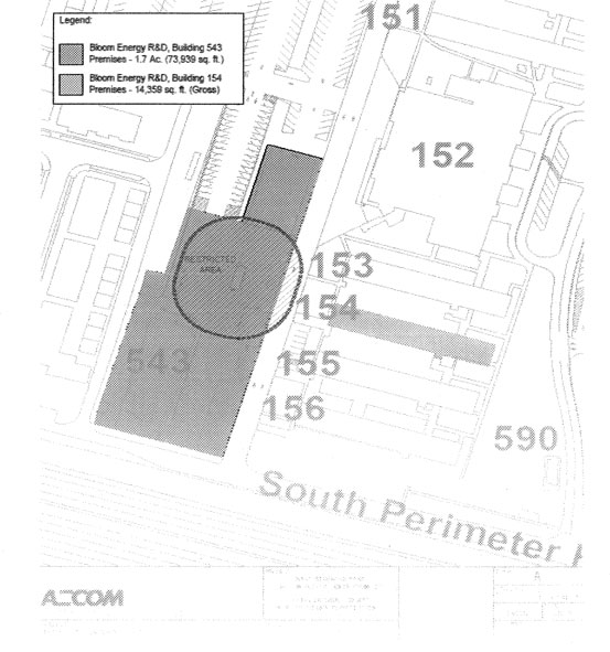
| BE 543 154 EUL Final 120511 | SAA2 – 402658 | |||
| -1- |
EXHIBIT A-l
Plans Outlining the Building 154 Premises
These site plans or floor plans are used solely for the purpose of identifying the approximate location and size of the Building 154 Premises. Building sizes, site dimensions, access, common and parking areas, and existing tenants and locations are subject to change at Landlord’s discretion.
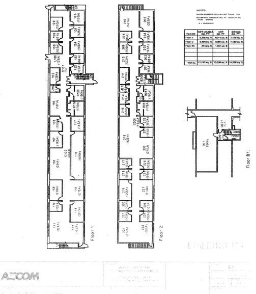
| BE 543 154 EUL Final 120511 | SAA2 – 402658 | |||
| -1- |
EXHIBIT B
Description of the TI Work
Painting
Replace carpets
New furniture and cabinets in break room
Install IT network system (Cisco switches and routers)
Install badge readers on external doors that will be tied into the Xxxx Security system
Install separate water meter
| BE 543 154 EUL Final 120511 | SAA2 – 402658 | |||
| -1- |
EXHIBIT C
Support Agreement
[Consists of three pages immediately following this page]
| BE 543 154 EUL Final 120511 | SAA2 – 402658 | |||
| -1- |
FIRST AMENDMENT TO NASA XXXX RESEARCH
CENTER ENHANCED USE LEASE
This First Amendment to NASA Xxxx Research Center Enhanced Use Lease (the “Amendment”) is made as of November 1, 2012 (the “Effective Date”), by and between the NATIONAL AERONAUTICS AND SPACE ADMINISTRATION, an Agency of the United States, acting by and through Xxxx Research Center located at Xxxxxxx Field, California (“Landlord”), and BLOOM ENERGY CORPORATION, a Delaware corporation (“Tenant”), with reference to the following facts:
X. Xxxxxxxx and Xxxxxx entered into that certain NASA Xxxx Research Center Enhanced Use Lease, dated as of December 5, 2011 (SAA2 - 402658) (the “Lease”). Each capitalized term used in this Amendment, but not defined herein, shall have the meaning ascribed to it in the Lease.
B. Tenant desires to construct a building (containing approximately 3,375 square feet of space) (such building, together with all other work related thereto as shown on the construction drawings for such building, is referred to collectively herein as the “Additional Building”) on the real property included within the Building 543 Premises. Xxxxxxxx is willing to allow Xxxxxx to construct the Additional Building on the terms and conditions of this Amendment.
X. Xxxxxxxx has informed Tenant that new agency guidance is being promulgated regarding the disposal of hazardous waste generated by tenants. The parties desire to revise the Lease to conform to such guidance.
NOW, THEREFORE, the parties agree as follows:
1. Construction of the Additional Building.
(a) Pursuant to section 7.1 of the Lease, Landlord hereby consents to Tenant’s construction of the Additional Building subject to the following conditions precedent, which must be satisfied or waived in writing by Landlord before construction of the Additional Building (or any work in connection therewith) can begin: (1) Landlord shall have approved a complete set of construction drawings for the Additional Building as required by section 7.1 of the Lease (including all other information required pursuant to section 7.1 of the Lease); (2) Tenant shall have paid to Landlord all fees and other amounts due to Landlord (if any) under the Lease, including the fee to issue the Permit (as defined below); and (3) Landlord’s Chief Building Official shall have issued to Tenant a construction permit for the Additional Building and to install a temporary construction trailer on the Building 543 Premises as more particularly described in section 1(j) of this Amendment (the “Permit”).
(b) Tenant shall: (i) commence construction of the Additional Building promptly after the date on which the Permit is issued to Tenant (the “Permit Issue Date”); (ii) diligently prosecute the same to completion; (iii) comply with all Applicable Laws; (iv) obtain all necessary permits and approvals other than the Permit; and (v) use its reasonable efforts to
| BE 543 154 EUL 1st Amend Final 110112 | SAA2 – 402658 | |||
| 1 |
complete the Additional Building as quickly as possible thereafter, which is expected to occur during the Construction Period (as defined below). During the Construction Period, Landlord has agreed to reduce the monthly Base Rent applicable to the Additional Building as set forth on the amended Basic Lease Information attached to this Amendment as Exhibit 1. If the Additional Building is not completed during the Construction Period, Tenant may continue to perform such work thereafter; provided, however, Tenant shall pay the full monthly Base Rent with respect to the Premises. As used in this Amendment, the phrase “Construction Period” means the period of time beginning on the Effective Date and ending on the earlier of: (1) the date on which NASA’s Fire Marshal completes a final inspection of the Additional Building and determines that the Additional Building is substantially complete; or (2) ninety (90) days following the Permit Issue Date.
(c) Xxxxxx does not intend to obtain secured financing in connection with the construction, use or occupancy of the Additional Building. Xxxxxx understands and agrees that Xxxxxxxx will not subordinate fee title to any financing.
(d) At all times while work on the Additional Building is being performed, and in addition to the insurance coverage required under the Lease, Tenant shall maintain comprehensive “all risk” or “special form” builder’s risk insurance, including vandalism and malicious mischief. Such builder’s risk insurance shall cover all portions of the Additional Building, all materials and equipment stored at the Premises or the Property by Tenant or its agents, employees, contractors, invitees or licensees (collectively, “Tenant’s Related Entities”), and all materials and equipment that are in the process of fabrication at the premises of any third party or that have been placed in due course of transit to the Premises when such fabrication or transit is at the risk of, or when title to or an insurable interest in such materials or equipment, has passed to Tenant or Tenant’s Related Entities (excluding any tools and equipment, and property owned by the employees of Tenant’s Related Entities). Such builder’s risk insurance shall be written on a completed value basis in an amount not less than the full estimated replacement cost of the Additional Building.
(e) Tenant shall perform all work in accordance with all Applicable Laws, the recommendations of Xxxxxx’s geotechnical, environmental, engineering and other construction consultants, and in a good and workmanlike manner using materials of a quality consistent with the nature of the other improvements on the Premises. Tenant shall not construct any buildings or other structures outside the boundaries of the Premises or on, over or above any utilities of Landlord within or crossing the Premises. Tenant shall not use any portion of the Property other than the Premises in connection with the construction of the Additional Building.
(f) Tenant shall prepare and maintain on the Premises (i) on a current basis during the construction of the Additional Building, annotated construction drawings showing clearly all substantive changes, revisions and substitutions during such period of construction, and (ii) upon the substantial completion of the Additional Building, as - built drawings showing clearly all changes, revisions and substitutions during the period of construction, including minor field changes and the final location of all mechanical equipment, utility lines, ducts, outlets, structural members, walls, partitions and other significant features of the work.
| BE 543 154 EUL 1st Amend Final 110112 | SAA2 – 402658 | |||
| 2 |
(g) All rights of Landlord to review, comment upon, approve, inspect or take any other action with respect to the Premises, the Additional Building or the design or construction thereof are specifically for the benefit of Landlord and no other party. No review, comment, approval or inspection, required or permitted by, of, or to Landlord hereunder shall give or be deemed to give Landlord any liability, responsibility or obligation for, in connection with, or with respect to, the design, demolition, construction, maintenance, repair, preservation, rehabilitation, reconstruction, restoration or operation of the Premises or the Additional Building, or the removal and/or remediation of any Hazardous Materials on, in or from the Premises, nor shall any such approval or inspection be deemed to relieve Tenant of the sole obligation and responsibility for the design, construction, maintenance, repair, preservation, rehabilitation, reconstruction, restoration, and operation of the Premises (including the Additional Building) and the removal and/or remediation of Hazardous Materials. Similarly, no inspection performed or not performed by Landlord under this Lease shall: (i) give or be deemed to give Landlord any responsibility or liability with respect to the thing inspected, the work or the prosecution thereof, or the design or construction of the work or any part thereof; (ii) constitute or be deemed to constitute a waiver of any of Tenant’s obligations or Tenant’s rights hereunder; or (iii) be construed as approval or acceptance of the thing inspected or the prosecution thereof, or the design or construction of the work or any part thereof.
(h) Tenant shall have no power to do any act or to make any contract that may create or be the foundation for any lien, mortgage or other encumbrance upon the reversion, fee interest or other estate of Landlord or of any interest of Landlord in the Premises. Tenant shall notify all of its contractors that Tenant does not own fee title to the Premises (or any other portion of the Property), and such contractors shall be instructed to record any preliminary notice or other document related to any mechanic’s or materialmen’s liens against only Xxxxxx’s leasehold interest in the Premises and not against fee title to the Property. At least ten (10) days before the date on which construction begins or materials are delivered, Tenant shall give written notice to Landlord of such date of commencement of construction or of the delivery of materials, as the case may be. Landlord shall then have the right to post and maintain on the Premises and other portions of the Property any notices that are required to protect Landlord and Landlord’s interest in the Property from any liens for work and labor performed or materials furnished in completing the Additional Building. Nothing in this Amendment or the Lease shall be deemed to be, or be construed in any way as constituting, the consent of or request by Xxxxxxxx, expressed or implied, by inference or otherwise, to any person, firm or corporation, for the performance of any labor or the furnishing of any materials for any construction, repairs, maintenance, replacement, alterations or redevelopment of or to the Premises or any part thereof, or as giving Tenant any right, power or authority to contract for or permit the rendering of any services or the furnishing of any materials that might in any way give rise to the right to file any lien against Landlord’s interest in the Premises.
(i) Tenant shall not suffer or permit any liens to stand against the Property or any part thereof by reason of any work, labor, services or materials done for, or supplied to, or claimed to have been done for or supplied to Tenant. Tenant shall keep the Property free and clear of any and all mechanics’, materialmen’s and other liens for work done, services performed, materials supplied or appliances used or furnished in or about the Premises in connection with any activities of Tenant on or about the Premises. If any such lien shall at any
| BE 543 154 EUL 1st Amend Final 110112 | SAA2 – 402658 | |||
| 3 |
time be filed, Tenant shall cause the same to be discharged of record within thirty (30) days prior to the date any such lien may be foreclosed upon. If Tenant fails to discharge or contest such lien within such period and such failure shall continue for a period of fifteen (15) days after notice by Landlord, then, in addition to any other right or remedy of Landlord, Landlord may, but shall not be obligated to, procure the discharge of the same either by paying the amount claimed to be due, by deposit in court, or by bonding. All amounts paid or deposited by Landlord for any of the aforesaid purposes, and all other expenses of Landlord and all necessary disbursements in connection therewith, in defending any such action or in procuring the discharge of such lien, shall become due and payable by Tenant to Landlord promptly upon written demand therefor.
(j) Provided that the Permit is issued to Tenant, Landlord hereby gives Tenant permission: (i) to use the Building 543 Premises during the Construction Period as a materials storage and staging area to construct the Additional Building; and (ii) to install on the Building 543 Premises a temporary construction trailer in connection with the construction of the Additional Building. Tenant shall remove the temporary construction trailer from the Property no later than the date which is thirty (30) days after NASA’s Fire Marshal completes a final inspection of the Additional Building and determines that the Additional Building is substantially complete.
(k) Tenant shall construct the Additional Building by engaging contractors that pay the prevailing wages in the area.
(l) Upon the expiration or earlier termination of the Lease, Tenant shall demolish and remove from the Property the Additional Building and all other improvements now or hereafter constructed in connection therewith (including, without limitation, the slab, foundation and other improvements on or under the ground surface) (collectively, the “Removal Work”). Xxxxxx agrees that if Xxxxxx fails to complete the Removal Work, and Landlord incurs any costs in connection therewith, Landlord may apply the Security Deposit to cover such costs.
2. Amendments of the Lease. As of the Effective Date, the parties hereby agree to amend the Lease as follows:
(a) The Basic Lease Information attached to the Lease is hereby deleted and replaced in its entirety with the Basic Lease Information attached to this Amendment as Exhibit 1. Among other things, the amended Basic Lease Information sets forth the monthly Base Rent to be paid during construction of the Additional Building and after its completion.
(b) The site plan depicting the Building 543 Premises attached to the Lease as Exhibit A is hereby deleted and replaced with the site depicting the Building 543 Premises (including the proposed location of the Additional Building) attached to this Amendment as Exhibit 2.
(c) The Support Agreement attached to the Lease as Exhibit C is hereby deleted and replaced with the Support Agreement attached to this Amendment as Exhibit 3.
| BE 543 154 EUL 1st Amend Final 110112 | SAA2 – 402658 | |||
| 4 |
(d) Section 4.3 of the Lease is hereby deleted and restated in its entirety as follows:
“4.3 Environmental Requirements. Tenant understands that the Property is underlain by a plume of contaminated groundwater that comprises two Superfund sites: the former Naval Air Station Xxxxxxx Field; and the Middlefield-Xxxxx-Xxxxxxx site. Tenant understands that the groundwater is contaminated with solvents and petroleum hydrocarbons. Tenant hereby acknowledges receipt of the environmental reports listed on attached Exhibit D. Tenant hereby agrees that: (a) Tenant shall not conduct, or permit to be conducted, on the Premises any activity which is not a Permitted Activity; (b) Tenant shall not use, store or otherwise handle, or permit any use, storage or other handling of, any Hazardous Material which is not a Permitted Material on or about the Premises; (c) Tenant shall obtain and maintain in effect all permits and licenses required pursuant to any Environmental Law for Tenant’s activities on the Premises, and Tenant shall at all times comply with all applicable Environmental Law; (d) Tenant shall not engage in the storage, treatment or disposal on or about the Premises of any Hazardous Material except for any temporary accumulation of waste generated in the course of Permitted Activities; (e) Tenant shall not install any aboveground or underground storage tank or any subsurface lines for the storage or transfer of any Hazardous Material, except in accordance with Environmental Law, and Tenant shall store all Hazardous Materials in a manner that protects the Premises, the Buildings, the Property and the environment from accidental spills and releases; (f) Tenant shall not cause any (and shall not allow any third party other than Landlord on the Premises during the Term to) release of any Hazardous Material or any condition of pollution or nuisance on or about the Premises, whether affecting surface water or groundwater, air, the land or the subsurface environment; (g) Tenant shall promptly remove from the Premises any Hazardous Material introduced, or permitted to be introduced, onto the Premises by Tenant which is not a Permitted Material and, on or before the date Tenant ceases to occupy the Premises, Tenant shall remove from the Premises all Hazardous Materials and all Permitted Materials handled by or permitted on the Premises by Tenant; (h) if any release of a Hazardous Material to the environment, or any condition of pollution or nuisance, occurs on or about or beneath the Premises or either Building as a result of any act of Tenant or its agents, employees, contractors, invitees or licensees, Tenant, at Tenant’s sole cost and expense, shall promptly undertake all remedial measures required to clean up and xxxxx or otherwise respond to the release, pollution or nuisance in accordance with all applicable Environmental Law; and (i) Tenant shall obtain its own identification number from the United States Environmental Protection Agency (and all applicable state and local agencies) and shall store, handle, transport and dispose of all hazardous waste generated by Tenant
| BE 543 154 EUL 1st Amend Final 110112 | SAA2 – 402658 | |||
| 5 |
on or about the Premises in accordance with all applicable Environmental Law. Landlord and Landlord’s representatives shall have the right, but not the obligation, to enter the Premises at any reasonable time for the purpose of inspecting the storage, use and handling of any Hazardous Material on the Premises in order to determine Tenant’s compliance with the requirements of this Lease and applicable Environmental Law. If Landlord gives written notice to Tenant that Tenant’s use, storage or handling of any Hazardous Material on the Premises may not comply with this Lease or applicable Environmental Law, Tenant shall correct any such violation within five (5) days after Xxxxxx’s receipt of such notice from Landlord to the extent required by Environmental Laws. Tenant shall indemnify and defend Landlord against and hold Landlord harmless from all claims, demands, actions, judgments, liabilities, costs, expenses, losses, damages, penalties, fines and obligations of any nature (including reasonable attorneys’ fees and disbursements incurred in the investigation, defense or settlement of claims) that Landlord may incur as a result of, or in connection with, claims arising from the presence, use, storage, transportation, treatment, disposal, release or other handling, on or about or beneath the Premises, of any Hazardous Material existing on or about or beneath the Premises caused by Tenant or its agents, employees, contractors, invitees or licensees (collectively ‘Tenant Contamination’). Landlord hereby agrees to release Tenant from, and shall not charge Tenant for, any liabilities, costs, expenses, losses, damages, penalties, fines or obligations of any nature as a result of, or in connection with any Hazardous Materials existing at the Property that are not Tenant Contamination, except to the extent that Tenant or its employees, agents, contractors or invitees exacerbates or causes a release of any such existing Hazardous Materials. Except for the storage, handling, transportation (including execution of manifests) and disposal of hazardous waste generated by Tenant on or about the Premises, Tenant’s activities that comply with the permitted use of the Premises set forth in the Basic Lease Information will be included in NASA’s sitewide permits and plans, as applicable, such as the Spill Prevention Control and Countermeasures Plan, the Storm Water Pollution Prevention Plan, the above ground storage tank statement, the Sunnyvale Industrial Waste Water permit, the Environmental Resources Document, and the Integrated Natural Resources Management Plan. Coverage in these and other sitewide plans is included in the cost of ISP Services (as defined in section 6.1). Tenant shall promptly supply information to the NASA Environmental Office (Code JQ) that is needed to complete these documents, and comply with the conditions of these permits. Tenant, at its sole cost, is responsible for obtaining an identification number from the United States Environmental Protection Agency, and obtaining hazardous materials storage permits and air permits required by Environmental Law for Tenant’s use of the Premises. The liability of Tenant under this section 4.3 shall survive the termination of this Lease with respect to acts or omissions that occur before such termination.”
| BE 543 154 EUL 1st Amend Final 110112 | SAA2 – 402658 | |||
| 6 |
(e) Section 8.2(d) of the Lease is hereby amended by adding the following sentence immediately before the last section of section 8.2(d):
“The Full Insurable Replacement Value of the Additional Building initially shall be four hundred fifty thousand dollars ($450,000.00).”
3. No Other Amendment; Conflicts. Except as set forth in this Amendment, the provisions of the Lease remain in full force. If the provisions of this Amendment conflict with the provisions of the Lease, then the provisions of this Amendment shall prevail.
IN WITNESS WHEREOF, Xxxxxxxx and Xxxxxx have executed this Amendment as of the Effective Date.
| Tenant: | Landlord: | |||||||
| BLOOM ENERGY CORPORATION, a Delaware corporation |
NATIONAL AERONAUTICS AND SPACE ADMINISTRATION, an Agency of the United States | |||||||
| By | /s/ Xxxxxxx X. Xxxxx | By | /s/ S. Xxxx Xxxxxx | |||||
| Xxxxxxx X. Xxxxx Chief Financial Officer |
X. Xxxx Xxxxxx Director, Xxxx Research Center | |||||||
| BE 543 154 EUL 1st Amend Final 110112 | SAA2 – 402658 | |||
| 7 |
EXHIBIT 1 TO FIRST AMENDMENT
NASA XXXX RESEARCH CENTER
ENHANCED USE LEASE
Amended Basic Lease Information
Date: November 1, 2012.
Landlord: NATIONAL AERONAUTICS AND SPACE ADMINISTRATION, an Agency of the United States, Xxxx Research Center located at Xxxxxxx Field, California.
Tenant: BLOOM ENERGY CORPORATION, a Delaware corporation.
Premises (section 1.1): (a) The parcel of real property outlined in Exhibit A, containing approximately 73,939 square feet (more or less) of land area, including Building 543 (containing approximately 9,166 square feet (more or less) of building space (“Building 543”)) and all other improvements owned by Landlord thereon (collectively, the “Building 543 Premises”); and (b) all of the space in Building 154 (“Building 154”) outlined in Exhibit A-1, containing approximately 14,359 square feet (more or less) of building area (the “Building 154 Premises”). The Building 543 Premises and the Building 154 Premises are located at NASA Xxxx Research Center, Xxxxxxx Field, California. A site plan showing the locations of the Building 543 Premises and the Building 154 Premises is attached hereto as Exhibit A. Tenant intends to construct an additional building on the Building 543 Premises (the “Additional Building”) in the location depicted on such site plan. Building 543, the Additional Building and Building 154 are individually referred to herein as a “Building” and are collectively referred to herein as the “Buildings.”
Property (section 1.1): The land, the buildings and other improvements known as NASA Xxxx Research Center, Xxxxxxx Field, California 94035-1000.
Term (section 2.1): Approximately three (3) years.
Commencement Date (section 2.1): December 16, 2011.
Expiration Date (section 2.1): December 31, 2014.
Monthly Base Rent (dollars per month) (section 3.1): $42,351.61; provided, however, during the period beginning on November 1, 2012 and ending on January 30, 2013 during which Tenant intends to construct the Additional Building, the monthly Base Rent for the Premises shall be reduced to $41,643.86.
Security Deposit (section 3.3): $40,500.00.
| BE 543 154 EUL 1st Amend Final 110112 | SAA2 – 402658 | |||
| i |
| Rent Payment Address (section 3.7): | NASA Shared Service Center (NSSC)- FMD Accounts Receivable Attn: For the Accounts of Xxxx Research Center (Agreement #SAA2-402658) Bldg. 0000, X Xxxx Xxxxxxx Xxxxx Xxxxxx, XX 00000 |
Permitted Use of the Premises (section 4.1): Bloom Energy will use and occupy the Building 543 Premises solely for research and development, and testing, including as its research laboratory and to test its products. Bloom Energy will use and occupy the Building 154 Premises solely for office purposes; provided, however, Bloom Energy may use rooms 124, 125, 126, 128, 129 and 130 for minor assembly of wiring harnesses and piping.
| Landlord’s Address (section 14.1): | NASA Xxxx Research Center Xx. Xxxxxxx X. Xxxxxx, Mail Stop 204 – 2 Bldg. 204, Rm 215 P.O. Box 1 Xxxxxxx Field, CA 94035-0001 | |
| Tenant’s Address (section 14.1): | Bloom Energy Corporation 0000 Xxxxxxx Xxxxx Xxxxxxxxx, XX 00000 Attn: Xx. Xxxxxxx X. Xxxxx | |
Exhibit A – Site Plan; Plan Outlining the Building 543 Premises
Exhibit A-1 – Plans Outlining the Building 154 Premises
Exhibit B – Description of the TI Work
Exhibit C – Support Agreement
Exhibit D – List of Environmental Reports
The foregoing Basic Lease Information is incorporated in and made a part of the Lease to which it is attached. If there is any conflict between the Basic Lease Information and the Lease, the Basic Lease Information shall control.
| Tenant:
BLOOM ENERGY CORPORATION, a Delaware corporation |
Landlord:
NATIONAL AERONAUTICS AND SPACE ADMINISTRATION, an Agency of the United States | |||||||
| By | /s/ Xxxxxxx X. Xxxxx | By | /s/ S. Xxxx Xxxxxx | |||||
| Xxxxxxx X. Xxxxx Chief Financial Officer |
X. Xxxx Xxxxxx Director, Xxxx Research Center | |||||||
| BE 543 154 EUL 1st Amend Final 110112 | SAA2 – 402658 | |||
| ii |
EXHIBIT 2 TO FIRST AMENDMENT
Revised Site Plan; Plan Outlining the Building 543 Premises
(Supersedes Exhibit A to Lease)
This site plan is used solely for the purpose of identifying the approximate location and size of the Premises, including the approximate location and size of the Building 543 Premises and the Restricted Area. Building sizes, site dimensions, access, common and parking areas, and existing tenants and locations are subject to change at Landlord’s discretion.
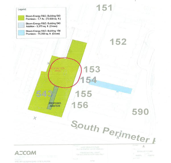
| BE 543 154 EUL 1st Amend Final 110112 | SAA2 – 402658 | |||
| 1 |
EXHIBIT 3 TO FIRST AMENDMENT
Revised Support Agreement
(Supersedes Exhibit C to Lease)
[Consists of three pages immediately following this page]
| BE 543 154 EUL 1st Amend Final 110112 | SAA2 – 402658 | |||
| 1 |
SECOND AMENDMENT TO NASA XXXX RESEARCH
CENTER ENHANCED USE LEASE
This Second Amendment to NASA Xxxx Research Center Enhanced Use Lease (the “Amendment”) is made as of August 25. 2014 (the “Effective Date”), by and between the NATIONAL AERONAUTICS AND SPACE ADMINISTRATION, an Agency of the United States, acting by and through Xxxx Research Center located at Xxxxxxx Field, California (“Landlord”), and BLOOM ENERGY CORPORATION, a Delaware corporation (“Tenant”), with reference to the following facts:
X. Xxxxxxxx and Xxxxxx entered into that certain NASA Xxxx Research Center Enhanced Use Lease, dated as of December 5, 2011 (SAA2 - 402658) (the “Lease”) Each capitalized term used in this Amendment, but not defined herein, shall have the meaning ascribed to it in the Lease.
B. Tenant duly requested, and Landlord duly approved Xxxxxx’s request to extend the Term as provided in section 2.1(b) of the Original Lease. Xxxxxx has requested that Xxxxxxxx agree to extend the term for two (2) years. Xxxxxxxx is willing to extend the Term on the terms and conditions of this Amendment.
NOW, THEREFORE, the parties agree as follows:
1. Amendments of the Lease. As of the Effective Date, the parties hereby agree to amend the Lease as follows:
(a) The Basic Lease Information attached to the Lease is hereby deleted and replaced in its entirety with the Basic Lease Information attached to this Amendment as Exhibit 1. Among other things, the amended Basic Lease Information reflects (1) the extension of the Term such that the Expiration Date is December 31, 2016. (2) the amount of monthly Gross Rent as of the Effective Date.
2. No Other Amendment; Conflicts. Except as set forth in this Amendment, the provisions of the Original Lease remain in full force. If the provisions of this Amendment conflict with the provisions of the Original Lease, then the provisions of this Amendment shall prevail.
| BE 543 154 EUL 2nd Amend Final 082514 | SAA2 – 402658 | |||
| 1 |
IN WITNESS WHEREOF. Xxxxxxxx and Xxxxxx have executed this Amendment as of the Effective Date.
| Tenant:
BLOOM ENERGY CORPORATION, a Delaware corporation |
Landlord:
NATIONAL AERONAUTICS AND SPACE ADMINISTRATION, an Agency of the United States | |||||||
| By | /s/ Xxxxxxx X. Xxxxx | By | /s/ S. Xxxx Xxxxxx | |||||
| Xxxxxxx X. Xxxxx Chief Financial Officer |
X. Xxxx Xxxxxx Director, Xxxx Research Center | |||||||
| BE 543 154 EUL 2nd Amend Final 082514 | SAA2 – 402658 | |||
| 2 |
EXHIBIT 1 TO SECOND AMENDMENT
NASA XXXX RESEARCH CENTER
ENHANCED USE LEASE
Amended Basic Lease Information
Date: August 25, 2014.
Landlord: NATIONAL AERONAUTICS AND SPACE ADMINISTRATION, an Agency of the United States. Xxxx Research Center located at Xxxxxxx Field, California.
Tenant: BLOOM ENERGY CORPORATION, a Delaware corporation.
Premises (section 1.1): (a) The parcel of real property outlined in Exhibit A, containing approximately 73,939 square feet (more or less) of land area, including Building 543 (containing approximately 9,166 square feet (more or less) of building space (“Building 543”)) and all other improvements owned by Landlord thereon (collectively, the “Building 543 Premises”); and (b) all of the space in Building 154 (“Building 154”) outlined in Exhibit A-1, containing approximately 14,359 square feet (more or less) of building area (the “Building 154 Premises”). The Building 543 Premises and the Building 154 Premises are located at NASA Xxxx Research Center, Xxxxxxx Field, California. A site plan showing the locations of the Building 543 Premises and the Building 154 Premises is attached hereto as Exhibit A. Tenant constructed an additional building (approximately 3,375 square feet (more or less) on the Building 543 Premises (the “Additional Building”) in the location depicted on such site plan. Building 543, the Additional Building and Building 154 are individually referred to herein as a “Building” and are collectively referred to herein as the “Buildings.”
Property (section 1.1): The land, the buildings and other improvements known as NASA Xxxx Research Center, Xxxxxxx Field, California 94035-1000.
Term (section 2.1): Approximately five (5) years.
Commencement Date (section 2.1): December 16, 2011.
Expiration Date (section 2.1): December 31, 2016.
Monthly Base Rent (dollars per month) (section 3.1): $31,793.11 (based on $1.02 per square foot per month for Bldg. 543, (b) $1.04 per square foot per month for Bldg. 154, (c) $0.17 per square foot per month for additional land (approximately 44.179 sf) which is the remainder of the total parcel less the normalized parcel for Bldg. 543).
Security Deposit (section 3.3): $40,500.00.
| BE 543 154 EUL 2nd Amend Final 082514 | SAA2 – 402658 | |||
| i |
| Rent Payment Address (section 3.7): | NASA Shared Service Center (NSSC)- FMD Accounts Receivable Attn: For the Accounts of Xxxx Research Center (Agreement #SAA2-402658) Bldg. 0000, X Xxxx Xxxxxxx Xxxxx Xxxxxx, XX 00000 |
Permitted Use of the Premises (section 4.1): Bloom Energy will use and occupy the Building 543 Premises solely for research and development, and testing, including as its research laboratory and to test its products. Bloom Energy will use and occupy the Building 154 Premises solely for office purposes; provided, however, Bloom Energy may use rooms 124, 125, 126, 128, 129 and 130 for minor assembly of wiring harnesses and piping.
| Landlord’s Address (section 14.1): | NASA Xxxx Research Center Xx. Xxxxxxx X. Xxxxxx, Mail Stop 204 2 Bldg. 204, Rm 215 P.O. Box 1 Xxxxxxx Field, CA 94035-0001 | |
| Tenant’s Address (section 14.1): | Bloom Energy Corporation 0000 Xxxxxxx Xxxxx Xxxxxxxxx, XX 00000 Attn: Xx. Xxxxxxx X. Xxxxx | |
Exhibit A – Site Plan; Plan Outlining the Building 543 Premises
Exhibit A-1 – Plans Outlining the Building 154 Premises
Exhibit B – Description of the TI Work
Exhibit C – Support Agreement
Exhibit D – List of Environmental Reports
The foregoing Basic Lease Information is incorporated in and made a part of the Lease to which it is attached. If there is any conflict between the Basic Lease Information and the Lease, the Basic Lease Information shall control.
| Tenant:
BLOOM ENERGY CORPORATION, a Delaware corporation |
Landlord:
NATIONAL AERONAUTICS AND SPACE ADMINISTRATION, an Agency of the United States | |||||||
| By | /s/ Xxxxxxx X. Xxxxx | By | /s/ S. Xxxx Xxxxxx | |||||
| Xxxxxxx X. Xxxxx Chief Financial Officer |
X. Xxxx Xxxxxx Director, Xxxx Research Center | |||||||
| BE 543 154 EUL 2nd Amend Final 082514 | SAA2 – 402658 | |||
| ii |
EXHIBIT 2 TO SECOND AMENDMENT
Revised Site Plan; Plan Outlining the Building 543 Premises
(Supersedes Exhibit A to Lease)
This site plan is used solely for the purpose of identifying the approximate location and size of the Premises, including the approximate location and size of the Building 543 Premises and the Restricted Area. Building sizes, site dimensions, access, common and parking areas, and existing tenants and locations are subject to change at Landlord’s discretion.
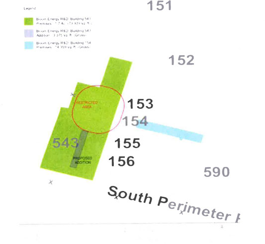
| BE 543 154 EUL 2nd Amend Final 082514 | SAA2 – 402658 | |||
| 1 |
EXHIBIT 3 TO SECOND AMENDMENT
Revised Support Agreement
(Supersedes Exhibit C to Lease)
| BE 543 154 EUL 2nd Amend Final 082514 | SAA2 – 402658 | |||
| 2 |
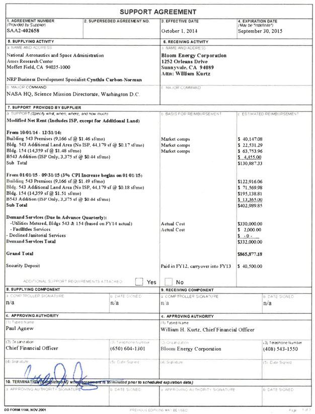
SUPPORT AGREEMENT 1 agreement number (Provided by Suppler SAA2-402658 2 superseded agreement no. 6. SUPPLYING ACTIVITY 3 name and ADDRESS National Aeronautics and Space Administration Xxxx Research Center Morten Field, CA 94035-1000 NRP Business Development Specialist: Xxxxxxx Carbon-Xxxxxx D major COMMAND NASA HQ, Science Mission Directorate, Washington DC. 3 effective date October 1. 2014 4. expiration date (May be ‘indefinite’) September 30, 2015 6. RECEIVING ACTIVITY a name AND ADDRESS Bloom Energy Corporation 0000 Xxxxxxx Xxxxx Xxxxxxxxx, XX 00000 Attn: Xxxxxxx Xxxxx C MAJOR COMMAND 7. SUPPORT PROVIDED BY SUPPLIER a SUPPOR (Specify what, when, where, and how much) Modified Net Rent (Includes ISP, except for Additional Land) From 10/01/14 - 12/31/14: Building 543 Premises (9,166 sf@ $1.46 sf/mo) Bldg. 543 Additional Land Area (No ISP, 44,179 sf @ $0.17 sf/mo) Bldg. 154 (14,359 sf @ $1.48 sf/mo) B543 Addition (ISP Only, 3,375 sf @ $0,44 sf/mo) Sub Total From 01/01/15 09/31/15 (3% CPI Increase begins on 01 01/15) Building 543 Premises (9,166 sf @ $1.49 sf/mo) Bidg. 543 Additional Land Area (No ISP, 44.179 sf @ $0.18 sf/mo) Bldg. 154 (14,359 sf @ $1.51 sf/mo) B543 Addition (ISP Only, 3,375 sf (@ $0,44 sf/mo) Sub Total Demand Services (Due in Advance Quarterly): -Utilities Metered, Bldgs 543 & 154 (based on FY14 actual) Facilities Services - Declined Janitorial Services Demand Services Total Grand Total Security Deposit ADDITIONAL SUPPORT REQUIREMENTS ATTACHED Market comps Market comps Market comps C BASIS FOR REIMBURSEMENT C ESTIMATED REIMBURSEMENT $ 40,147.08 $ 22,531.29 $ 63,753.96 $ 4,455.00 $130,88733 $122,916.06 $ 71,569.98 $195,138.81 $ 13,365.00 Actual Cost Actual Cost $402,989.85 $330,000.00 $ 2,000 00 $ -0- Yes $332,000.00 $865,877.18 Paid in FY12, carryover into FY13 $ 40,500.00 No S. SUPPLYING COMPONENT a COMPTROLLER SIGNATURE n/a b DATE SIGNED n/a c. APPROVING AUTHORITY (1) Typed Name Xxxx Xxxxx (2) Organization Chief Financial Officer (4) Signature 10. TERMINATION is terminated pnor to scheduled expiration data) (3) Telephone Number (000) 000-0000 (5) Date Signed 9. RECEIVING COMPONENT a COMPTROLLER SIGNATURE n/a b DATE SIGNED n/a c. APPROVING AUTHORITY (1) Typed Name Xxxxxxx X. Xxxxx. Chief Financial Officer (2) Organization Bloom Energy Corporation (4) Signature (3) Telephone Number (000) 000-0000 (5) Date Signed 3 APPROVING AUTHORITY SIGNATURE D DATE SIGNED a APPROVING AUTHORITY SIGNATURE D DATE SIGNED 00 FORM 1144, NOV 2001 PREVIOUS EOTIONS MAY BE USED Page 1 of 3
11. GENERAL PROVISIONS (Complete blank spaces and add additional general provision as appropriate e.g. exceptions to printed provisions, additional paths to this agreement, billing and reimbursement instructions) a. The receiving components will provide the supplying component projections of requested support (significant changes in the receiving components support requirements should be submitted to the supplying component in a manner that will permit timely modification of resources requirements) b. It is the responsibility of supplying component to bring any required change in support to the attention of prior to changing or cancelling support c. The component providing reimbursable support in this agreement will submit statements of costs to d. All rates expressing the unit cost of services provided in this agreement are base on current rates which may be subject to change for uncontrollable reasons, such as legislation, DoD directives, and commercial utility rate increases The receiver will be notified immediately of such rate changes that must be passed through to the support receivers e. This agreement may be cancelled at any time by mutual consent of the parties concerned This agreement may also be canceled by either party upon giving at least 180 days written notice to the other party f. In case of mobilization or other emergency this agreement remain in force only within supplier’s capabilities ADDITIONAL SUPPORT REQUIERMENTS ATTACHED Yes No 12. SPACIFIC PROVISION (As a appropriate e.g. location n and size of occupied facilities, unique support and receiver responsibilities conditions, requirements, quantity standards, and catena for measurement/ reimbursement of unique requirements ) ADDITONAL SUPPORT REQUIREMENTS ATTACHED Yes No DD FORM 1144 MOV 2001 PREVIOUS EDITIONS MAY BE USED Page 2 of 3
| 13. ADDITIONAL PROVISIONS (Use this space to continue general and/or specific provisions as needed)
| ||||
| DD FORM 1144, NOV 2001 | PREVIOUS EDITIONS MAY BE USED | Page 3 of 3 | ||
Revised Human Health Risk Assessment NASA Research Park
Xxxxxxx Field, California
MACTEC
Revised Human Health Risk Assessment NASA Research Park
Xxxxxxx Field, California
Prepared for
PAl/ISSi
NASA Xxxx Research Center Xxxxxxx Field, California 94035-1100
MACTEC Project No. 56042 3.6
Xxxxx Xxxxxxx, Ph.D.
Principal Environmental Scientist
Xxxxxxx Xxxxxxxx
Staff Environment Scientist
July 28, 2003
Engineering and Consulting
MACTEC, Inc. 00 Xxxxxxx Xxxxx
Novato, CA 94949 - (000) 000-0000
2
Revised Human Health Risk Assessment NASA Research Park
Xxxxxxx Field, California
MACTEC Project No. 56042 3.6
This document was prepared by MACTEC Engineering and Consulting, Inc. (MACTEC, formerly Xxxxxxx ESE, Inc.), at the direction of PAI/ISSi for the sole use of PAI/ISSi the only intended beneficiaries of this work. No other party should rely on the information contained herein without the prior written consent of PAI/XXXx and MACTEC. This report and the interpretations, conclusions, and recommendations contained within are based in part on information presented in other documents that are cited in the text and listed in the references. Therefore, this report is subject to the limitations and qualifications presented in the referenced documents.
3
CONTENTS
| LIST OF ACRONYMS |
7 | |||||
| 1.0 |
INTRODUCTION |
9 | ||||
| 2.0 |
BACKGROUND |
11 | ||||
| 2.1 |
Physical Setting |
11 | ||||
| 2.2 |
Groundwater Contamination |
11 | ||||
| 2.3 |
Soil Contamination |
12 | ||||
| 2.4 |
Previous Risk Assessment Evaluations |
12 | ||||
| 3.0 |
DATA EVALUATION AND IDENTIFICATION OF CHEMICALS OF POIBNTIAL CONCERN |
14 | ||||
| 3.1 |
Areas Defined for Evaluation of Risk |
14 | ||||
| 3.2 |
Data Evaluation |
14 | ||||
| 3.3 |
COPC Selection |
15 | ||||
| 3.4 |
Background Evaluation of Air Concentration |
16 | ||||
| 4.0 |
EXPOSURE ASSESSMENT |
17 | ||||
| 4.1 |
Exposure Setting and Land Use |
17 | ||||
| 4.2 |
Identification of Receptors and Pathways |
17 | ||||
| 4.3 |
Potential Receptors |
18 | ||||
| 4.4 |
Exposure Pathways |
18 | ||||
| 4.5 |
Conceptual Site Models |
19 | ||||
| 4.6 |
Exposure Point Concentrations |
19 | ||||
| 4.7 |
Chemical Intake Estimates |
20 | ||||
| 4.7.1 |
General Exposure Assumptions |
21 | ||||
| 4.7.2 |
Exposure Parameters and Equations for Dermal Contact with Groundwater |
21 | ||||
| 4.7.3 |
Groundwater Volatilization Model |
22 | ||||
| 4.7.3.l |
Differences between Draft Addendum and Revised Final HHRA |
24 | ||||
| 4.7.4 |
Exposure Parameters and Equations for Inhalation of Volatiles from Groundwater |
25 | ||||
| 5.0 |
TOXICITY ASSESSMENT |
26 | ||||
| 5.1 |
Noncarcinogenic Toxicity Criteria |
26 | ||||
| 5.2 |
Carcinogenic Toxicity Criteria |
27 | ||||
| 5.3 |
Toxicity Criteria for the COPCs |
29 | ||||
| 6.0 |
RISK CHARACTERIZATION |
35 | ||||
| 6.1 |
Noncarcinogenic Hazard |
35 | ||||
| 6.2 |
Cancer Risks |
36 | ||||
| 6.3 |
Risk Characterization Results |
37 | ||||
| 6.3.l |
Risk Characterization Summary |
38 | ||||
| 6.3.1.1 |
Differences between Draft Addendum and Revised HHRA |
41 | ||||
| 6.3.2 |
Risk Estimated from Groundwater Volatilization Model |
41 | ||||
| 6.3.3 |
Risk Estimated from Air Measurements |
42 | ||||
| 6.4 |
Soil Target Cleanup Levels |
44 | ||||
| 7.0 |
UNCERTAINTY EVALUATION |
45 | ||||
| 7.1 |
Toxicity Criteria and Factors |
45 | ||||
| 7.2 |
Exposure Pathways and Parameters |
45 | ||||
| 7.3 |
Laboratory and Sampling Results |
46 | ||||
| 7.4 |
Site Target Cleanup Levels |
46 | ||||
4
| 7.5 |
Site Air Concentration Measurements |
46 | ||||
| 7.6 |
Flux Measurements |
47 | ||||
| 7.7 |
Calculation of Modeled Airborne VOC Concentrations |
48 | ||||
| 7.8 |
Volatilization Model |
48 | ||||
| 7.9 |
1,1-DCE Carcinogenicity Assessment |
49 | ||||
| 7.10 |
TCE Health Risk Assessment |
49 | ||||
| 7.11 |
Benzene Health Risk Assessment |
50 | ||||
| 7.12 |
Factoring Out Vinyl Chloride Concentrations |
50 | ||||
| 8.0 |
SUMMARY AND CONCLUSIONS |
50 | ||||
| 9.0 |
LITERATURE CITED |
54 | ||||
| TABLES |
||||||
| 1 |
Groundwater Xxxxx Sampled |
|||||
| 2 |
Statistical Data Summary of Chemicals in Groundwater |
|||||
| 3 |
Locations of Air Samples Taken at NRP |
|||||
| 4 |
Statistical Data Summary of Chemicals in Air |
|||||
| 5 |
COPCs for Groundwater and Air |
|||||
| 6 |
Statistical Data Summary for Chemicals in Background Air |
|||||
| 7 |
Exposure Parameters for a Construction Worker |
|||||
| 8 |
Exposure Parameters for an Indoor Worker |
|||||
| 9 |
Exposure Parameters for Adult and Child Residents |
|||||
| 10 |
Exposure Parameters for 30 yr Residential Receptor |
|||||
| 11 |
Chemical Specific Derma) Factors |
|||||
| 12 |
Site-Specific Soil and Groundwater Characteristics |
|||||
| 13 |
Chemical Physical Properties |
|||||
| 14 |
Volatilization Model Parameters |
|||||
| 15 |
Toxicity Criteria for COPCs |
|||||
| 16 |
Construction Worker Receptor; Risks and Hazards Estimated from Groundwater Concentrations |
|||||
| 17 |
Indoor Worker Receptor; Risks and Hazards Estimated from Groundwater Concentrations |
|||||
| 18 |
Adult Resident (10 yr RME) Receptor; Risks and Hazards Estimated from Groundwater Concentrations |
|||||
| 19 |
Child Resident (10 yr RME) Receptor; Risks and Hazards Estimated from Groundwater Concentrations |
|||||
| 20 |
RME 30 yr Residential Receptor; Risks and Hazards Estimated from Groundwater Concentrations |
|||||
| 21 |
Construction Worker Receptor; Risks and Hazards Estimated from Measured Air Concentrations |
|||||
| 22 |
Indoor Worker Receptor; Risks and Hazards Estimated from Measured Air Concentrations |
|||||
| 23 |
Adult Resident (10 yr RME) Receptor; Risks and Hazards Estimated from Measured Air Concentrations |
|||||
| 24 |
Child Resident (10 yr RME) Receptor; Risks and Hazards Estimated from Measured Air Concentrations |
|||||
5
| 25 |
RME 30 yr Residential Receptor; Risks and Hazards Estimated from Measured Air Concentrations |
|||||
| 26 |
Background Risks and Hazards Estimated from Measured BAAQMD Air Concentrations |
|||||
| 27 |
Comparison of Cleanup Levels for Soil |
|||||
| PLATES |
| |||||
| l |
Property and Parcel Location Map |
|||||
| 2 |
Well Sample Location Map |
|||||
| 3 |
Air Sample Location Map |
|||||
| 4 |
Construction RME Risk |
|||||
| 5 |
Construction CTE Risk |
|||||
| 6 |
Construction RME HI |
|||||
| 7 |
Construction CTE HI |
|||||
| 8 |
Indoor Worker RME Risk |
|||||
| 9 |
Indoor Worker CTE Risk |
|||||
| 10 |
Indoor Worker RME HI |
|||||
| 11 |
Indoor Worker CTE HI |
|||||
| 12 |
Adult Resident (10 yr) RME Risk |
|||||
| 13 |
Adult Resident (5 yr) CTE Risk |
|||||
| 14 |
Adult Resident (10 yr) RME HI |
|||||
| 15 |
Adult Resident (5 yr) CTE HI |
|||||
| 16 |
Child Resident (10 yr) RME Risk |
|||||
| 17 |
Child Resident (5 yr) CTE Risk |
|||||
| 18 |
Child Resident (10 yr) RME HI |
|||||
| 19 |
Child Resident (5 yr) CTE HI |
|||||
| 20 |
Resident (30 yr) RME Risk |
|||||
| 21 |
Resident, Adult (24 yr) HI |
|||||
| 22 |
Resident, Child (6 yr) HI |
|||||
| FIGURES |
||||||
| Conceptual Site Model |
||||||
| APPENDIXES |
||||||
| A |
SURFACE FLUX MEASUREMENT PROGRAM |
|||||
| B |
CALCULATION OF EXPOSURE POINT CONCENTRATIONS GROUNDWATER DATA |
|||||
| D |
AIR DATA |
|||||
| E |
INTERMEDIATE CALCULATIONS FOR THE GROUNDWATER TO AIR VOLATILIZATION MODEL |
|||||
| F |
RESPONSES TO COMMENTS |
|||||
6
| DISTRIBUTION | ||
| LIST OF ACRONYMS | ||
| 1,1-DCA |
1,1-Dichloroethane | |
| 1,1-DCE |
1,1-Dichloroethylene, also called 1,1-Dichloroethene | |
| 1,2-DCA |
1,2-Dichloroethane | |
| 1,1,1-TCA |
1,1,1 -Trichloroethane | |
| ABS |
Dermal-Absorption factor | |
| ADD |
Average Daily Dose | |
| AF |
Soil-Adherence Factor | |
| ASTM |
American Society for Testing and Materials | |
| AT |
Averaging Time | |
| B[a]P |
Benzo(a)pyrene | |
| BW |
Body Weight | |
| BTEX |
Benzene, Toluene, Ethyl benzene, and Xylenes | |
| Cal/EPA |
California Environmental Protection Agency | |
| cis-1,2-DCE |
cis-1,2-Dichloroethylene, also called cis-1,2-Dichloroethene | |
| cfm |
cubic feet per minute | |
| Cgw |
Exposure point concentration (EPC) in groundwater | |
| COPC |
Chemical of Potential Concern | |
| CSM |
Conceptual Site Model | |
| CTE |
Central Tendency Estimate | |
| DNA |
Deoxyribonucleic acid, commonly called DNA with further description | |
| DTSC |
Department of Toxic Substances Control | |
| EA |
Endangerment Assessment | |
| EBS |
Environmental Baseline Survey | |
| ED |
Exposure Duration | |
| EF |
Exposure Frequency | |
| EPC |
Exposure Point Concentration | |
| ET |
Exposure Time | |
| FOD |
Frequency of Detection | |
| FS |
Feasibility Study | |
| HEAST |
Health Effects Assessment Summary Tables | |
| HHAG |
Human Health Assessment Group | |
| HHRA |
Human Health Risk Assessment | |
| HI |
Hazard Index | |
| HLA |
Xxxxxxx Xxxxxx Associates, now MACTEC | |
| HQ |
Hazard Quotient | |
| IR |
Ingestion Rate | |
| IRIS |
Integrated Risk Information System | |
| IRS |
Ingestion Rate for Soil | |
| Kp |
Dermal permeability constant | |
| XXXX |
Lifetime Average Daily Dose | |
| LMS |
Linearized Multistage model | |
| XXXXX |
Xxxxxx-Observed-Adverse-Effect Level | |
| MCF |
Mass Conversion Factor | |
| MCL |
Maximum Contaminant Level | |
7
| MEW |
Middlefield Xxxxx Xxxxxxx (Superfund Site) | |
| MFA |
Xxxxxxx Federal Airfield | |
| MDL |
Method Detection Limit | |
| µg/kg |
Micrograms per Kilogram | |
| mg/kg |
Milligrams per Kilogram | |
| NAS |
Naval Air Station | |
| NASA |
National Aeronautics and Space Administration | |
| NCEA |
National Center for Environmental Assessment | |
| NOAEL |
No-Observed-Adverse-Effect Level | |
| NRP |
NASA Research Park | |
| PAH |
Polycyclic Aromatic Hydrocarbon | |
| PCB |
Polychlorinated Biphenyl | |
| PCE |
Tetrachloroethene, also called Tetrachloroethlyene or Perchloroethylene | |
| PEF |
Particulate-Emission Factor | |
| PPE |
Personal Protective Equipment | |
| PRG |
Preliminary Remediation Goal | |
| QA |
Quality Assurance | |
| QC |
Quality Control | |
| RA |
Risk Assessment | |
| RID |
Reference Dose | |
| RI |
Remedial Investigation | |
| RME |
Reasonable Maximum Exposure | |
| ROD |
Record of Decision | |
| RWQCB |
Regional Water Quality Control Board | |
| SA |
Body Surface Area | |
| SF |
Slope Factor | |
| SFo |
Slope Factor, Oral | |
| SFi |
Slope Factor, Inhalation | |
| SVOC |
Semivolatile Organic Compound | |
| TCE |
Trichloroethene, also called Trichloroethylene | |
| TCL |
Target Cleanup Level | |
| TPH |
Total Petroleum Hydrocarbons | |
| trans-1,2-DCE |
trans-1,2-Dichloroethylene, also called trans-1,2-Dichloroeth | |
| ITO |
Total Toxic Organics | |
| UCL |
Upper Confidence Limit | |
| USEPA |
U.S. Environmental Protection Agency | |
| UST |
Underground Storage Tank | |
| vc |
Vinyl Chloride | |
| VCF |
Volume Conversion Factor | |
| VF |
Volatilization Factor | |
| VFa |
Volatilization Factor for VOCs from groundwater to ambient air | |
| voe |
Volatile Organic Compound | |
| WATS |
West-Side Aquifers Treatment System | |
| WP |
Work Plan |
8
1.0 INTRODUCTION
MACTEC Engineering and Consulting, Inc. (MACTEC, formerly Xxxxxxx ESE) has prepared this Human Health Risk Assessment (HHRA) to assess the health risks associated with Parcels 1 through 9 and 12 through 19 of the NASA Research Park (NRP-Site). The NRP site, located in Xxxxxxx Field, CA, is comprised of 213 acres is being planned for redevelopment as a collaborative research and educational campus, with associated facilities. For planning purposes, NRP was divided into 19 parcels as part of the Final Programmatic Environmental Impact Statement (DCE, 2002). The location of the parcels is shown in Plate 1. Based on their historical use and the proposed future use, Parcels 1 through 8 and 12, 13, 14, 15, 17, 18, and 19 were selected for evaluation as part of the HHRA. No contamination sources have been identified in Parcels 9, 10, 11, and 16 and they have been eliminated from further consideration. XXXXXX conducted this assessment and prepared this report under contract to PAI/XXXx on behalf of NASA Xxxx Research Center.
Contaminated groundwater is the primary environmental medium of concern at the Site. Exposure to chemicals in the groundwater is primarily the result of transport of volatile organic compounds (VOCs) from the groundwater to the ground surface. Once at the surface, these VOCs enter the outdoor atmosphere or infiltrate the indoor building environment. The risks resulting from potential exposure to VOC vapors were calculated using (1) groundwater data, and (2) air quality data. Soil surface flux measurements were used in .the selection of GW COPCs (see section 3.3 and Appendix A).
Although soil containing metals, PAHs, SVOCs, and VOCs, have been detected, most of the source areas and surrounding soil have been removed. However, a residual soil data set (i.e., representing post-remediation conditions following the removal of contamination sources) was not available for this HHRA. This HHRA is intended to reflect potential risks associated with current use and future development of the Site. Because a soil data set representing current chemical concentrations in soil at the five parcels could not be compiled, due to lack of post-remediation soil samples, quantitative risks could not be estimated.’ Instead, a discussion of applicable target cleanup levels (TCLs) for soil is presented. Comparison of the TCLs to measured soil concentrations can then be used to support any further removal action decisions.
Only exposure to groundwater and air were evaluated in this HHRA. This HHRA does not address potential exposure to lead-based paint in soil as this issue will be addressed separately. Prior to building demolition, soil contaminated with lead will be removed to the Risk Based Screening Level (RBSL) of 200 ng/kg.
This HHRA is consistent with the methods and assumptions presented in the HHRA Work Plan, NASA Research Park, Xxxxxxx Field, California (HLA, 2002), and is based on risk assessment guidance provided by the U.S. Environmental Protection Agency (USEPA) and the California Environmental Protection Agency (Cal/EPA). As discussed below, the Work Plan activities were amended to include the collection of soil flux samples.
The purpose of this HHRA is to provide guidance for development of the NRP parcels consistent with the land uses described in the Final Environmental Impact Statement (FEIS) prepared by
9
Design, Community, and Environment (DCE, 2002). Development of the site is planned to occur over the next eleven years, while ground water remediation will require between 20 and 100 years. Therefore, it is expected that the developers of each site will conduct their own detailed, site-specific assessment as part of the proposed development. All requirements for environmental remediation levels for volatile organic compounds are set forth in the MEW Record of Decision (VSEPA, 1989b) and these levels are not changed because of this HHRA.
This HHRA is organized as follows:
| • | Section 1 - Introduction: Describes the organization and content of the HHRA. |
| • | Section 2 - Background: Describes the physical setting of Xxxxxxx Field and the groundwater and soil contamination at the Site. Previous risk assessments at Xxxxxxx Field are also discussed. |
| • | Section 3 - Data Evaluation and Selection of Chemicals of Potential Concern: Describes methods to select chemicals of potential concern evaluated in the HHRA. A description of the data sets used in the HHRA is also included. |
| • | Section 4 - Exposure Assessment: Describes the potential exposed populations, exposure pathways, exposure assumptions, methods of assessing chemical uptake, and estimation of exposure point concentrations (see also Appendix B). |
| • | Section 5 - Toxicity Assessment: Describes the types of adverse health effects and dose-response criteria used to assess the potential toxic effects for the chemicals of potential concern. Uncertainties used to develop the toxicity criteria are also discussed. |
| • | Section 6 - Risk Characterization: Describes the qualitative and quantitative estimates of risk. |
| • | Section 7 - Uncertainty Evaluation: Presents and discusses uncertainties associated with the quantitative results of the assessment and input data and assumptions. |
| • | Section 8 - Summary and Conclusions: Presents a summary of the results of the HHRA. |
| • | Section 9 - References: Provides a list of references cited in the text. |
10
2.0 BACKGROUND
This section presents relevant information about Xxxxxxx Field and includes a description of the groundwater and soil contamination at the NRP Site. A summary of previous risk assessments conducted for the Site is also included.
2.1 Physical Setting
Xxxxxxx Field lies 35 miles south of San Francisco, 10 miles north of San Xxxx, and about 1mile south of San Francisco Bay. The facility encompasses about 2,000 acres in Santa Xxxxx County and borders the cities of Mountain View and Sunnyvale, California. To the north of Xxxxxxx Field are saltwater evaporation ponds and wetlands associated with San Francisco Bay; Stevens Creek lies to the west; U.S. Highway 101 runs along the southern perimeter; and Lockheed-Xxxxxx Aerospace facilities are located to the east. The Xxxx Campus is located in the northwest portion of Xxxxxxx Field. The area south of U.S. Highway 101 is industrial and includes a group of companies located or formerly located in a 0.5 square-mile area bounded by East Middlefield Road, Xxxxx Street, Xxxxxxx Road, and U.S. Highway 101, referred to as the MEW Superfund Site. These companies are implementing remedial activities for soil and groundwater contamination believed to originate within the MEW Superfund Site. Groundwater beneath the NRP parcels is impacted by migration of chemicals from the MEW Superfund Site and from past Navy operations at Xxxxxxx Field (Tetra Tech, 1998). The groundwater plumes underneath the NRP parcels are referred to as the West Side Aquifer or Regional Plume.
Xxxxxxx Field was operated as a NAS by the U.S. Military beginning on its date of commission in April 1933. The base was designated for closure as an active military base under the U.S. Department of Defense Base Realignment and Closure (BRAC) program. The base was transferred in July 1994 to NASA, except for the military housing units and associated facilities, which were transferred to Onizuka Air Force Base. As described in the Xxxxxxx Field Comprehensive Use Plan, Environmental Assessment (Xxxxx & Associates, 1994), portions of Xxxxxxx Field will be converted from their former military use and redeveloped as a laboratory and associated offices. Other portions of the NRP Site are proposed for development as a collaborative research and educational campus, pursuant to the FEIS (DCE, 2002).
2.2 Groundwater Contamination
The remedial investigation (RI) of the MEW area, concluded in 1988 (HL.A, 1988), demonstrated that VOCs, especially trichlorothene (TCE) and 1,1,1-trichloroethane (1,1,1-TCA), were the most frequently detected chemicals in groundwater. The MEW companies completed the RI, the feasibility study (FS), and the remedial design, and are currently conducting remedial action activities under USEPA supervision. Construction of the MEW treatment system was completed and routine operations began in October 1998 (Tetra Tech, 1999a).
In addition to the MEW Superfund Site, groundwater at the NRP was impacted by past Navy operations. Sources of groundwater contamination included a fuel storage tank farm, a former service station, a former aircraft wash rack sump, and a former dry cleaner. Of these, the former dry cleaner and wash rack are considered the primary sources of VOC contamination. The Navy designed and installed the West Side Aquifers Treatment System (WATS) to extract VOCs and petroleum contamination from groundwater (Tetra Tech, 1999b).
11
The VOCs in groundwater from the West Side Aquifer are being cleaned up to drinking water maximum contaminant levels (MCLs; USEPA, 1989b). Water levels are measured on a quarterly basis, and groundwater sampling is conducted periodically by the Navy and the MEW Companies.
2.3 Soil Contamination
Total petroleum hydrocarbons (TPH); benzene, toluene, ethyl benzene, and xylenes (B1EX); metals; polycyclic aromatic hydrocarbons (PAHs), polychlorinated biphenyls (PCBs); semivolatile organic compounds (SVOCs); and other VOCs such as 1,1,1-TCA, 1,1,-DCE, methylene chloride, and acetone have been detected in soil at the NRP: Contaminated soil at NRP is primarily a result of previous leaks from underground storage tanks (USTs). Releases associated with the USTs are being actively investigated or monitored. Other sources that may have contributed to soil contamination at the Site include sumps and oil/water separators, storage of hazardous wastes, a paint facility, capacitors, transformers, fuel pits, high-speed fuel hydrants, and a fuel pier. Most of the USTs, oil/water separators, and sumps, and surrounding contaminated soils at the Site have been removed (HLA, 2000a; Xxxxxxx ESE, 200Ja, b). Exposure to soil contamination was not evaluated; instead, applicable TCLs are presented in Section 6.4.
2.4 Previous Risk. Assessment Evaluations
A Baseline HHRA was conducted by the Navy to evaluate human health risks for potential future residential, occupational, and recreational receptors at Xxxxxxx Field and was included in the station-wide RI report (PRC, 1996) as well as the OU2 RI (IT, 1993a). In addition, station-wide ecological risk assessments were conducted (PRC and MW, 1995 and 1997). Both of the site wide assessments focused on the wetland areas, the runway, and surrounding hangars and maintenance facilities and did not address the areas occupied by the redevelopment property. The Baseline HHRA estimated cancer risks above lx 10-4 (or one-in-ten thousand) for residential and occupational receptors at some areas of the Site, suggesting that soil remediation may be necessary and that treatment of the groundwater plume to MCLs would reduce the risk to acceptable levels.
In accordance with the MEW ROD, an Endangerment Assessment (EA) was prepared for the MEW Site (including Xxxxxxx Field) to address the potential effects to human health and the environment for environmental conditions at that time (ICF-Xxxxxxx, 1988). The EA evaluated the potential risks posed by contamination existing in 1988 without considering future remedial actions proposed for the Site. The assessment focused primarily on risks from exposure to contaminated groundwater, but also qualitatively evaluated risks to construction workers, which were included as a worst-case scenario, assuming residential units would be constructed. The EA concluded that there was not a significant risk over most of the MEW area because of the relatively low VOC concentrations in exposed surface soils under the then-current use conditions. However, the EA did qualitatively note that redevelopment of the Site could lead to
12
significant exposure to contaminants present in subsurface soils through inhalation of vapors or dust, assuming that no remedial action was taken at the Site. In addition, the EA did not evaluate inhalation of contaminated indoor air.
13
3.0 DATA EVALUATION AND IDENTIFICATION OF CHEMICALS OF POTENTIAL CONCERN
This section describes the groundwater, air, and flux data used for the HHRA. The methods for selecting chemicals of potential concern (XXXxx) that were evaluated in the HHRA are also discussed.
3.1 Areas Defined for Evaluation of Risk
The 213 acre NRP is being planned for redevelopment as a collaborative research and educational campus, with associated facilities. For planning purposes, NRP was divided into 19 parcels as part of the Final Programmatic Environmental Impact Statement (DCE, 2002). The location of the parcels is shown in Plate 1 (DCE, 2002). Based on their historical use and the proposed future use, Parcels 1 through 9 and 12 through 19 were selected for evaluation as part of the HHRA. No contamination sources have been identified in Parcels 9, 10, 11, and 16 and they have been eliminated from further consideration.
Groundwater sampling and/or treatment xxxxx in the upper aquifer (A aquifer) are located in parcels 1, 2, 4, 5, 6, 7, 8, 12, 12a, 13, 15, 17, 18, and 19. No A aquifer xxxxx are present in parcels 3 and 14. Air samples were taken in and around buildings located in parcels 1, 2, 3, 4, 6, 12, 13, 15, 17, and 18. Only parcel 14 did not have either air sample or groundwater sample data associated with its location.
3.2 Data Evaluation
Groundwater monitoring data collected from the uppermost (Al) aquifer at the Site from February 1996 to July 2000 (i.e., the five most recent sampling years) from Parcels 1 through 8, and 12, 13, 14, 15, 17, 18, and 19 were compiled. Table 1 lists the xxxxx from which data were evaluated for this Risk Assessment. VOCs were the only chemicals for which the groundwater samples were analyzed for this HHRA. For each chemical, in each well, the following descriptive statistics for groundwater were calculated for each VOC: number of detections, number of analyses, frequency of detection, minimum and maximum detected values, and arithmetic mean. Per USEPA guidance, for a non-detect sample, half the detection limit was used in the statistical calculations. A statistical summary for groundwater is detailed in Table 2. Groundwater sample locations are shown in Plate 2. (The full groundwater data set is provided in Appendix e.) Groundwater xxxxx were not present in parcels 3 and 14.
Predicted indoor air concentrations for VOCs (USEPA, 2000b), based upon the measured groundwater concentrations were compared to indoor air concentrations (HIA, 2000b; Xxxxxxx ESE, 2001d; SAIC, 1999, 2000) measured in numerous buildings and outdoors throughout the NRP (Section 7.3). Table 3 lists those buildings on the NRP site for which air data was available. The building locations are shown in Plate 3. In some of the indoor air samples, chemicals detected in the groundwater were not present (e.g., vinyl chloride). To confirm this result, surface soil flux was measured. The measured surface soil flux is primarily due to contaminants in the groundwater on the Site, but some contribution may also be from VOCs in soil.
14
Indoor and outdoor air quality measurements have been conducted at several locations at NRP (SAIC 1999, 2000; HLA, 2000b; Xxxxxxx ESE, 200ld). These data were used to calculate indoor and outdoor risk. Descriptive statistics for the air data, for each chemical, in each building, are provided in Table 4. (The fu11 air data set is provided in Appendix D.)
X.X. Xxxxxxx, Ph.D., Environmental Consultant, Red Bluff, California, performed flux measurements at 22 locations (Appendix A) on March 20 and April 24, 2001, under subcontract to Xxxxxxx ESE, now MACTEC Engineering and Consulting. Dry-season measurements were made on August 8, 2001, at the same 22 locations, plus 1 new additional location; total 23 flux sample locations. Flux measurements were performed following the USEPA flux chamber protocol (USEPA, 1986b) and all surface flux samples were shipped offsite for chemical analyses using USEPA Test Method T0-14/gas chromatography mass spectroscopy (GC/MS) for selected VOCs (Section 3.2), operated in the selective ion mode (SIM). A technical memorandum, which includes descriptions of the flux chamber methodology, locations of samples, and a discussion of the results, is included as Appendix A.
3.3 COPC Selection
According to USEPA guidance (1989a), a risk assessment should focus on the chemicals that pose the greatest risk to human health. USEPA provides selection criteria for excluding from the assessment those chemicals that are nonhazardous or not site-related. Because the groundwater is not used for drinking, (i.e. drinking water PRG does not apply to vapor intrusion of VOCs from groundwater) there were no readily available toxicity criteria against which to screen groundwater contaminants.
For all chemicals detected in groundwater, NRP air and flux samples were used to verify the presence of VOCs in the air. If a chemical was detected in the groundwater, but there were no detections in any air or flux samples, then those chemicals were not carried through the air exposure route to the risk assessment. However, some chemicals, which were detected in the groundwater, but not detected in air, were not analyzed for in the surface flux samples. Erring on the conservative side, these chemicals were kept as COPCs when estimating risk based upon the groundwater volatilization modeling. Similarly, if a chemical is detected in air samples, but was not present in any of the groundwater samples, it was not carried through to the risk assessment because it was assumed to be due to background air, not to site groundwater contamination. Table 5 lists all the chemicals that were selected as COPCs.
Onsite indoor and outdoor air samples were analyzed for a full suite of volatile organic compounds. Only benzene, TCE, PCE, and 1,4-dioxane were consistently detected in air across the Site.
The following chemicals were evaluated during the soil flux sampling:
| • | Vinyl Chloride | • | cis-1,2-Dichloroethene | • | 1,4-Dioxane | |||||
| • | 1,1-Dichloroethene | • | Chloroform | • | Trichloroethene (TCE) | |||||
| • | Methylene chloride | • | 1,1,1-Trichloroethane | • | Tetrachloroethene (PCE) | |||||
| • | trans-1,2-Dichloroethene | • | 1,2-Dichloroethane | |||||||
| • | 1,1-Dichloroethane | • | Benzene |
15
3.4 Background Evaluation of Air Concentration
Measurement of indoor and outdoor air on the NRP Site may detect chemicals present because of volatilization through the soil from the groundwater plume, but they may also represent a background of chemicals nonnaHy present in the urban atmosphere. Data from the Bay Area Air Quality Management District (BAAQMD), Mountain View monitoring station (BAAQMD, 2000) were evaluated. Based on geographical considerations, the 1999 BAAQMD Mountain View data were used for comparison to air measurements on the NRP site. (Note: 2000 BAAQMD data was not available for the Mountain View monitoring station.) The principal contaminants in the BAAQMD data are benzene, TCE, and PCE. A statistical summary of this data is provided in Table 6. A background correction could only be applied to the contaminants listed in Table 6. In as much as other contaminants were detected in the NRP samples, but were not on the BAAQMD analyte list, a background correction of the NRP air sample data could not be made.
Concentrations of benzene, due to emissions from burning of fossil fuel (e.g., automobile exhaust), are significantly higher than any of the other organic chemicals routinely measured by BAAQMD. In the evaluation of risk based upon air measurements, the BAAQMD data were used to correct the onsite air measurements for background benzene that would normally be present in the air, above any contribution from benzene in the groundwater.
16
4.0 EXPOSURE ASSESSMENT
An exposure assessment evaluates how much of a specific substance a receptor may ingest, inhale, or absorb through the skin over a specified time period. This section describes the potential receptors and exposure pathways selected for quantitative risk characterization. Exposure assumptions (or factors), equations used to estimate doses for the selected receptors, and methods used to derive exposure point concentrations (EPCs) are also described. The methodology for exposure point concentrations utilized in this risk assessment applies to both current and future land use. For purposes of this risk assessment, both current and future land use are described by the exposure parameters chosen in the following sections.
4.1 Exposure Setting and Land Use
Xxxxxxx Field was operated as a NAS by the U.S. Military beginning on its date of commission in April 1933. The base was designated for closure as an active military base under the U.S. Department of Defense Base Realignment and Closure (BRAC) program. Currently, the building and facilities are used as described below (HLA, 2000a; Xxxxxxx ESE, 2001b,c):
| • | Buildings are used by NASA and other federal agencies for administration, research support, storage, base support services, retail, motor pool operations, or are vacant. |
| • | Dormitories and administrative buildings associated with the Space Camp Operations are present in the western portion of the site; however, because of their location relative to the contamination, they are not included further in this HHRA. |
| • | Hangar 1 is used for special events, and houses a museum of the former NAS Xxxxxxx Field. The buildings immediately adjacent to Hangar 1 are vacant. |
| • | In the areas adjacent to the airfield, buildings are used for office operations, air traffic control, or are vacant. A large portion of these areas (Parcel 19) have been identified as a habitat area for burrowing owls, a California species of special concern, and will not be developed. |
4.2 Identification of Receptors and Pathways
Pathways of exposure are the means through which an individual may contact a chemical. Determinants of complete exposure pathways include environmental/geographic considerations, locations and activity patterns of the potentially exposed populations, and the potential for a chemical to migrate within a particular medium (e.g., air transport) or from one medium to another (e.g., release of particulates from soil to air). Each of the fo11owing components must be present for an exposure pathway to be complete (USEPA, 1989a):
| • | A potential source of a toxic substance must be present in an environmental medium, such as groundwater. |
| • | A potential receptor must be present, such as a resident living near or on the potential source. |
17
| • | A contact point must also be present, such as a construction worker touching groundwater contaminated with some substance. |
| • | There must also be a route for the substance to enter the body, such as the inhalation of vapors by a child playing outside. |
The potential receptors, exposure routes, and pathways considered in this HHRA are described in the sections below. A conceptual site model (CSM) illustrating these exposure routes and pathways are discussed and presented in Figure 1.
4.3 Potential Receptors
Potential receptors are members of a population who may be exposed to contaminated media during the course of daily living and working in the areas of concern. The receptors to be evaluated in the HHRA were identified based on the current and future land uses, which are research and development, education, office, and may inc1ude dormitory style housing and childcare facilities. On the basis of discussions with NASA, contractor personnel and regulators, (Xxxxxxx, 2002), four receptors were evaluated for this HHRA:
1. Construction worker - This receptor represents construction workers and laborers who could have direct contact with groundwater.
2. Indoor worker - This receptor is representative of all persons who would spend the majority of their working day on site indoors. This would include researchers, lecturers, office personnel students, as well as maintenance workers whose primary duties involve indoor activities (e.g. electricians and plumbers).
3. Adult and child residents - some dormitory style housing is planned for the site. It is assumed that residents would primarily be comprised of students living on site, as well as their spouses and children.
4. EPA default 30 year resident - this is comprised of a 6 year chi1d exposure (0 to 6 years of age) and a 24 year adult exposure.
It is assumed that all receptors are exposed to chemicals present in the air. Since subsurface building foundations and below ground utility work would be required, it is assumed that construction workers could be in direct contact with the shallow groundwater aquifer present at the site.
4.4 Exposure Pathways
Receptors could be exposed to the COPCs by any of the following pathways:
| • | Inhalation of volatile chemicals |
18
| • | Dermal absorption due to direct contact with groundwater (construction worker only) |
Dermal absorption of COPCs is a result of chemicals being absorbed into the body from any direct skin contact with contaminated groundwater. Contact by construction workers with subsurface groundwater is assumed to involve exposure to greater body surface areas due to the type of below ground level manual work involved. Chemicals absorbed through the skin are potentially absorbed into the blood stream.
VOCs present in groundwater have the ability to volatilize from the groundwater, and via migration of the soil vapors, into indoor and ambient air. Once in the air, humans can inhale the gas. Once inhaled, the VOCs can potentially be absorbed into the .blood stream.
4.5 Conceptual Site Models
A conceptual site model (CSM) is a representation of the possible combinations of receptors; exposure routes, and exposure pathways possible for a site. Figure I shows the CSM for each receptor considered as part of the HHRA. Dermal exposure due to direct contact with the shallow groundwater at the site was evaluated for construction workers and the inhalation exposure pathway was evaluated for all receptors.
4.6 Exposure Point Concentrations
To provide a range of risk estimates, two types of exposure scenarios were used in this HHRA: a reasonable maximum exposure (RME) and a central tendency exposure (CTE). A RME, as defined by USEPA (1989a), is the “highest exposure that is reasonably expected to occur” and is estimated using a combination of average and upper-bound values of human exposure parameters. A CTE provides an estimate for exposure at a site by the use of average or site-related exposure parameters.
According to USEPA (1992a), the measure of exposure appropriate for a risk assessment is the average concentration of a contaminant throughout an exposure unit, or a geographic area to which humans are exposed. This premise is based on the assumption that, over a long enough period of time, a receptor would contact all parts of the exposure unit. A receptor would not likely be exposed to only the maximum or any other particular detected concentration of a chemical for the full period of exposure. Therefore, for the CTE scenario, the arithmetic average concentration for each COPC for each well or building was used as the EPC.
For each chemical, in each well or building, if the chemical was detected above the method detection limit (MDL) in at least one sample, it was assumed that the chemical was present. When calculating the EPC, all other non-detect results for that chemical were then set at one-half the MDL (USEPA, 1989a). However, if all of the samples for a given chemical, within a well or building, were non-detects, it was assumed that the chemical was not present, and therefore EPCs were not calculated.
A conservative estimate of the average concentration of a chemical across an exposure unit is the 95 percent upper confidence limit (95 percent UCL) on the mean, which was the EPC used for
19
the RME scenario. Different methods are available to estimate the 95 percent UCL, depending upon the underlying distribution of the data set. In the HHRA, arithmetic, Land, and Xxxxxxxxx 95 percent UCLs were calculated for each data set (USEPA, 1997b; Xxxxxx and Xxxxxxx, 1999). If the results of the W-test (Xxxxxxx and Xxxx, 1965) indicated that the data were normally distributed, then the arithmetic 95 percent UCL was used. If the W-test suggested that the sample set was log-normally distributed, Land’s method (Land, 1975) was used to determine the 95 percent UCL. If the W-test indicated that the data set was neither normal nor lognormal, Xxxxxxxxx’s inequality (Xxxxx et al., 1997, USEPA, 2002) was used to provide an upper-bound estimate of the 95 percent UCL.
EPCs for the RME scenario were selected based upon the results of the relationship between the most appropriate 95 percent UCL and the maximum sample value. In those cases where the 95 percent UCL exceeded the highest measured sample result, the maximum detected concentration was used as the EPC (USEPA, 1992a). If the 95 percent UCL did not exceed the maximum detected value, the 95 percent UCL was selected as the EPC.
EPCs for groundwater were calculated (Table 2) to assess risk due to direct exposure to groundwater and to volatiles from groundwater. EPCs were calculated for each well. These results were then used to generate iso-risk contours, which are presented in Plates 4 through 22. Separate EPCs were calculated for the air measurements in each building (Table 4). These measured air values result from the presence of contaminants in the groundwater and/or soil, as well as other non-site specific contaminant sources (e.g. background). Therefore, the measured air EPCs used for calculating the indoor and ambient air risk, were corrected using the 1999 BAAQMD background data from the monitoring station located in Mountain View presented in Table 6.
4.7 Chemical Intake Estimates
Intake estimates were calculated for each COPC and exposure pathway, using air concentrations estimated using the groundwater volatilization model and direct air measurement. Intake, or dose, is defined as the average amount of chemical systematically taken in by the body over a given period of time. For noncarcinogenic effects, the intake is averaged over the period of time that receptors are exposed to the COPCs and is referred to as the average daily dose (ADD). For carcinogenic effects, the intake is averaged over a receptor’s lifetime and is referred to as the lifetime average daily dose (XXXX). The general equations employed to estimate intakes for each exposure pathway considered in the HHRA are presented in Sections 4.7.1 through 4.7.4.
Quantification of exposure intake is dependent on chemical EPCs, as well as general exposure assumptions, or parameters. Exposure parameters are single-point estimates used to develop the intake estimates for each scenario. They are based on information that is highly conservative in nature and are intended to overestimate exposure to be protective of sensitive members of the population, such as children or the elderly.
Both CTE and RME assumptions were used in the exposure assessment and subsequent risk ca1culations. The parameters used to assess exposure in the HHRA are summarized in the sections below and are provided in Tables 7 through 10.
20
4.7.1 General Exposure Assumptions
General exposure assumptions are used in the intake calculations for all exposure pathways evaluated in the HHRA. General exposure assumptions include body weight, exposure duration, exposure frequency, and averaging time. These assumptions are provided in Tables 7 through 10 and detailed below:
| • | Body weight (BW): It was assumed that the BW for an adult is 70 kilograms (kg) for the CTE and RME scenarios (USEPA, 1997a). A BW of 15 kg was used for the CTE and RME child (USEPA, 1997a). |
| • | Exposure duration (ED): For maintenance and indoor workers, a CTE ED of 4 years, corresponding to an average employee tenure (USEPA, 1997a), and an RME ED of 25 years were used (USEPA, 1997a). Construction workers were considered to be onsite for relatively short periods of time; consequently, a CTE ED of 1 year and an RME ED of 2 years were assumed for this receptor. The EDs for adult and child residents were assumed to be 5 years for the CTE scenario (related to an average post-doctoral tenure) and 10 years for the RME scenario (corresponding to an extended post - doctoral tenure). A separate default 30 yr residential exposure, consisting of a 6-year child exposure and a 24-year adult exposure was also evaluated. |
| • | Exposure frequency (EF): An EF of 250 days per year was used for both the CTE and RME scenarios for outdoor maintenance, construction, indoor worker, and student receptors. This value is based on a 5-day workweek; 50 weeks per year. However, for a construction worker, it was assumed that direct contact with groundwater would only occur 50 days per year for both the CTE and RME scenarios. For the CTE scenario, it was assumed that adult and child residents would be exposed to chemicals at the Site 300 days per year; for the RME scenario as well as the default 30 year residential scenario, the EF for adult and child residents was assumed to be 350 days per year (USEPA, 199Ia). |
| • | Averaging time (AT): As explained above in Section 4.7, intake calculations are averaged over periods of time. For noncarcinogenic effects, the AT is equal to the period of time that receptors are exposed to the COPCs, or 365 days per year multiplied-by the ED; these ATs vary for each receptor. For carcinogenic effects, the AT is equal to a receptor’s lifetime, or 365 days per year multiplied by 70 years. Accordingly, the AT for carcinogenic effects was 25,550 days. |
4.7.2 Exposure Parameters and Equations for Dermal Contact with Groundwater
Exposure assumptions used in the intake calculation for dermal contact with groundwater are shown in Tables 7 through 10 and detailed below:
| • | Body surface area (SA): The SA is the total amount of skin surface that can be exposed to contaminated media. The construction worker was assumed to have hands, feet, and lower legs exposed and in contact with groundwater; therefore, SAs of 4,860 cm2 and 6,140 cm2 were used for the CTE and RME scenarios, respectively, for groundwater exposure (USEPA, 1997a). |
21
| • | Dermal permeability constant (Kp): The Kp is a measure of the rate at which a chemical is absorbed from a medium through the skin. Permeability constants are typially derived from animal experiments. Each Kp is associated with a specific chemical, absorbed from a specified solvent. For VOCs in water, Kp values were compiled from USEPA (2001e). The Kp values are presented in Table 11. |
| • | Exposure time (ET): For dermal contact with groundwater, an ET parameter was applied to the intake estimates to account for the amount of time during one day that a construction worker would contact COPCs in groundwater. For the CTE scenario, an ET of I hour (for 50 days per year) was used. For the RME scenario, an ET of 2 hours (for 50 days per year) was applied. |
Chemical intake via dermal contact with groundwater was estimated according to the following equation:
| Intake | = | Cgw × SA × Kg × ET × EF × ED × VCF | ||
| BW × AT | ||||
| where: | ||||
| Intake | = | Intake, or dose, for each COPC (mg/kg-day) | ||
| Cgw | = | EPC in groundwater (milligrams/liter [mg/L]) | ||
| SA | = | Body surface area (cm2) | ||
| Kp | = | Dermal permeability constant (cm/hr) | ||
| ET | = | Exposure time (hrs/day) | ||
| EF | = | Exposure frequency (days/year) | ||
| ED | = | Exposure duration (years) | ||
| VCF | = | Volume conversion factor (10-3 L/cm3) | ||
| BW | = | Body weight (kg) | ||
| AT | = | Averaging time (days). | ||
4.7.3 Groundwater Volatilization Model
Evaluation of the inhalation exposure routes requires estimations of indoor and outdoor air concentrations based upon the amount of chemical contamination present in groundwater. For each groundwater COPC, the Xxxxxxx and Xxxxxxxx Volatilization model (EPA, 2000b) was used to estimate indoor air concentrations and a volatilization factor (VF), taken from the ASTM methodology (ASTM , 1995), was used to calculate the fraction of each chemical present in the contaminated media that would evaporate to the air (outdoor).
Details of the Xxxxxxx and Xxxxxxxx model can be found in the USEPA Users Guide (EPA, 2000b). The EPA Xxxxxxx and Xxxxxxxx (EPA, 2002) spreadsheet cannot be utilized due to the number of chemicals and number of xxxxx that must be evaluated to generate the risk isopleths. Consequently, only the Tier 1 Infinite Source equations from Xxxxxxx and Xxxxxxxx (as implemented by EPA, (EPA, 2000)) were extracted and. used to develop a database model capable of handing the large amount of site groundwater data. The ASTM VF equations for outdoor air were also incorporated into the database model.
22
Assumptions required for use of the building parameters employed in the volatilization model are detailed in Table 14. It was assumed, based upon projected ]and use, that the typical structure that will be constructed would be a three story, 90,000 square foot (30,000 square feet per floor) office/research building. Nominal dimensions were 200’ by 150’ by 40’ tall. Planning factors for office buildings typically allocate a total of 250 square feet person (including personal office space as well as common areas such as conference rooms and break rooms). ASHRAE Standard 62-1999 (ASHRAE, 2000) sets a ventilation rate of 20 cubic feet per minute (cfm) per person for office buildings. Multiplying the ASHRAE ventilation rate times the floor space requirements, and converting units, results in a ventilation rate of 3,400,000 cm3/sec.
VFs were calculated based on models and recommendations presented by the American Society of Testing and Materials (ASTM) in Standard Guide for Risk-Based Corrective Action Applied at Petroleum Release Sites (ASTM, 1995).
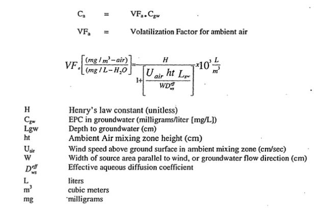
ASTM makes use of a simple, yet conservative, approach to the prediction of outdoor ambient air concentrations by the use of a “box model.” The box model is a simple mass-balance equation that uses the concept of a theoretically enclosed space or box over the area of interest. The model assumes the emission of compounds into a box, with the removal of the compounds based on wind speed. Airborne concentrations for the area can there be estimated and used to represent the onsite air concentrations.
23
For both the volatilization model and direct air measurements, the CTE concentrations were based upon the average modeled or measured value for each contaminant. RME concentrations were based on the calculated EPC for each modeled or measured contaminant air concentration. These calculated or measured air concentrations then formed the basis for the risk assessment.
Both the EPA Xxxxxxx and Xxxxxxxx and the ASTM model are based on a number of conservative and health-protective assumptions; accordingly, modeled indoor and outdoor air concentrations could be greater than actual concentrations that could occur at the Site, and risks and hazards estimated using these methods could err on the side of conservatism. However, in many cases at this site, the risk due to measured air concentrations is higher than the risk estimated from the groundwater volatilization model.
Input parameters used in the model were default values provided by EPA (2002) and ASTM (1995), with the exception of available site-specific parameters. Boring logs from representative monitoring xxxxx were evaluated and available site-specific data were extracted and entered into the model. Soil and groundwater characteristics data, used in the volatilization model, are provided in Table 12. Chemical and site-specific inputs used in the model are listed in Tables 13 and 14, respectively.
Intermediate model results (EPA J & E Intercalc Table) and the calculated indoor and outdoor air concentrations are provided in appendix E.
4.7.3.1 Differences between Draft Addendum and Revised Final HHRA
In the Draft Addendum HHRA dated December 16, 2003 a value for of 200 cm was used for the depth below grade to the bottom of the enclosed floor space (Lt). This has been changed to 15 cm, based upon comments received from one of the reviewers. In addition, the calculation of the area of the enclosed space below grade (Ab) and the crack-to-total area ratio (T\) were incorrectly linked to the floor-wall seam perimeter (Xcrack). Due to use of incorrect building crack data (which was too large), that was not linked to the theoretical building dimensions, the failure to properly link the actual building dimensions to the enclosed space below grade parameter resulted in an estimate of the total crack length being much greater than that present in the theoretical future building. This resulted in exaggerated estimates of indoor air concentration, and hence risk. This has been corrected and the values used in calculation of the air concentrations are shown in table 14 and appendix E. These changes were made based upon comments received on the Draft Addendum HHRA dated December 16, 2003 (see appendix F). Overall, correction of this error results in a lower risk estimate to the indoor worker.
24
| 4.7.4 | Exposure Parameters and Equations for Inhalation of Volatiles from Groundwater |
This HHRA addresses inhalation of volatile COPCs migrating from the underlying groundwater and/or soil. Exposure assumptions used in the intake calculations include inhalation rate and exposure time. These factors are shown in Tables 7 trough l0 and detailed below:
| • | Inhalation rate (IR): Inhalation rates for adults differ depending upon the receptor. For construction workers, a CTE IR of 1.5 cubic meters per hour (m3/hr; moderate activity level for outdoor work) and a RME IR of 2.5 m3/hr (heavy activity level for outdoor work) were used (USEPA, 1997a). IRs for indoor workers were 1.0 m3/hr (light activity level for indoor work) and 1.6 m3/h (moderate activity level for indoor work) for the CTE and RME exposure scenarios, respectively (USEPA, 1997a). Based on a 24-hour average, a CTE IR of 0.63 m3/hr (USEPA, 1997a) and a RME IR of 0.83 m3/hr (USEPA 2000a) were used for adult residents. For children 6 to 8 years of age, a CTE IR of 0.34 m3/hr (USEPA, 1997a) and an RME. IR of 0.42 m3/hr are recommended (USEPA, 2000). These are the highest recommended IRs for a child within the age range of l through 6 years. These values were used as conservative estimates of inhalation for children. |
| • | Exposure time (ET): An ET parameter was applied to the intake estimates to account’ for the amount of time during one day that a receptor can potentially inhale COPCs. For construction and indoor worker receptors, ETs were based upon a typical workday of 8 hours for the CTE scenario and an extended workday of 12 hours for the RME scenario (USEPA, 1997a). For the indoor worker it was assumed that 1 hour for the CTE scenario and 2 hours for the RME scenario would be spent outdoors. For the CTE scenario, an ET of 17.75 hours (16 hours indoors and 1.75 hours outdoors; USEPA, 1997a) was assumed for adult and child residents. The RME ET assumed for child and adult residents was 24 hours (22.25 hours indoors and 1.75.hours outdoors; USEPA, 1997a), which is very conservative because residents are typically not exposed all day to contaminants at their place of residence (indoors or outdoors). |
Chemical intake via inhalation of volatiles in indoor air was estimated according to the following equation:
| Intake | = | Cin × IR × EF × ET × ED | ||||
| BW × AT |
Chemical intake via inhalation of volatiles in the outdoor air, based upon flux measurements, was estimated according to the following equation:
| Intake |
= | Ca × IR × EF × ET × ED | ||||
| BW × AT | ||||||
| where: | ||||||
| Intake |
= | Intake, or dose, for each COPC (mg/kg-day) | ||||
| Cin |
= | EPC in indoor air (mg/m3 measured or modeled | ||||
| Ca |
= | EPC in ambient air (mg/m3 measured or modeled | ||||
| IR |
= | Inhalation rate (m3/hr) | ||||
| EF |
= | Exposure frequency (days per year) | ||||
| ET |
= | Exposure time (hours per day) | ||||
| ED |
= | Exposure duration (years) | ||||
| BW |
= | Body weight (kg) | ||||
| AT |
= | Averaging time (days). | ||||
25
5.0 TOXICITY ASSESSMENT
This section presents the toxicity assessment for the COPCs evaluated in the HHRA. The toxicity assessment includes identification of the types of potential toxicity associated with each COPC (i.e., noncancer and carcinogenic effects) and the chemical-specific dose-response relationships. The dose-response characterizes the relationship between the dose of a chemical and the probability of an adverse health effect in an exposed population.
5.1 Noncarcinogenic Toxicity Criteria
Dose-response criteria for assessing the potential for noncancer health effects from exposure to chemicals have been developed by USEPA on the principle (supported by scientific data) that noncancer health effects occur only after a threshold dose is reached. This threshold dose is usually estimated from the “No Observed Adverse Effect Level” (NOAEL) or the “Lowest Observed Adverse Effect Level” (LOAEL) determined from chronic (i.e., long-term) animal studies. The NOAEL is defined as the highest dose at which no adverse effects are observed, while the LOAEL is defined as the lowest dose at which adverse effects are observed.
Uncertainty factors, or safety factors, are applied to the NOAEL or LOAEL observed in animal studies or human epidemiological studies to establish reference doses (RfDs). A chronic RID, as defined by USEPA, is an estimate of continuous (i.e., chronic) exposure to the human population (including sensitive subgroups) that is likely to be without appreciable risk of deleterious effects during a lifetime (USEPA, 1989a).
In most cases, the RfD is calculated using non-toxic exposure levels in animals extrapolated to humans and reduced further using individual uncertainty factors ranging from 1 to 10. Uncertainty factors are used in an attempt to account for limitations in the quality or quantity of available dose-response data. For example, an uncertainty factor of 10 is applied to account for variation of the sensitivity of the human population. If the toxic endpoints are based upon animal studies, but applied to humans, an additional factor of 1 to 10 is applied. Ideally, the RfD is based upon the NOAEL. In those cases where only the LOAEL is available, another factor of 1 to 10 is applied. Similarly, if only sub-chronic data are available, then an uncertainty factor of 1 to 10 is applied. Finally, RfDs can be adjusted downward using a modifying factor of l to 10 to account for the quality of the toxicological studies or results. Thus, the uncertainty factors and the modifying factors provide an inherently more conservative RfD. If all uncertainty and modifying factors are applied at their maximum value of 10, then the endpoint doses observed in animal studies may be reduced by an overall factor of 10,000 for estimation of human exposures.
Rills developed by USEPA were used to evaluate noncarcinogenic health hazards in the HHRA. The current Rills were compiled from USEPA’s Integrated Risk Information System (IRIS; VSEPA, 200Ja). If values for a particular chemical were not in IRIS, the Health Effects Assessment Summary Tables (HEAST; USEPA, 1997c) were consulted, as suggested in USEPA’s risk assessment guidelines (USEPA, 1989a). If RfDs were not available in HEAST, RfDs were compiled from the National Center for Environmental Assessment (NCEA) as cited in USEPA (2000a).
26
The noncancer toxicity criteria for the COPCs are listed in Table 15 and discussed in Section 5.3 for each chemical. For purposes of this assessment and consistent with USEPA guidance (USEPA, 1998), oral Rills were used to represent dermal Rills (USEPA, 1989a). Where inhalation toxicity criteria were not available, oral toxicity criteria were used.
5.2 Carcinogenic Toxicity Criteria
Chemical carcinogens are generally divided into two classes, based upon the mechanism by which they cause cancer. These two classes are genotoxic agents (capable of causing DNA damage) and non- genotoxic (toxic through mechanisms not related to DNA damage). For genotoxic carcinogens, it is generally assumed that no threshold exists below which the agent cannot cause cancer. In other words, no matter how small the dose, there is some carcinogenic response, even if that response cannot be measured in animal experiments or in an exposed human population. In contrast to this, non-genotoxic carcinogens are likely to have a threshold dose, below which no adverse toxicological impact would be expected to occur. However, regulatory agencies, such as USEPA, have traditionally treated as chemical carcinogens as if there was no threshold for the carcinogenic effect. This is the most health conservative (i.e., most protective) approach to extrapolation of animal studies to humans.
The dose-response curve used by regulatory agencies is typically derived using the linearized multistage (LMS) model, which extrapolates the tumor response observe in animals exposed to high doses (commonly reaching the maximum tolerated exposure) of a chemical to a theoretical cancer risk for humans exposed to low doses. The LMS model is considered highly conservative because: (1) it does not allow for adjustments from metabolism or known DNA repair mechanisms that may prevent tumor formation at low doses, thus providing a threshold for the carcinogenic effect, and (2) it does not account for species differences that may result in chemical carcinogenicity by a mechanism only relevant to the specific laboratory animal.
The LMS model provides policymakers with an upper-bound risk estimate. Accordingly, USEPA acknowledges that the LMS mode] estimates are likely to greatly overestimate cancer risks (USEPA, 1986a):
It should be emphasized that the linearized multistage procedure leads to a plausible upper limit to risk that is consistent with some proposed mechanisms of carcinogenesis. Such an estimate, however, does not necessarily give a realistic prediction of the risk. The true value of the risk is unknown, and may be as low as zero. The range of risks defined by the upper limit given by the chosen model and the lower limit which may be as low as zero, should be explicitly stated. An established procedure does not yet exist for making “most likely” or “best” estimates of risk within the range of uncertainty defined by the upper and lower limit estimates.
In 1996, USEPA published proposed Guidelines for Carcinogen Risk Assessment (USEPA, 1996). The proposed guidelines are a revision of USEPA’s 1986 Guidelines for Carcinogen Risk Assessment, and when finalized, will replace the 1986 cancer guidelines. The proposed guidelines are intended to improve upon the 1986 guidelines by incorporating recent scientific advances in the understanding of carcinogenesis. Whereas the existing guidelines only allow for
27
a default approach (the LMS model) for extrapolating low-exposure risks to humans from high-exposure studies, the proposed guidelines allow for the application of biologically based models that incorporate an understanding of a chemical’s mechanism of action. Thus, where scientific studies of a chemical provide strong indication that a threshold is necessary for the initiation or promotion of carcinogenesis, the updated dose-response assessment can incorporate a threshold dose (VSEPA, 1996). Because the current methodology does not incorporate this mechanism of action (including possible threshold response), toxicity values derived using the 1986 cancer guidelines may result in greater overestimates of the potential risk of chemicals.
Cancer risks for exposure to carcinogens are defined in terms of probabilities. The probabilities identify the likelihood (based on the assumptions established in the model) of a carcinogenic response in a member of the exposed population who receives a given dose of a particular chemical (based on mathematical modeling of the dose-response data). The probabilities are expressed in terms of the slope factor (SF). The SF represents the probability of a carcinogenic response (per unit dose). The SF, multiplied by the predicted chemical dose, provides an estimate of the upper-bound theoretical excess cancer risk over the course of a 70-year lifetime.
SFs for this assessment were compiled from Cal/EPA’s Toxicity Criteria Database (Cal/EPA, 2001) and IRIS (USEPA, 2001a). For each COPC and exposure route, the higher SF from these two sources was used.
An important component of the toxicity assessment is an evaluation of the weight-of-evidence for human toxicity of each chemical. In assessing the carcinogenic potential of a chemical, USEPA’s Human Health Assessment Group (HHAG) classifies the chemical into one of the following groups, according to the weight-of-evidence from epidemiologic and animal studies (USEPA, 1997c):
| • | Group A - Human carcinogen (sufficient evidence of carcinogenicity in humans) |
| • | Group B - Probable human carcinogen (“B1” indicates limited evidence of carcinogenicity in humans; “B2” indicates sufficient evidence of carcinogenicity in animal, with inadequate or lack of evidence in humans) |
| • | Group C - Possible human carcinogen (limited evidence of carcinogenicity in animals and inadequate or lack of human data) |
| • | Group D - Not classifiable as to human carcinogenicity (inadequate or no evidence) |
| • | Group E - Evidence of non-carcinogenicity for humans (no evidence of carcinogenicity in adequate studies). |
Generally, quantitative carcinogenic risks are evaluated only for chemicals in Groups A and B and on a case-by-case basis for chemicals in Group C. The SFs, RfDs, and USEPA classifications for COPCs are presented in Table 15 and discussed in Section 5.3.
28
5.3 Toxicity Criteria for the COPCs
The following sections summarize the toxicity associated with the detected soil and groundwater contaminants, and COPCs evaluated in this HHRA and the derivation of cancer SFs and noncancer RfDs for each COPC. This information is summarized in Table 15.
Soil Only Contaminants
| • | Arsenic |
Arsenic is a known human carcinogen (Group A) based on increased lung cancer in human populations exposed via inhalation. In addition, liver, kidney, lung, bladder, and skin cancers have been observed from consumption of drinking water containing large amounts of inorganic arsenic. The oral noncancer toxicity value is based on hyperpigmentation, keratosis, and vascular complications. An inhalation RID is not available for arsenic.
| • | Cadmium |
Cadmium is a Group Bl, or probable, carcinogen based on human, occupational, and epiderniologic studies, as well as studies on laboratory rats and mice. An RID associated with food intake was applied to this HHRA based on human studies involving chronic exposures. There is no recommended inhalation RID for cadmium.
| • | Chromium (VI) |
Chromium (VI) is classified as Group A carcinogen via the inhalation route only, based on a relationship between occupational exposure and lung cancer. Carcinogenicity via the oral route has not been verified and thus, it is a Group D carcinogen by this pathway. The oral RID is based on the NOAEL in experimental animals. The inhalation RID was derived from occupational exposure via inhalation.
| • | Mercury |
Toxicity data for mercuric chloride were used to evaluate mercury in the HHRA. The RID is based on oral and subcutaneous administration to laboratory animals. The inhalation RID is based on the oral RID. Due to a lack of evidence in humans and limited data in animals, mercury is classified as a Group C, or possible, carcinogen; no SFs are recommended for mercury.
| • | Thallium |
Thallium carbonate was used as a surrogate compound for thallium. The oral RID was derived from observed increases in hormone levels in experimental animals. The oral RID was used for the inhalation pathway. Thallium is a Group D carcinogen due to a lack of carcinogenicity data in humans and animals.
| • | Carcinogenic PAHs |
The carcinogenic PAHs detected in onsite soil were benzo(a) anthracene, B(a)P, benzo(b) fluoranthene, benzo(k) fluoranthene, and chrysene. These compounds are classified as Group B2, or probable carcinogens. The SFs for these compounds are based on toxicity data for B(a)P (EPA, 1993). In multiple animal studies, B(a)P has been carcinogenic via several exposure routes. These compounds have not been demonstrated as causing noncancer health effects.
29
| • | Bis(2-ethylhexyl)phthalate |
Bis(2-ethylhexyl)phthalate is a probable carcinogen (Group B2). Increased liver tumors have been observed in laboratory animals exposed to the compound orally. Liver abnormalities were observed in animals exposed to the compound orally resulting in the oral RID value. The inhalation RID was based on the oral value in this assessment.
| • | Naphthalene |
Naphthalene is classified by USEPA as a possible carcinogen (Class C). However, recent studies by the National Toxicology Program (NTP) suggest that naphthalene is a carcinogen. The National Institute of Environmental Health Services of the National Institute of Health has indicated that naphthalene is a carcinogen via the inhalation route in laboratory animals (NTP, 2001). A SF has not yet been developed for naphthalene, however. The oral RID for naphthalene is based on a NOAEL in animal studies. The inhalation RID was derived from animal studies in which nasal effects were observed.
| • | Pentachlorophenol |
Pentachlorophenol is a Class B2 carcinogen, based on increases of several tumor types in laboratory animals and limited evidence in humans. The oral RID is based on liver and kidney effects in laboratory animals. The oral RID was used for the inhalation route in the HHRA.
| • | Polychlorinated Biphenyls |
PCBs are a Class B2; probable human carcinogen. This is based on a 1996 study that found liver tumors in female rats exposed to Aroclors 1260, 1254, 1242, and 1016, and in male rats exposed to 1260. These mixtures contain overlapping groups of congeners that, together, span the range of congeners most often found in environmental mixtures.
VOCs in Groundwater or Air
| • | Benzene |
Benzene is a known human carcinogen (Group A). This classification is based on epidemiologic studies that have demonstrated tumor responses by all exposure routes. The RfDs were compiled from NCEA (USEPA, 2000a) for which no supporting data were provided.
| • | Carbon Tetrachloride |
Carbon tetrachloride is classified as a probable human carcinogen (Group B2) based on hepatocellular carcinomas in mice, rats, and hamsters. The ND was derived from the NOAEL based upon liver lesions in rats.
| • | Chlorobenzene |
Chlorobenzene is not classifiable as to carcinogenicity in humans and hence is a Group D carcinogen. Based upon pathological changes in the liver, kidneys, gastrointestinal mucosa, and hematopoietic tissues of male and female beagle dogs, an RfD was derived from the NOAEL.
30
| • | Chloroethane |
No data on the carcinogenic potential of chloroethane was available. The RfC is based upon fetal toxicity in mice and is derived from the NOAEL.
| • | Chloroform |
Chloroform is a probable human carcinogen (Group B2) based on increased incidences of several tumor types in laboratory animals. The oral RfD was derived from the NOAEL; which is based on liver effects in dogs. In the HHRA, the oral RfD was used for the inhalation pathway in the absence of an inhalation RfD.
| • | 1,2-Dichlorobenzene |
1,2-Dichlorobenzene is classified as a Group D carcinogen by U.S. EPA. The RfD, derived from the NOAEL, is based upon liver lesions in mice.
| • | 1,3-Dichlorobenzene |
1,3-Dichlorobenzene is classified as a Group D carcinogen by U.S. EPA. The RfD is taken from NCEA. No supporting toxicological details were provided.
| • | 1,4-Dichlorobenzene |
1,4-Dichlorobenzene is classified as a Group B2 carcinogen by Cal/EPA. An RfC, based upon significant increases in liver weights for male rats, was derived from the NOAEL.
| • | 1,1-Dichloroethane |
1,1-DCA is a Group C, or possible, carcinogen. SFs were developed for 1,1-DCA based on an increased incidence of tumors in laboratory animals exposed to the compound. Oral and inhalation Rills were derived from NOAEL values based on kidney damage in animals.
| • | 1,2-Dichloroethane |
1,2-DCA is classified as a Group B2, or probable, carcinogen. Several tumor types were observed in laboratory animals exposed to the compound by gavage and topical applications. The RfDs for this compound were compiled from NCEA (USEPA, 2000a), which did not provide supporting data for the values.
| • | 1,1-Dichloroethene |
1,1-DCE is a Group C, or possible, carcinogen. Tumors were observed in one mouse strain exposed to the compound via inhalation. An inhalation slope factor is no longer available. 1,1-DCE is mutagenic and is known to alkylate and bind with DNA. The oral RfD is based on an observance of hepatic lesions in laboratory animals. There is no inhalation RfD for this compound; thus, the oral RfD was used for the inhalation pathway (for more discussion of the toxicity of 1,1-DCE, see Section 7.10.).
| • | Cis-1,2-Dichloroethene |
There are no data linking cis-1,2-DCE and tumor responses. Therefore, the compound is c1assified as a Group D carcinogen. The oral RfD was derived from observed blood abnormalities in laboratory animals. There is no recommended inhalation RfD; therefore, the oral RfD was used for this pathway in the assessment.
31
| • | Trans-1,2-Dichloroethene |
Trans-1,2-DCE does not have a carcinogenic c1assification, pending an evaluation by USEPA. An oral RID was derived from an animal study in which subjects were exposed orally to the compound. There is no inhalation RfD; therefore, the oral RfD was used in the HHRA for this pathway.
| • | 1,2-Dichloropropane |
1,2-Dichloropropane is not classified a carcinogen by USEPA or Cal/EPA. The RfC is based upon nasal lesions in mice, rats, and rabbits. The RfC was derived from the LOAEL.
| • | Cis- and Trans-1,3-Dichloropropene |
1,3-Dichloropropene (a mixture of cis- and trans- isomers) is classified a probable human carcinogen based upon observations of tumors in F344 rats (forestomach, adrenal and thyroid tumors, and liver nodules) and B6C3Fl mice (forestomach, urinary bladder, and lung tumors), positive mutagenic activity, and structural similarity to known oncogens that produce similar types of tumors in rodents. The RfD was derived from the NOAEL and based upon) increased kidney weights in rats. The RfC was based upon observed changes in respiratory and olfactory epithelium in both mice and rats. The RfC was derived from the NOAEL.
| • | 1,4-Dioxane |
1A-Dioxane is classified a probable human carcinogen (Group B2). The classification is based on: (1) induction of nasal cavity and liver carcinomas in multiple strains of rats, (2) liver carcinomas in mice, (3) gallbladder carcinomas in guinea pigs. Oral and inhalation RfDs are not available for non-carcinogenic effects.
| • | Ethyl benzene |
Ethyl benzene is currently classified as Group D by USEPA. The RfD is based on histopatholog c changes in the liver and kidneys of female rats and derived from the NOAEL.
| • | Freon 113 (1,1,2-Trichloro-1,2,2-triDuoroethane) |
No information on the carcinogenicity of Freon 113 was available. The RfD was derived from the NOAEL, and based upon slight impairment of psychomotor performance in male human volunteers. No supporting toxicological data was available on the derivation of the RfC.
| • | Methylene Chloride |
Methylene chloride is a Group B2, or probable carcinogen. Increased incidences in several tumor types have been observed in animals exposed to the compound. The oral and inhalation RfDs are based on observed liver toxicity in laboratory studies.
| • | 1,1,2,2-Tetrachloroethane |
1,1,2,2-Tetrachloroethane is a group C carcinogen (possible human carcinogen) based on increased incidence of hepatocellular carcinomas in mice. No supporting toxicological data was available for the RfD.
32
| • | Tetrachloroethene (PCE) |
USEPA has not classified the carcinogenic potential of PCE. Cal/EPA (2001) has developed SFs for PCE based on liver. carcinomas in laboratory animals. An oral RFD for this compound was derived experimentally based on observed liver toxicity in animals. The inhalation RFD was compiled from NCEA (USEPA, 2000a) and no supporting data were provided.
| • | Toluene |
Toluene is a Group D (not classified) carcinogen. The RFD is based upon histopathologic changes in the liver and kidneys, as well as increased liver and kidney weights, in rats. This RFD was derived from the NOAEL.
| • | 1,1,1-Trichloroethane |
1,1,1-Trichloroethane does not have a carcinogenic classification (Group D). The oral and inhalation reference doses were compiled from NCEA (USEPA, 2000a) and no supporting data were provided.
| • | 1,1,2-Trichloroethane |
1,1,2-Trichloroethane is classified group C; possible human carcinogen. This is based on hepatocellular carcinomas and pheochromocytoma in one strain of mice forms the basis for this classification. Carcinogenicity was not shown in rats. 1,1,2-Trichloroethane is structurally related to 1,2-dichloroethane, a probable human carcinogen. The RfD was derived from the NOAEL and based upon adverse liver effects in mice.
| • | Trichloroethene (TCE) |
USEPA recently reviewed the carcinogenic potential of TCE (USEPA, 200Jd). The upper bound slope factor of0.4 (mg/kg-day) 1 calculated in this document was used for this HHRA. Cal/EPA (2001) has developed SFs for TCE based on liver and lung carcinomas in laboratory animals. The RfDs were compiled from NCEA (USEPA, 2002a) and no supporting data were provided. Based upon the revised TCE risk assessment (USEPA, 2001d) and the USEPA Region IX PRG tables (USEPA, 2002a), an inhalation reference dose of 0.01 mg/kg-day was used to estimate non-carcinogenic health effects. Epidemiologic studies have associated TCE exposure with excess risks of kidney cancer, liver cancer, lympho-hematopoietic cancer, cervical cancer, and prostate cancer. Observed non-catcinogenic effects include neurotoxicity, immunotoxicity, developmental toxicity, liver and kidney toxicity, and endocrine effects (see also Section 7.11).
| • | Vinyl Chloride |
VC is classified as a known human carcinogen (Group A). The c1assification is based on (1) epidemiologic evidence for inhalation exposure in occupational scenarios, (2) carcinogenicity in laboratory animals, (3) mutagenicity and DNA adduct formation in in-vitro tests, and (4) the rapid absorption of VC following exposure. The oral and inhalation RfDs are based on observed liver cell changes in laboratory animals.
| • | Xylenes |
Xylene (dimethylbenzene) exists in three isomeric forms; o-Xylene (ortho or 1,2-dimethlybenzene), m-Xylene (meta or 1,3-dimethylbenzene), and p-Xylene (para or 1,4-dimethylbenzene). Due to their close physical and toxicological properties, all three isomers are
33
grouped together as one chemical “Xylenes” by USEPA and classified as non-carcinogenic (class D). CNS toxicity and respiratory effects have been observed in rats at relatively high doses. Xylenes have been observed to be fetotxic and teratogenic at high doses in mice. The inhalation RID was based on the oral RID.
34
6.0 RISK CHARACTERIZATION
In risk characterization, the information, results, and conclusions from the data evaluation, exposure assessment, and toxicity assessment are integrated. Numerical risk estimates calculated for each COPC and exposure route and pathway are combined to estimate total theoretical noncancer hazards and, for carcinogens, total lifetime excess cancer risks. The critical uncertainties affecting risk calculations are also addressed.
6.1 Noncarcinogenic Hazard
Noncarcinogenic effects for each exposure route and pathway, and for each chemical are evaluated by comparing an average dose to a RID for the same time period, generally one day. The ratio of the average daily dose to RID is called a hazard quotient (HQ), which is calculated as follows:
| HQ |
= | ADD | ||
| RfD | ||||
| Where: | ||||
| HQ |
= | Theoretical noncancer hazard quotient for a specific chemical and exposure pathway | ||
| ADD |
= | Average Daily Dose (mg/kg-day) for chemical and exposure pathway | ||
| RfD |
= | Reference Dose (mg/kg-day) for chemical and exposure pathway. | ||
The HQ assumes that there is a dose below which adverse health effects are unlikely (USEPA, 1989a). If the average daily dose is below the threshold RID (i.e., the ratio is less than 1), it is unlikely that noncarcinogenic effects would occur. The HQ is specific to chemicals and exposure pathway combination. Therefore, to assess the overall potential for noncarcinogenic effects from a particular exposure scenario, HQs for the relevant individual exposure pathways (e.g., ingestion, dermal contact, and inhalation) and individual chemicals are summed to obtain the hazard index (HI) for the populations evaluated.
In general, it is USEPA’s position that a theortical HI value at or below indicates that there is unlikely to be an increased health risk, even for sensitive populations (USEPA, 1989a). At the same time, a HI greater than 1 does not necessarily indicate that adverse effects will occur, because the RID used in the calculation contains a substantial measure of conservatism. As previously discussed, the RID is conservative because it is typically derived by applying multiple safety factors to a level at which no adverse effects have been observed or to the lowest level at which effects have been observed in the most sensitive animal species that have been tested.
A significant limitation of the HIs is related to the assumption of additivity. Additivity is most properly applied to compounds that induce the same effect by the same mechanism of action. Summing HIs for a number of compounds that are not expected to induce the same type of
35
effects or that do not act by the same mechanism is likely to further overestimate the potential for effects. However, for this HHRA, all of the COPCs are assumed to have similar toxicological endpoints, because they are all solvents with similar mechanisms of action. Thus, summing of HIs is likely appropriate and is not expected to result in significant overestimation of risk.
6.2 Cancer Risks
The theoretical lifetime excess cancer risks associated with the lifetime average daily doses are calculated as the product of the lifetime average daily dose (XXXX) and the SF for each chemical and exposure pathway as shown below:
| Risk |
= | SF × XXXX | ||
| Where: | ||||
| Risk |
= | Theoretical lifetime excess cancer risk for chemical and exposure pathway | ||
| SF |
= | Slope Factor for chemical and exposure pathway | ||
| XXXX |
= | Lifetime Average Daily Dose for chemical and exposure pathway. | ||
The quantitative risk estimate for suspected carcinogens is expressed as the lifetime theoretical excess (or additional) risk of contracting cancer above the actual incidence of cancer in the U.S. population. The likelihood of actually developing cancer is l-in-2 for a male and 1-in-3 for a female (American Cancer Society, 1999). The risk estimate is chemical- and exposure pathway-specific. Therefore, the total upper-bound theoretical excess cancer risk is calculated by combining the risks across exposure pathways and chemicals as follows:
Total lifetime theoretical excess risk = Sum of risks by chemical and pathway.
USEPA has provided guidance on the role of risk assessment in federal Superfund remedy selection (USEPA, 199lb). USEPA considers a target lifetime theoretical excess risk range of lx l0-6 to 1x10⁴ (between one-in-one-million and one-in-ten thousand) to be “safe and protective of public health.”
According to USEPA, where the total lifetime theoretical excess cancer risk to an individual (based on an RME scenario for both current and future land use) is Xxxx than 1x10⁴ and the theoretical noncarcinogenic HI is less than 1, remedial action is generally not warranted unless there are other adverse environmental impacts or an applicable or relevant and appropriate requirement (XXXX) is exceeded. Even risks slightly greater than l x 10-4 may be considered to be acceptable (i.e., protective) if justified based on site-specific conditions, including uncertainties about the nature and extent of contaminants and associated risks. Alternatively, on a case-by-case basis, action may be recommended for sites within the 1x 10⁻⁴ to lx 10-6 risk range. Where remedial action is warranted, guidance for remedy selection is provided in the USEPA directive entitled Land Use in the CERCI.A Remedy Selection Process (USEPA, 1995). The directive notes that it is not USEPA’s intent that acceptable risk standards be based solely on categories of land use (e.g., with residential cleanups at a lx l0-6 level or industrial cleanups at a
36
lx l0-4 1evel). The Regional Water Quality Control Board, San Francisco Bay Region has accepted 1 x l0-5 cleanup ‘levels on a site-specific basis. Therefore, the risk range provides the risk manager with the necessary flexibility to address technical and cost limitations, and the performance and risk uncertainties inherent in all site remediation efforts.
6.3 Risk Characterization Results
In this section, the quantitative evaluations of theoretical noncancer hazards and lifetime theoretical excess cancer risks are presented for each app1icable receptor for air concentrations estimated using the ground water volatilization mode] and direct air measurements evaluated. Quantitative risks and hazards were estimated under RME and CTE conditions for the data sets described in Section 3.0 (i.e., using groundwater and air). These estimates are summarized in Tables 16 through 25, and Plates 4 through 22. Quantitative risks were compared to the USEPA risk management range of Ix 10-6 to 1x 10⁻⁴. Lifetime excess carcinogenic risks within the risk management range may be managed through construction techniques (indoor air) to reduce risks to an acceptable level and the use of appropriate personal protective equipment (PPE, construction). For the NRP, the acceptable lifetime excess cancer risk level is lx l0-6. Where risk management techniques are not available to achieve acceptable risk, NASA will implement land use controls. Noncancer hazards were compared to a HI of 1. As discussed in Section 1.0, analytical data for residual soil contamination were not available. Therefore, applicable clean-up target contamination levels (TCLs) for soil were compiled and are discussed in Section 6.4.
As discussed previously, EPCs for individual contaminants were calculated for each well (groundwater) and each building (air). Within each well or building, risks and hazards were calculated based upon the EPC of the COPCs in groundwater and measured air values using the appropriate models. Tables 16 through 25 contain the detailed risks and HIs for individual chemicals for each well or building.
When calculating risks and HIs, special consideration must be given to vinyl chloride (VC), benzene, and 1,4-dioxane. Although VC was detected in some of the groundwater samples, it was not detected in any of the flux or air samples. When calculating risk using groundwater data, the groundwater volatilization model used to estimate air concentrations would tend to overestimate risks because of the presence of VC. In particular, the GW-to-Indoor air model predicted indoor concentrations for VC at levels above the average indoor air measurement detection levels. Since the air measurement technique employed should have detected VC if present at the predicted model levels, it appears that the model, as used, over predicts indoor air VC concentrations. The calculated risk, at the average detection limit of the indoor air sampling, corresponds to a risk less than lx l0-6. Therefore, where VC was present in the groundwater, risks were estimated by subtracting out the VC risk. These VC corrected risks and HIs formed the basis for the data used to generate the iso-risk and HI contours in Plates 4 through 22.
Contaminant levels measured in air may include multiple sources for any given chemical. In particular, benzene risks based upon the air data can be greater than that expected from the groundwater data. Benzene is ubiquitous in the urban atmosphere, primarily due to vehicle exhausts. For many of the estimated risks and HIs that were based on air measurements, benzene was the single largest contributor to the total risk, even where it was not detected in the
37
underlying groundwater plume. Therefore, it was concluded that the presence of benzene in the air data could be, for certain buildings, primarily a result of background concentrations, and not because of significant soil vapor migration from the groundwater plume. Consequently, concentrations due to the presence of background benzene in the air data were subtracted from the measured benzene concentrations. In addition to benzene, background corrections (Table 6) were also applied for toluene, methylene chloride, 1,1,1 -trichloroethane, tetrachloroethene (PCE), and trichloroethene (TCE). As discussed previously, 1999 data for the BAAQMD Mountain View monitoring station was used to make this adjustment. Improvements in automobile emissions controls and the use of reformulated gasoline since 1999 should result in decreased background ambient air concentrations for some of these chemicals (e.g. benzene). However, only BAAQMD data for 1998 and 1999 were available for the Mountain View location. For benzene, toluene, methylene chloride, and trichloroethene the 1998 mean values were greater then the 1999 mean values; a trend towards improving air quality. However, for perchloroethlyene and trichloroethylene the 1999 mean values were greater than the 1998 mean values. Indoor air measurements were taken in 1999 and 2000, therefore these background concentnltions are likely representative of the actual background concentrations in the air during the site sampling.
The third chemical requiring additional consideration, 1,4-dioxane, was detected in many flux and air samples, but was not part of the suite of chemicals historically analyzed in the groundwater. Recent sampling has detected 1,4-dioxane only at low levels and only in some of the samples from the Al aquifer underlying the site. The presence of 1,4-dioxane in the indoor air could result from off gassing of building materials, from other solvent-containing products used in the buildings, or be present as a background contaminant in urban air. However, although risks calculated from air data may be overestimated under these circumstances (i.e., airborne 1,4-dioxane concentrations are higher than would be expected from the groundwater data), no correction is incorporated because background air data from the BAAQMD were not available for 1,4-dioxane.
The overall carcinogenic risks and noncancer HIs for the NRP are summarized in Section 6.3.1 for each receptor. Section 6.3.2 presents the calculations of risks and HIs from the groundwater volatilization model. Section 6.3.3 presents the risks and HIs estimated using the measured air concentration data.
6.3.1 Risk Characterization Summary
In general, the highest estimated lifetime excess cancer risks were located primarily in parcels 1, parts of 2 and 5, 7, 13, 14, 15, 17, and 18 (see Plates 4 through 22). The estimated lifetime excess cancer risks and HIs for all receptors were highest in Parcel.15 or the space east of 15 (xxxxx W9-l8, W9-35, WIC-11, and WIC-12, see Tables 16 through 20). For construction workers and adult residents (10 year RME, 5 year CTE), RME and CTE risks estimated from the groundwater volatilization model were within the risk management range. For the indoor worker, child resident (10 year RME, 5 year CTE), and default 30-year residential receptor, the lifetime excess cancer risks estimated from the groundwater volatilization model were above the risk management range for at least one wen in Parcel 15 (W9-18, W9-35, WIC-11, or WIC-12). Estimated lifetime excess cancer risk based on the measured air concentrations were above the
38
risk management range for buildings within or adjacent to Parcel 15, for all receptors except the construction worker. In addition, lifetime excess cancer risks estimated from groundwater volatilization modeling for the eastern portions of Parcels 12 and 12a, the northern portion of Parcel 5, and parts of Parcels 1, 2, and 7 were within the risk management range for all receptors.
For some of the buildings (e.g. 21, 22, 476, 148, and 156) on the western boundary of the plume, the estimated lifetime excess cancer risks, based upon the measured air data for some exposure scenarios, were many orders of magnitude greater than that which would have been predicted using the groundwater volatilization model and measured groundwater concentrations for xxxxx in the vicinity of the building. This discrepancy may be due to: 1) contaminants present in the background air but which could not be corrected for due to a lack of BAAQMD background data; 2) differences between actual building parameters (such as ventilation rate or building floor wall perimeter crack length and modeled building parameters); 3) contaminant sources other than groundwater which have not been identified nor for which data were available to correct the air measurement data; 4) inaccuracy in the groundwater volatilization model.
The results of the HHRA for each receptor are summarized as follows:
| • | Maximum RME lifetime excess cancer risk for construction workers was within the USEPA risk management range (lx l0-6 to lx l0-4) based upon the groundwater volatilization modeling and direct air measurement results. The maximum estimated RME and CTE HIs for the construction worker, based upon the groundwater volatilization modeling and direct air measurements were greater than 1. This is primarily due to direct exposure to the contaminated groundwater. |
| • | RME lifetime excess cancer risks for indoor workers, estimated from the groundwater volatilization model, were within or below the risk management range, except for one well in parcel 15 (W9-35). RME lifetime excess cancer risk estimated from the air measurements was above the risk management range (2.3E-4) for four buildings (Building 156, 566, 6 and Hangar 1), but within the risk management range for the remaining buildings. However, lifetime estimated excess cancer risks estimated from xxxxx near Buildings 6, 156 and 566 were all in the lower end of the risk management range. This high estimated lifetime excess cancer risk for Buildings 156 and 566 may due to sources other than contaminated groundwater (note that Building 156 is very close to highway 101) or there may be high contaminant levels in the soil or groundwater close to the building, but which are not detected in the current monitoring xxxxx. If the results for Building 156 are considered anomalous, then Hangar 1 has the highest estimated lifetime excess cancer risk. This building is adjacent to Well W9-35, which has the highest estimated lifetime excess cancer risk based upon the groundwater volatilization modeling. This suggests that the results for Hangar 1 are associated with contaminants in the groundwater. Maximum RME HIs for indoor workers estimated from both the groundwater volatilization model and direct air measurements were less than or equal to I and the CTE HIs were less than 1. |
| • | Maximum RME and CTE lifetime excess cancer risks for adult residents (10 year and 5 year exposure duration, respectively), estimated from the groundwater volatilization model, were within or below the risk management range. RME lifetime excess cancer risks estimated from the air measurements were above the risk management range for Building 156, 6, and Hangar 1 |
39
| but within the risk management range for the remaining buildings. The high estimated lifetime excess cancer risk for Building 156 may due to sources other than contaminated groundwater, because the risks estimated from xxxxx in the vicinity of this building were all below or at the low end of the risk management range. If the results for Building 156 are considered anomalous, then Hangar 1 has the highest estimated lifetime excess cancer risk. CTE lifetime excess cancer risks estimated from the air measurements were below the risk management range for Building 111, and within the risk management range for the remaining buildings. Maximum RME HIs for adult residents (10 year exposure duration) estimated from the groundwater volatilization model were less than 1. Maximum RME HIs based upon direct air measurements were greater than 1 (Building 6), but the CTE (5 year exposure duration) HIs for all buildings were less than 1. |
| • | RME lifetime excess cancer risks for child residents (I 0 year exposure duration), estimated from the groundwater volatilization model, were within or below the risk management range except for two xxxxx (W9-35 and W9-2) in parcels 15 and 13. CTE lifetime excess cancer risks for child residents (5 year exposure duration), estimated from the groundwater volatilization model, were within or below the risk management range for all parcels. RME lifetime excess cancer risk estimated from the air measurements was above the risk management range for Buildings 148, 2, 21, 566, 156, 6, and Hangar 1. As discussed previously, the results for Buildings 566, 21 and 156 may be due to sources other than groundwater contamination. However, the results for the remaining buildings appear to be associated with groundwater contaminants, based upon comparison to lifetime excess cancer risk estimated from xxxxx near these buildings using the groundwater volatilization model. Maximum RME lifetime excess cancer risk estimated from contaminant concentrations in xxxxx near Buildings 566, 21 and 156 were between one to two orders of magnitude lower than risks estimated from the indoor air measurements. Maximum RME (10 year exposure duration) and CTE (5 year exposure duration) HIs for child residents estimated from the groundwater volatilization model were less than 1.Maximum RME (10 year exposure duration) HIs for child residents estimated from direct air measurements were greater than 1 for Building 6, but less than or equal to 1 for the remaining buildings. Maximum CTE (5 year exposure duration) child resident HIs were less than or equal to 1 for all buildings. |
| • | Maximum RME lifetime excess cancer risk for 30-year residents, estimated from the groundwater volatilization model, was above the risk management range. RME lifetime excess cancer risk estimated from the air measurements was also above the risk management range for Buildings 148, 156, 2, 21, 476, 566, 6, and Hangar 1. As discussed previously, the results for Buildings 566, 156, 21 and 476 may be due to sources other than groundwater contamination. The maximum excess lifetime cancer risks estimated from contaminant concentrations in xxxxx in the vicinity of these buildings were all lower by at least one order of magnitude. However, the results for the other buildings do appear to be associated with groundwater contaminants, based upon comparison to lifetime excess cancer risk estimated from xxxxx near these buildings using the groundwater volatilization model. Maximum adult and child His, estimated from both the groundwater volatilization model and direct air measurements, were greater than 1. |
40
6.3.1.1 Differences between Draft Addendum and Revised HHRA
As discussed in section 4.7.3.1, the groundwater to air volatilization model was revised based upon comments received on the Draft Addendum HHRA dated December 16, 2003. Overall, these changes result in lower risk estimates for most xxxxx.
6.3.2 Risk Estimated from Groundwater Volatilization Model
The individual estimated lifetime excess carcinogenic risks and HIs for each well and receptor are presented in Tables 16 through 20 and Plates 4, 5, 8, 9, 12, 13, l6, l7, and 20. As shown in the tables, risks and HIs were calculated with vinyl chloride (VC) present, as wen as VC subtracted from the total risk and HI. As discussed in Section 6.3, VC was detected in the groundwater but not in the air or soil flux samples. Therefore, although the presence or absence of VC in the various media is noted for each of the xxxxx, the most applicable total risk estimates do not take into account the presence of VC in the groundwater. All of the iso-risk plots presented in the plates are exclusive of VC. The risks discussed below for each receptor are exclusive of VC. Other chemicals, such as carbon tetrachloride, were not detected in air, but were also not on the flux analytes list. As discussed in section 3.3, under these circumstances, in order to err on the conservative side, these chemicals were kept as COPCs.
Since the groundwater volatilization model is based upon contaminant groundwater concentrations, no correction for contaminant concentrations in background air is required. Consequently, Benzene and the other contaminants measured by BAAQMD iri the background air were included in the risks that were estimated using the groundwater data without correction.
Construction Workers
Table 16 and Plates 4, 5, 6, and 7.
Lifetime excess RME and CTE cancer risk for all of the parcels were within or below the risk management range. The space east of Parcel 15 (well W9-35) had the highest (3.lx I0-5 maximum lifetime excess cancer risk. RME lifetime excess cancer risks were within the risk management range for Parcels l , 2, 3, 4, 5, 6, 7,12, 12a, 13, 14, 15 and the space east of 15, 17, and 18. CTE lifetime excess cancer risks were within the risk management range for Parcels 5, 13, 15 and the space east of I5, and 17. RME HIs were above l for parcels 2, 5, 13, 14 15 and the open space east of 15, and 17. CTE HIs were above l for Parcels 13, 15 and the open space east of 15.
Indoor Workers
Table 17 and Plates 8, 9, l 0, and 11.
Lifetime excess RME and CTE cancer risk for all of the parcels were within or below the risk management range. The space east of Parcel 15 (well W9-35) had the highest (l.3x 10-4) maximum lifetime excess cancer risk. This was the only well above the risk management range, however the results for this one well does not significantly impact the risk estimate (within the risk management range) for the entire parcel. RME lifetime excess cancer risks were within the risk management range for Parcels 1, 2, 4, 5, 7, the eastern portions of 12 and 12A, 13, 14, 15
41
and the space east of 15, 17, and 18. Parcels 13, 15 and the space east of 15, and 17 had CTE lifetime excess cancer risks within the risk management range. The remaining parcels all had CTE lifetime excess cancer risks below the risk management range. All parcels had an RME and CTE HIs less than 1.
Adult (10-year RME, 5-year CTE)
Table 18 and Plates 12, 13, 14, and 15.
Lifetime excess RME and CTE cancer risk for all of the parcels were within or below the risk management range. The space east of Parcel 15 (well W9-35) had the highest (8.3x 10⁻⁵) maximum lifetime excess cancer risk. RME lifetime excess cancer risks were within the risk management range for Parcels 1, 2, 4, 5, 7, the NE xxxxx of 12A, 13, 14, 15 and the space east of 15, 17, and 18. CTE lifetime excess cancer risks for Parcels l, 2, 3, 5, 13, 14, 15 and the space east of 15, 17, and 18 were within the risk management range. RME and CTE HIs for all parcels were less than 1.
Child (10-year RME, 5-year CTE)
Table 19 and Plates 16, 17, 18, and 19.
Lifetime excess RME cancer risk for Parcels 13 and 15 and the space east of Parcel 15 was above the risk management range. The space east of Parcel 15 lifetime excess cancer risk (2xl0-4 well W9-35). RME lifetime excess cancer risks were within the risk management range for Parcels 1, 2, 3, 4, 5, 6, 7, 12A, the eastern edge of 12, 14, 17, and 18. CTE lifetime excess cancer risks for Parcels 1, 2, 3, 4, 5, 7, the eastern edge of 12 and 12A, 13, 14, 15 and the space east of 15, 17, and 18 were within the risk management range. RME and CTE HIs were less than I for all parcels.
Default 30-year Resident
Table 20 and Plates 20; 21, and 22.
The estimated maximum lifetime excess cancer risk for the default 30-year residential receptor for Parcels 13, 14, 15 and the space east of Parcel 15, and NE xxxxx of 17 were above the risk management range. Well W9-35, in Parcel 15, had the highest estimated lifetime excess cancer risk (3.2x 10⁻⁴). RME lifetime excess cancer risks were within the risk management range for all other parcels. For Parcels 12 and l2A, only the very eastern portions were within the risk management range. The remainders of these two parcels were below the risk management range. Both adult and child RME HIs (10 year exposure) were less than 1 for all parcels.
| 6.3.3 | Risk Estimated from Air Measurements |
Because benzene is present in ambient air, background benzene concentration, based upon the BAAQMD monitoring station in Mountain View was subtracted from the total measured benzene concentration (Table 6). In addition to benzene, background corrections (Table 6) were also applied for toluene, methylene chloride, 1,1,1-trichloroethane, tetrachloroethene (PCE), and trichloroethene (TCE). Since VC was not detected in any air sample, the risks presented for each building do not include a contribution from VC. Risks associated with these background concentrations, for each receptor, are provided in Table 26.
42
For the construction worker receptor risks were the result of exposure to groundwater (dermal) as well as air. Risks for all other receptors are based only on the direct air measurements. In order to account for the construction worker dermal exposure, the groundwater concentrations are based upon the maximum for each chemical for groupings of xxxxx in closest proximity (within approximately 500’ radius) to the building in question. (For GW vapor transport into buildings, each well was considered individually.) For the CTE exposure scenario, the maximum of the average of any chemical/well was used. For the RME exposure scenario, the maximum EPC for any well/chemical was used.
Construction Workers
Table 21 and Plates 4, 5, 6, and 7.
Lifetime excess RME and CTE cancer risk for all of the buildings were within the risk management range except Building 111, which was below the risk management range. CTE lifetime excess cancer risks were within the risk management range for Buildings 148, 15, 2, 476, 555, 566, 583C, 6, and Hangar 1. RME HIs were equal to or greater than 1 for Buildings 148, 15, 2, 476, 555, 566, 583C, 6, and Hangar 1. Hangar 1 had the highest RME HI (9). CTE HIs were greater than l for Buildings 15, 6, and Hangar 1. For most receptors, the Building 6 HI is greater than that calculated for Hangar 1. For the construction worker, the Hangar l HI is equal to the HI for Building 6 due to the assumption of direct dermal exposure to groundwater. As explained above, groups of groundwater xxxxx in closest proximity to the building were used to evaluate the dermal exposure. Different wens were considered for Building 6 and Hangar 1 based upon the 500’ radius from each well. The result is that for many chemicals, the groundwater concentration used to evaluate the dermal exposure was the same for these two buildings. However, for one well associated with Hangar 1, WU4-l0, 1,4-dioxane was detected. None of the xxxxx associated with Building 6 had 1,4-dioxane. Due to the 1,4-dioxane RID, the HI for the Hangar l construction worker equals the HI for the Building 6 construction worker.
Indoor Workers
Table 22 and Plates 8, 9, 10, and 11.
Lifetime excess RME cancer risks for all of the buildings were within the risk management range, except Buildings 156 (2.3x l0-4), 566 (1.1x10⁻⁴), 6 (l.5x 10-4 and Hangar l (1.7x 10⁻⁴) which were above the risk management range. However, Plate 8 reveals that Building 566 and 156 are located on the very edge of the known groundwater plume. Lifetime excess cancer risks estimated from the groundwater volatilization model for xxxxx near this building were all significantly lower by about two orders of magnitude. In addition, Building 156 is located relatively dose to State Highway 101. These factors seem to indicate that the measured concentrations for this building might be due to sources other than contaminated groundwater. All of the buildings had CTE lifetime excess Cancer risks within or below the risk management range. RME and CTE HIs for all buildings were Jess than or equal to l.
43
Adult (10-year RME, 5-year CTE)
Table 23 and Plates 12, 13, 14, and 15.
Lifetime excess RME cancer risks for Buildings 156, 6, and Hangar 1 were above the risk management range, however all of the remaining buildings were within the risk management range. Xxxxx closest to Building 156 had estimated lifetime excess cancer risks based upon contaminant concentrations in the groundwater at least two orders of magnitude lower than the risk estimated for Building 156 from the measured indoor air concentrations. As discussed previously, the indoor air concentration of contaminants in Building 156 may be due to sources other than the underlying groundwater. All of the buildings had CTE lifetime excess cancer risks within the risk management range, except Building 111, which was below the risk management range. Only Building 6 had an RME HI greater than 1. CTE HIs for all buildings were less than 1.
Child (10-year RME, 5-year CTE)
Table 24 and Plates 16, 17, 18, and 19.
Lifetime excess RME cancer risks for Buildings 148, 156, 2, 21, 566, 6, and Hangar l were above the risk management range. Lifetime excess RME cancer risks for the remaining buildings were all within the risk management range. As previously discussed, the results for Building 21, 566, and 156 may be due to sources other than contaminated groundwater. Lifetime excess cancer risk based upon contaminant concentrations in xxxxx closest to these buildings were all at least one order of magnitude lower than the estimate based upon the measured indoor air concentrations. All of the buildings had CTE lifetime excess cancer risks within the risk management range. Only Building 6 and Hanger l had RME HIs greater than or equal to 1. CTE HIs for all buildings were less than or equal to 1.
Default 30-year Resident
Table 25 and Plates 20, 21, and 22.
The estimated maximum lifetime excess cancer risk for the default 30-year residential receptor for Buildings 148, 156, 2, 21, 576, 566, 6, and Hangar 1 were all above the risk management range. RME lifetime excess cancer risks were within the risk management range for all the other buildings. As per the previous discussion, the results for Buildings 21, 156, 476, and 566 may be due to sources other than contaminated groundwater, based upon risk estimates for xxxxx near these buildings. Only Building 6 had an Adult or Child HI greater than I.
6.4 Soil Target Cleanup Levels
Soil TCLs were obtained from the U.S. EPA Region IX PRGs (USEPA, 2000a); Cal/EPA RBSLs, and the MEW ROD (USEPA, 1989b). These data are summarized in Table 26. For an individual chemical, the lowest soil TCL from the three data sources will be used to assess future measured soil concentrations. Use of the values selected will result in conservative soil cleanup levels to support future removal action decisions. If TCLs are less than background metals, background concentrations will be used as the TCL.
44
7.0 UNCERTAINTY EVALUATION
Uncertainty is inherent in many aspects of the risk assessment process. Direct measurements are not available for many of the criteria upon which the risk estimates are dependent (e.g., human exposure parameters, and the toxicity criteria used to assess the potential for adverse effects at. very low dose levels). Therefore, conservative assumptions and methodologies were employed to reduce the possibility of underestimating risk. The following sections provide more detailed information on some, but not all, of the most significant areas of uncertainty.
7.1 Toxicity Criteria and Factors
Many toxicity factors used in human health risk assessments are based on animal data and, therefore, potentially overestimate risk. In most cases, the noncancer RID is calculated using animal data for nontoxic exposures that are extrapolated to humans and the RID is further reduced using uncertainty and modifying factors (Section 5.1). These factors provide an inherently conservative RID. For chemicals that are classified as probable human carcinogens (i.e., lacking evidence of carcinogenicity in humans), the USEPA method for developing cancer SFs extrapolates data from high-dose animal experiments to low-dose human exposures, and thus is associated with a high potential for overestimating risk. Actual SFs could be lower but are unlikely to be higher. The linearized multistage model used to perform this extrapolation is considered conservative (Section 5.2).
For chronic and lifetime exposures, the simplifying assumption that all chemical concentrations will remain constant is employed. This assumption is likely to result in an overestimate of chronic or lifetime exposure for chemicals that biodegrade over time or are undergoing remediation.
When humans are exposed to more than one chemical in a medium, it is normally assumed that the adverse effects of the different chemicals are additive (USEPA, 1989a). However, in some cases synergistic or antagonistic interactions may occur. Although there are no data to suggest that synergistic or antagonistic interactions occur between the COPCs at the Site, this possibility is nevertheless a source of uncertainty in the HHRA.
7.2 Exposure Pathways and Parameters
A large part of the risk assessment is the estimation of lifetime theoretical excess cancer risks and theoretical noncancer hazards that are conditional on the occurrence of the exposure conditions analyzed. Although residential receptors were evaluated (adults and children), commercial parameters were used for the building inputs because the onsite residents would reside in dormitory-type housing that is better approximated by commercial building parameters. Although other receptors might be present at a particular parcel (e.g., utility-worker receptors), the receptors evaluated for that parcel are those associated with the highest potential exposures in terms of frequency and duration and are the most sensitive (e.g., children).
The exposure parameters (e.g., exposure frequency and duration, dermal surface area, and oral and pulmonary absorption rates) have the potential for overestimating risk. Factors used to
45
estimate exposure are assumed applicable for all human population groups. Therefore, to minimize the possibility of underestimating risks, such factors are generally conservative and represent the portion of the population with the greatest potential for exposure. For example, the hypothetical HHRA indoor worker receptor is assumed present for 250 days of the year over a 25-year period for the RME calculation. The hypothetical RME resident is also assumed home 24 hours daily, breathing vapors that are emitted from groundwater through the soil (either indoors or outdoors). Few people, including children, are likely to be at home for 24 hours daily for the entire exposure period assumed. Consequently, the theoretical noncancer hazards and lifetime excess cancer risks are likely to be overestimated for the hypothetical receptors.
7.3 Laboratory and Sampling Results
Potential laboratory errors can also result in uncertainty in the chemical concentrations used in the exposure assessment. For well-designed analytical methods, there should be no significant systematic errors present. However, uncertainty in measured concentrations due to random errors cannot be eliminated. These random errors may result from:
| • | Precision of experimental measurements |
| • | Random fluctuation in equipment performance |
| • | Normal variation in experimental technique. |
These errors are expected to be relatively smal1, but nonetheless will affect the overall uncertainty in the results. The contribution of these random errors to under- or overestimation of risk cannot be ascertained.
7.4 Soil Target Cleanup Levels
The soil TCLs discussed in Section 6.4 and shown in Table 26 are not based on site-specific soil characteristics or site-specific receptors. While the PRGs and RBSLs can be re-calculated employing site-specific data, it is not expected to result in significant changes in the cleanup levels shown in Table 26.
7.5 Site Air Concentration Measurements
SAIC and Xxxxxxx ESE have conducted several indoor air quality investigations (SAIC, 1999, 2000a; HLA, 2000ab; Xxxxxxx ESE, 2001d).
Comparison of the risks based upon measured air concentrations, and groundwater volatilization modeling shows after correcting for VC (groundwater) and benzene (air) that the estimated risks based upon air and groundwater are in genera] agreement, although, the air-based risks are almost always higher than the groundwater-based estimates. Differences between risks based upon measured air concentrations versus groundwater-modeled air concentrations may differ, in part, from the limited ability of the models to accurately predict air concentrations because of the simplifying assumptions necessary to construct the models. For indoor air concentrations, some
46
examples of these discrepancies are: (l) differences between the building ventilation rate used in the model and the actual rate, and (2) the assumed foundation surface crack fraction available for infiltration versus the actual building value.
In addition to uncertainty resulting from model simplification, comparison of lifetime excess cancer risks based upon volatilization modeling and lifetime excess cancer risks based upon direct air measurements, is complicated by the multiple contaminant sources being detected in the air measurements. Besides the normal background chemicals measured by the BAAQMD, off gassing of contaminants from building materials, solvents, glues, toners, etc. used in buildings increases the measured concentrations above the groundwater contribution. It is not possible to adjust for these additional contaminant sources; therefore, the lifetime excess cancer risks based upon air measurements wi11 tend to overestimate risks. For example, the BAAQMD does not measure 1,4-dioxane, which was present in most of the air samples.
Therefore, no correction for background was possible, even though it is likely that some of the 1,4- dioxane in the air samples is not from groundwater.
Risks based on measured air values must be corrected for benzene because measured air values at NRP are similar to the ambient levels measured in the Mountain View area, based upon the 1999 BAAQMD data. Ambient benzene air concentrations measured at NRP ranged from non-detect to 1.6 ppbv. Concentrations of benzene in the ambient air in Mountain View ranged from. a low of 0.1 ppbv to a high of 2.80 ppbv (mean 0.65 ppbv). In addition, there were many areas where benzene was detected in the air, but not in the groundwater. Under such circumstances, the levels of benzene detected in the onsite measurements are likely normal urban airborne benzene levels.
Because the urban air in the Mountain View area appears to have relatively high levels of benzene, the lifetime incremental cancer risks to persons living or working at NRP are likely to be higher from benzene from vehicle exhausts, than from volatilization of chemicals present in the contaminated groundwater.
It should be noted that only single 8-hour outdoor samples were collected. While these samples are representative of the central tendency for this 8-hour period, there may be considerable variation: throughout a full 24-hour monitoring period, from day-to-day and additional seasonal variation. A recent paper (Xxxxxxx, 2003) noted that for sites involving chlorinated hydrocarbon contamination, only minor seasonal variation in air concentrations were observed. Data on diurnal variation was not available. NASA will be conducting a long term air monitoring study commencing June 30, 2003. Current plans call for the collection of both 8-hour and 24-hour samples during the work week through December, 2003. These data will be used to evaluate both the diurnal and seasonal variation in air concentrations.
7.6 Flux Measurements
Most of the chemicals detected during flux sampling were also present in the groundwater samples. In a few instances, chemicals that were not detected in the groundwater sampling were detected during the flux sampling events. For a site with uniform lithology and a single VOC
47
groundwater contaminant, some level of correlation between the groundwater concentration and the measured flux can be expected. However, for a site as large as NRP, with complicated lithology, shallow groundwater, and its density of underground utilities, correlation between VOC groundwater concentrations and measured flux will be poor, as observed at other South Bay sites.
Other factors that will affect the correlation between groundwater and flux are the presence of small soil contaminant sources located in close proximity to the flux sample sites, and variation in capillary fringe (capillary rise) thickness due to local variation in soil properties. Variation in soil lithology can include the presence of clay layers that can retard and alter the vapor transport pathway, or soil lenses with high organic carbon content that can strongly adsorb VOCs. Use of fill, if present during construction activities, can also have a large local influence on soil vapor transport. Perturbations in lithology, whether due to natural variation or human efforts (fill or utilities), can result in either enhanced or reduced measured flux values depending on the location of the perturbation with respect to the groundwater and the site of the flux measurement.
In addition to soil- and site-specific factors, differences in chemical physical properties and the interaction of the chemicals with soil and groundwater also affect flux. Some of these factors include the chemical s Xxxxx’x constant, diffusion coefficient in air and water, solubility in water, and organic carbon absorption coefficient (Koc). All of these factors, plus others, results in a complex relationship between these physical factors and the resulting surface soil flux values.
7.7 Calculation of Modeled Airborne VOC Concentrations
Indoor air concentrations were calculated from groundwater data based on assumptions about the proportion of the building foundation through which vapors could potentially migrate and building venti1ation rate. Conservative assumptions were made for both of these parameters. If these assumptions are greater than actual building parameters, the resulting risks will be overestimates of the actual risk.
Outdoor air concentrations are based on a simple box model that requires assumptions about the width of the box, the height of the receptor, and wind speed. Of these three parameters, only wind speed is based on site-specific data. Width of the box (30 meters) is based on estimates of the likely distance between buildings. This value can vary depending upon the actual location of the receptor relative to the location of the buildings on site 2.
7.8 Volatilization Model
The volatilization model described in Section 4.7.3 is an infinite-source model that incorporates the following conservative assumptions:
| • | A constant chemical concentration in subsurface soil and/or groundwater. |
| • | For groundwater sources, equilibrium partitioning between dissolved chemicals in groundwater and chemical vapors at the groundwater table. |
48
| • | Steady state vapor- and liquid-phase diffusion through the capillary fringe, vadose zone, and foundation cracks. |
| • | No loss of chemical mass as it diffuses towards the ground surface, (e.g., no biodegradation). |
| • | Steady, well-mixed atmospheric dispersion of the emanating vapors within the enclosed space, where convective transport into the building through the foundation cracks is negligible compared to diffusive transport. |
Because few site-specific parameters were available, conservative default parameters were used in most cases. These assumptions, as well as a conservative air exchange rate, may add a factor of 5 to 20 and may result in potentially overestimated indoor air concentrations.
Although different models were used to estimate ambient air and indoor air concentrations, similar assumptions were used for both models. Additional conservative assumptions used in the ambient air model include: steady, wel1-rnixed atmospheric dispersion of the emanating vapors within the breathing zone as modeled by the “box model” for air dispersion. Site-specific parameters were used where possible; however, these models are intentionally conservative to avoid underestimating ambient air concentrations.
7.9 1,1-DCE Carcinogenicity Assessment
IRIS (USEPA, 200la) lists 1,1-DCE as a Class C carcinogen. Recently, the USEPA published an external-review draft of the toxicological review of 1,1-DCE (USEPA, 200Jb). An external-review draft of a new IRIS summary has also been published (VSEPA, 2001c). Both documents contain data that call into question the currently published IRJS SF for 1,1-DCE. The IRIS external review summary, resulted in withdrawal of the SF of 0.6 (mg/kg-day)-1 for 1,1-DCE (i.e., 1,1-DCE would no longer be considered a carcinogen in risk assessments). Thus, calculation of total risk excluded 1,1-DCE. If additional information comes to light that results in re-instatement of the slope factor, then this HHRA will result in underestimation of risk for those xxxxx and buildings where 1,1-DCE was detected. Only a small number of xxxxx would have contributions to lifetime excess cancer risk due to 1,1-DCE greater than lx10-6, none of which would be greater than 1x10⁻⁵. Therefore, this is not likely to have a significant impact on the overall results.
7.10 TCE Health Risk Assessment
USEPA recently evaluated the health risk from exposure to TCE. Recently, an external review draft of the Trichloroethylene Health Risk Assessment has been published (USEPA, 200Jd). This assessment emphasizes the role that TCE metabolites play in both the carcinogenic and non-carcinogenic health effects and the importance of metabolites (such as trichloroethanol) that also result from exposure to chemicals other than TCE, such as PCE. Consequently, exposure to chemicals (such as alcohol) and pharmaceuticals (e.g., acetaminophen) that use the same enzymatic pathways as TCE may have important impacts on the overall toxicity of TCE to the exposed population.
49
In addition, new cancer risk slope factors and reference concentrations are presented in the USEPA assessment. The new cancer risk slope factor ranges from 2xl0-1 to 4x10⁻¹ (mg/kg-day)-1 for both the inhalation and oral ingestion pathways. As presented in Table 15, the inhalation cancer risk slope factor (SFi) used in this HHRA was 0.4 (mg/kg-day)-1. If the new slope factors are not adopted, the estimated risk due to TCE exposure in this HHRA is overestimated by a factor of 20 to 40, relative to the older value. The current SFi published in the Cal/EPA Toxicity Criteria Database (Cal/EPA, 2001) for TCE is 7x10⁻³ (mg/kg-day)-1. USEPA is also suggesting changing the current inhalation reference concentration (RfC) from 6xl0-3 mg/kg-day to 4x10⁻² mg/kg-day (the value used in this HHRA). Adoption of the new RfC value means that this HHRA underestimates the potential non-carcinogenic health effects due to TCE inhalation exposures by a factor of approximately 7, if the new RfC is not adopted.
7.11 Benzene Health Risk Assessment
SFs for this assessment were compiled from Cal/EPA’s Toxicity Criteria Database (Cal/EPA, 2001) and IRIS (USEPA, 200J a). For each COPC and exposure route, the higher SF from these two sources was used. The Cal/EPA Toxicity Criteria Database (Cal/EPA, 2001) SFo and SFi for benzene are both lx 10-1 (mg/kg-day)-1 whereas the U.S. EPA SFo for benzene is l.5-5.5x 10⁻². Use of the Cal/EPA derived slope factor could result in over estimation of benzene risk by approximately factor of 2 to 7, relative to the range of slope factors derived by the U.S. EPA. If the U.S. EPA derived SFo is used in the calculation of -carcinogenic benzene risk, then uncertainty in the resulting risk spans approximately a 3-fold range (but lower than the estimated using the Cal/EPA SFo).
7.12 Factoring Out Vinyl Chloride Concentrations
Based upon review of Tables 16 to 20, factoring out the vinyl chloride concentrations from the risk calculation where it was present in the groundwater, but not flux or air samples, will have only minor impacts on the overall risks. Of the 89 xxxxx, 29 had vinyl chloride concentrations that significantly affected the risk. Of these 29 xxxxx, the difference between risks calculated with vinyl chloride and without vinyl chloride were less than l0% for 23 of the 29 xxxxx. This analysis suggests that while there may be some very significant differences for some individual xxxxx, exclusion of vinyl chloride from the final risk calculations had no material impact on the overall risk results.
8.0 SUMMARY AND CONCLUSIONS
The HHRA was conducted to evaluate risks to human health at 17 of the 19 parcels that comprise the NRP. Four parcels (9, 10, 11, and 16) were not included because: (1) concentrations of VOCs in groundwater beneath these areas were detected below regulatory criteria, and (2) hazardous materials or wastes at the four parcels, if present, do not appear to have impacted the environment (Xxxxxxx ESE, 200lc).
50
The HHRA evaluated potential health risks to indoor workers, construction workers, adult residents, child residents, and a default 30 year resident (6 years child and 24 years adult).
Only the default 30-year residential receptor had multiple xxxxx for which the estimated excess lifetime cancer risks were above lxl0-4. For the other receptors, the lifetime excess risks were mostly within the USEPA risk management range.
RME and CTE HIs for the construction worker were greater than 1 for numerous xxxxx, based upon the groundwater volatilization model results. Appropriate use of personnel protective equipment, enforcement of applicable institutional controls, and use of soil TCLs should be sufficient to reduce exposures to acceptable levels.
In general, the lifetime excess cancer risks and HIs were highest for xxxxx and buildings within, or just adjacent to, parcel 15. The results of the HHRA are summarized as follows:
| • | Maximum RME lifetime excess cancer risk for construction workers was within the USEPA risk management range (lx 10-6 to lx 10-4) based upon the groundwater volatilization modeling and direct air measurement results. The maximum estimated RME and CTE HIs for the construction worker, based upon the groundwater volatilization modeling and direct air measurements were greater than 1. This is primarily due to direct exposure to the contaminated groundwater. |
| • | RME lifetime excess cancer risks for indoor workers, estimated from the groundwater volatilization model, were within or below the risk management range, except for one wen in parcel 15 (W9-35). RME lifetime excess cancer risk estimated from the air measurements was above the risk mJlnagement range (2.3E-4) for four buildings (Building 156, 566, 6 and Hangar 1), but within the risk management range for the remaining buildings. However, lifetime estimated excess cancer risks estimated from xxxxx near Buildings 156 and 566 were an in the lower end of the risk management range. This high estimated lifetime excess cancer risk for Buildings 156 and 566 may due to sources other than contaminated groundwater (note that Building 156 is very close to highway 101) or there may be high contaminant levels in the soil or groundwater close to the building, but which are not detected in the current monitoring xxxxx. If the results for Building 156 are considered anomalous, then Hangar 1 has the highest estimated lifetime excess cancer risk. This building is adjacent to Well W9-35, which has the highest estimated lifetime excess cancer risk based upon the groundwater volatilization modeling. This suggests that the results for Hangar 1 are associated with contaminants in the groundwater. Maximum RME HIs for indoor workers estimated from both the groundwater volatilization model and direct air measurements were less than or equal to 1 and the CTE HIs were less than 1. |
| • | Maximum RME and CTE lifetime excess cancer risks for adult residents (10 year and 5 year exposure duration, respectively), estimated from the groundwater volatilization model, were within or below the risk management range. RME lifetime excess cancer risks estimated from the air measurements were above the risk management range for Building 156, 6, and Hangar 1 but within the risk management range for the remaining bui1dings. The high estimated lifetime excess cancer risk for Building 156 may due to sources other than contaminated groundwater, |
51
| because the risks estimated from xxxxx in the vicinity of this building were all below or at the low end of the risk management range. If the results for Building 156 are considered anomalous, then Hangar 1 has the highest estimated lifetime excess cancer risk. CTE lifetime excess cancer risks estimated from the air measurements were below the risk management range for Building 111, and within the risk management range for the remaining buildings. Maximum RME HIs for adult residents (10 year exposure duration) estimated from the groundwater volatilization model were less than 1. Maximum RME HIs based upon direct air measurements were greater than 1 (Building 6), but the CTE (5 year exposure duration) HIs for all buildings were less than 1. |
| • | RME lifetime excess cancer risks for child residents (10 year exposure duration), estimated from the groundwater volatilization model, were within or below the risk management range except for two xxxxx (W9-35 and W9-2) in parcels 15 and 13. CTE lifetime excess cancer risks for child residents (5 year exposure duration), estimated from the groundwater volatilization model, were within or below the risk management range for all parcels. RME lifetime excess cancer risk estimated from the air measurements was above the risk management range for Buildings 148, 2, 21, 566, 156, 6, and Hangar 1. As discussed previously, the results for Buildings 566, 21 and 156 may be due to sources other than groundwater contamination. However, the results for the remaining buildings appear to be associated with groundwater contaminants, based upon comparison to lifetime excess cancer risk estimated from xxxxx near these buildings using the groundwater volatilization model. Maximum RME lifetime excess cancer risk estimated from contaminant concentrations in xxxxx near Buildings 566, 21 and 156 were between one to two orders of magnitude lower than risks estimated from the indoor air measurements. Maximum RME (10 year exposure duration) and CTE (5 year exposure duration) HIs for child residents estimated from the groundwater volatilization model were less than 1. Maximum RME (I 0 year exposure duration) HIs for child residents estimated from direct air measurements were greater than 1 for Building 6, but less than or equal to 1 for the remaining buildings. Maximum CTE (5 year exposure duration) child resident HIs were less than or equal to 1 for all buildings. |
| • | Maximum RME lifetime excess cancer risk for 30-year residents, estimated from the groundwater volatilization model, was above the risk management range. RME lifetime excess cancer risk estimated from the air measurements was also above the risk management range for Buildings 148, 156, 2, 21, 476, 566, 6, and Hangar 1. As discussed previously, the results for Buildings 566, 156, 21 and 476 may be due to sources other than groundwater contamination. The maximum excess lifetime cancer risks estimated from contaminant concentrations in xxxxx in the vicinity of these buildings were all lower by at least one order of magnitude. However, the results for the other buildings do appear to be associated with groundwater contaminants, based upon comparison to lifetime excess cancer risk estimated from xxxxx near these buildings using the groundwater volatilization model. Maximum adult and child His, estimated from both the groundwater volatilization model and direct air measurements, were greater than 1. |
Based upon both the groundwater volatilization and direct air measurement results, there do appear to be some receptors (primarily construction workers, children, and the 30 year residents) with exposure to contaminants that potentially could result in adverse health effects. These exposures can be reduced to acceptable levels by using appropriate and applicable construction and HVAC technologies in existing buildings and in new construction and use of PPE by workers during construction. Institutional controls that would limit land use may also be appropriate.
52
As previously discussed (Sections 4.7.3.l and 6.3.l.l), these results are lower than the results pr the Draft Addendum HHRA dated December 16, 2003, due to changes, based upon received comme (see appendix F), in some of the input parameters for the groundwater to air volatilization model.
The Environmental Issues Management Plan (EIMP)
Although most risks estimated in the HHRA were below or within USEPA’s risk management range, uncertainties in the data and in Site conditions will require the known and unexpected risks to be carefully managed. An Environmental Issues Management Plan (EIMP) is being prepared by Xxxxx & Xxxxxxxxxx, Inc. (EKI; EK1, 2001). This plan provides a decision framework that will be used to manage potential residual chemicals in soil and groundwater in a manner that is acceptable to NASA and the regulatory agencies, and is protective of human health and the environment. For the NRP, lxl0-6 is the acceptable lifetime excess cancer risk level.
53
9.0 LITERATURE CITED
American Cancer Society, 1999. Cancer: Basic Facts, 1999 Facts and Figures. Website location: xxx.xxxxxx.xxx/xxxxxxxxxx/xxx00/xxxxxxxxxx.xxxx.
American Society of Heating, Refrigeration, and Air-Conditioning Engineers (ASHRAE), 2000. Ventilation for Acceptable Indoor Air Quality. ASHRAE Standard 62-1999. August.
American Society for Testing and Materials (ASTM), 1995. Standard Guide for Risk-Based Corrective Action Applied at Petroleum Release Sites. ASTM E 1739-95.
Xxxxx & Associates, Inc., 1994. Final Environmental Assessment, Xxxxxxx Field Comprehensive Use Plan, Xxxxxxx Field, California. August.
Bay Area Air Quality Management District (BAAQMD), 2000. Toxic Air Containment Control Program Annual Report 1999. December.
California Environmental Protection Agency (Cal/EPA), 1999. Preliminary Endangerment Assessment Guidance Manual: A Guidance Manual for Evaluating Hazardous Substance Release Sites. Department of Toxic Substances Control. June.
, 2001. Toxicity Criteria Database. Office of Environmental Health Hazard Assessment. xxxx://xxx.xxxxx.xx.xxx/xxxx/xxxxxxxxXX/xxxxx.xxx.
California Regional Water Quality Control Board (RWQCB), 2000. Application of Risk-based Screening Levels and Decision Making to Sites With Impacted Soil and Groundwater. San Francisco Bay Region. August.
Xxxxxxxxx, X.X., 1991. Regulatory Approach to Hydrocarbon Contamination from Underground Storage Tanks. In Hydrocarbon Contaminated Soils and Groundwater, P.T. Xxxxxxxx and X.X. Xxxxxxxxx eds. Xxxxxxx, MI. Xxxxx Publishers.
Design, Community, and Environment (DCE), 2001 NASA Xxxx Development Plan, Draft Programmatic Environmental Impact Statement, NASA Xxxx Research Center. Design, Community, and Environment, November.
Design, Community, and Environment (DCE), 2002. NASA Xxxx Development Plan Final Programmatic Environmental Impact Statement, NASA Xxxx Research Center. Design, Community, and Environment, July.
Xxxxxxx, X.X., 1987. Statistical Methodsfor Environmental Pollution Monitoring. Van Xxxxxxxx Xxxxxxxx. ISBN 0-442-23050-8.
Xxxxxxx ESE, Inc. (Xxxxxxx ESE), 2001a. Environmental Baseline Survey, NASA Research Park Parcel 5, Xxxxxxx Federal Airfield, Xxxxxxx Field, California. March 5.
54
, 2001b. Draft° Final Environmental Baseline Survey, NASA Research Park Parcels 2, 3, 4, 6, and 7, Xxxxxxx Federal Airfield, Xxxxxxx Field. California. Internal Draft. May 7.
, 2001c. Draft Indoor Air Quality Investigation Buildings 2, 15, 555, and 583C, Xxxxxxx Federal Airfield. Draft. September 5.
, 2002. Human Health Risk Assessment Work Plan, NASA Research Park, Xxxxxxx Field, California. July.
Xxxxxxx Xxxxxx Associates (HLA [now Xxxxxxx ESE, Inc.]), 1988. Remedial Investigation Report, Middlefield-Xxxxx-Xxxxxxx Area, Mountain View, California.
, 2000a. Environmental Baseline Survey, NASA Research Park Parcel 1, Xxxxxxx Federal Airfield, Xxxxxxx Field, California. October 18.
, 2000b. Indoor Air Quality Investigation, Buildings 476 and 543, Xxxx Research Center. July 14.
Xxxxxx, X.X., X.X. Xxxxxx, X.X. Xxxxxxx, and X.X. Xxxxxx, 1999. Field Measurement of Dermal Soil Loadings in Occupational and Recreational Activities. Journal of Environmental Research. 80(2), )48.
ICF-Xxxxxxx, 1988. Endangerment Assessment for the Middlefield-Xxxxx-Xxxxxxx Site, Mountain View, California. June 15.
International Technology Corporation (IT), 1993a. Remedial Investigation Report Operable Unit 2: Sites 3-11, 12, 14, 16-19 Soils, NAS Xxxxxxx Field, California. April.
, 1993b. Remedial Investigation Report Operable Unit 1: Landfill Sites 1 and 2, NAS Xxxxxxx Field, California. March.
Xxxxxxx, X.X., et. al., 2003. Evaluation of the Xxxxxxx and Xxxxxxxx Model for Prediction of Indoor Air Quality. Groundwater Monitoring and Remediation. 23(2):119-133.
Xxxxxx, X.,X. Xxxxxxx, and X. Xxxxxx, 1996. Field Measurements of Dermal Soil Loading Attributable to Various Activities: Implications for Exposure Assessment. Risk Analysis. 16(1): 116-125.
Land, C.E., 1975. Tables of Confidence Limits for Linear Functions of the Normal Means and Variance, in Selected Tables in Mathematical Statistics, Vol. Ill. Providence, Rhode Island. American Mathematical Society. pp. 385-419.
Locus Technologies (Locus), 1999. Remedial Action Report, Regional Ground Water Remediation Program, Middlefield-Xxxxx-Xxxxxxx Site, Mountain View, California. December.
55
National Toxicology Program (NTP), 2001. Toxicology and Carcinogenisis Studies of Naphthalene in B6C3Fl Mice (Inhalation Studies). TR-410. xxxx://xxx-xxxxxx.xxxxx.xxxx.xxx/xxxxxx/XX-xxxxxxx/xx000.xxxx.
PRC Environmental Management, Inc. (PRC), 1996. Final Station-Wide Remedial Investigation Report, Xxxxxxx Federal Airfield, California. May 21.
, and Xxxxxxxxxx Xxxxxx (MW), 1995. Final Phase I Site-wide Ecological Assessment. Xxxxxxx Federal Airfield, California. September.
, and Xxxxxxxxxx Xxxxxx (MW), 1997. Final Phase II Site-wide Ecological Assessment. Xxxxxxx Federal Airfield, California. July.
SAIC, 1999. NASA AM ES Research Center. Indoor Air Testing Program Report for Building 566. December.
, 2000. NASA AM ES Research Center. Indoor Air Testing Program Report for Hangar 1 and Buildings 6, 21, 22, 26, 111, 148, 156, and 269.
Xxxxxx, X.X., and X. Xxxxxxx, 1999. Estimating Risk Assessment Exposure Point Concentrations When Data Are Not Normal or Lognormal. Risk Analysis. 19(4): 577-584.
Xxxxxxx, X.X., and M.B. Xxxx, 1965. An Analysis of Variance Test for Normality (Complete Samples). Biometrika 52: 591-611.
Xxxxx, X., and Xxxxxxxxxx, M., 1997. The Lognormal Distribution in Environmental Applications. Technology Support Center Issue, United States Environmental Protection Agency, Office of Research and Development, Office of Solid Waste and Emergency Response, Technology Support Center for . Monitoring and Site Characterization, National Exposure Research Laboratory, Environmental Sciences Division. Las Vegas, Nevada. EPA/600/R-97/006. December.
Tetra Tech EM, Inc. (Tetra Tech), 1998. Final Station-Wide Feasibility Study Report. October 30.
, 1999a. Remaining UST Sites Investigation, Field Work Plan. Draft. February 15.
, 1999b. November 1998, Draft Quarterly Report, Xxxxxxx Federal Airfield, California. March 31.
United States Environmental Protection Agency (USEPA), 1986a. Guidelines for Carcinogen Risk Assessment. Federal Register. 51(185): 33992-34003.
, 1986b. Measurement of Gaseous Emission Rates From Land Surfaces Using .an Emission Isolation Flux Chamber, Users Guide. EPA Environmental Monitoring Systems Laboratory, Las Vegas, Nevada, EPA Contract No. 68-02-3889, Work Assignment No. 18, Radian Corporation, February 1986. NTIS # PB 86-223161.
56
, l989a. Risk Assessment Guidance for Superfund, Volume /, Human Health Evaluation Manual (Part A). Office of Emergency and Remedial Response. EPA/54011-89/002. December.
, 1989b. Record of Decision, Xxxxxxxxxxx/Xxxxx/Whisman Study Area (MEW Site), Mountain .View, California. June 9.
, 1991a. Risk Assessment Guidance for Superfund, Volume/, Human Health Evaluation Manual, Supplemental Guidance, Standard Default Exposure Factors. Office of Emergency and Remedial Response. OSWER Directive 9285.6-03. June.
. 1991b. Role of the Baseline Risk Assessment in Superfund Remedy Selection Decisions. Office of Solid Waste and Emergency Response. Directive 9355.0-30. April .22.
, 1992a Supplemental Guidance to Risk Assessment Guidance for Superfund Sites (RAGS): Calculating the Concentration Term. Office of Solid Waste and Emergency Response.
, 1992b Air/Superfund National Technical Guidance Study Series; Assessing Potential Indoor Air Impacts for Superfund Sites. Office of Air Quality. EPA-451/R-92-002. September.
, 1993. Provisional Guidance for Quantitative Risk Assessment of Polycyclic Aromatic Hydrocarbons. EPA/600/R-93/089. Office of Research and Development. July.
, 1995. Land Use in the CERCLA Remedy Selection Process. OSWER Directive No. 9355.7-04. Office of Solid Waste and Emergency Response. May 25.
, 1996. Proposed Guidelines for Carcinogen Risk Assessment. Office of Research and Development. EPA/600/P-92/003C. April.
, 1997a. Exposure Factors Handbook. Office of Research and Development. EPA/600/P-95/002Fa. August.
, 1997b. The Lognormal Distribution in Environmental Applications-Technology Support Center Issue. Office of Research and Development and Office of Solid Waste and Emergency Response. EPA/600/R-97/006. December.
, 1997c. Health Effects Assessment Summary .Tables (HEAST). Office of Solid Waste and Emergency Response. July.
, 1998. Risk Assessment Guidance for Superfund, Volume I: Human Health Evaluation Manual, Supplemental Guidance for Dermal Risk Assessment, Interim Guidance. Internal Draft. Office of Emergency and Remedial Response May.
57
, 1999. Risk Assessment Guidance for Superfund, Volume I: Human Health Evaluation Manual, Supplemental Guidance for Dermal Risk Assessment, Interim Guidance. Office of Solid Waste and Emergency Response. EPA/540/R- 991005.
, 2000. User’s Guide for the Xxxxxxx and Xxxxxxxx (1991) model for Subsurface Vapor Intrusion into Building (Revised)s. Office of Emergency and Remedial Response. September.
, 200la. Integrated Risk Information System (IRIS). Website location: xxxx://xxx.xxx.xxxXxxxxxxx0/xxxx/xxxxx.xxx.
, 200l b. Toxicological Review of 1,1-Dichloroethene. External Peer Review Draft. National Center for Environmental Assessment. NCEA-S-1011. April. (see also Website: xxxx://xxx.xxx.xxx/xxxxxxxxx/xxxxxxxx/xxxx/xxxxxxx.xxx#XXXX).
, 200lc. IRIS Summary. External Peer Review Draft. NCEA. April. (see also Website: xxxx://xxx.xxx.xxx/xxxxxxxxx/xxxxxxxx/xxxx/xxxxxxx.xxx#XXXX)
, 200ld. Trichloroethylene Health Risk Assessment: Synthesis and Characterization. External Review Draft. Office of Research and Development. EPA/600/p-O 1l /002A. August.
, 2001e. Risk Assessment Guidance for Superfund; Volume I: Human Health Evaluation Manual (Part E, Supplemental Guidance for Dermal Risk Assessment ) Interim. Review Draft - For Public Comment. Office of Emergency and Remedial Response. EPA/540/R/ 991005. September.
, 2002a. Region IX Preliminary Remediation Goals. From Xxxxxxxx X. Xxxxxxx, Regional Toxicologist, November 1. Website location: xx.xxx.xxx/xxxxxx00/xxxxx/xxxxx/xxx/xxxxx.xxxxx.
, 2002b. Calculating Upper Confidence Limits for Exposure Point Concentrations At Hazardous Waste Sites. Office of Emergency and Remedial Response. OSWER 0285.6-10. December.
58
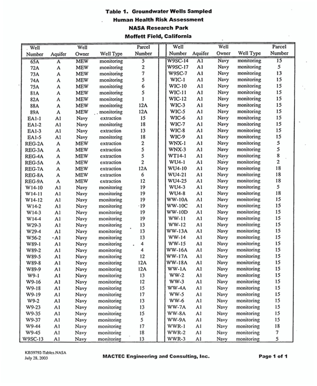
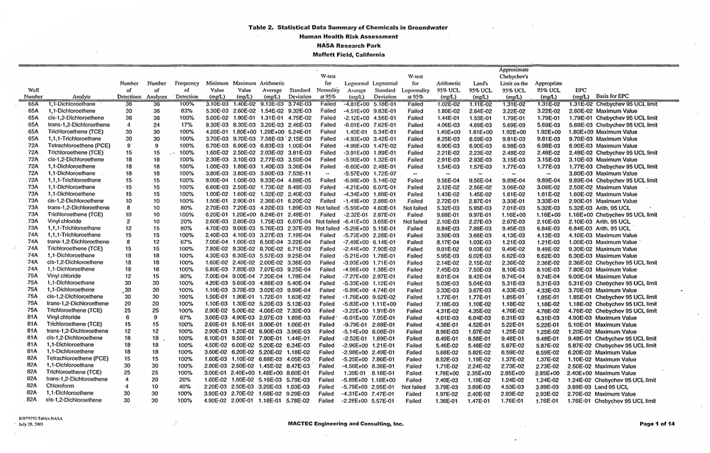
2
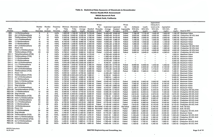
3
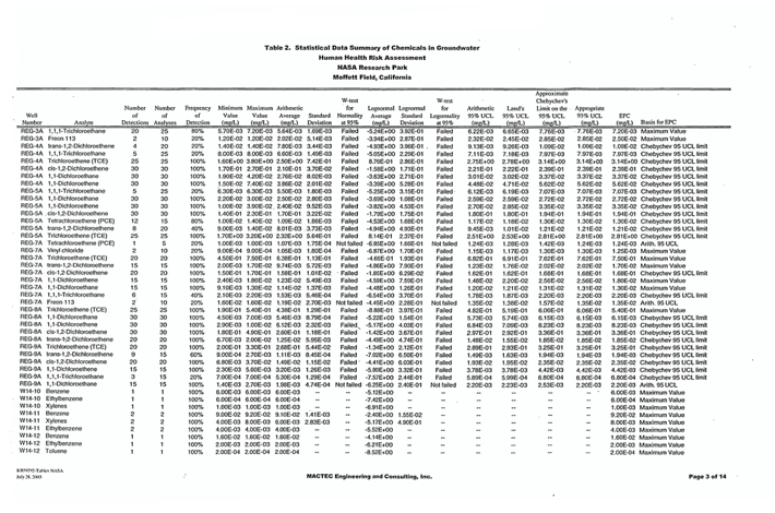
4
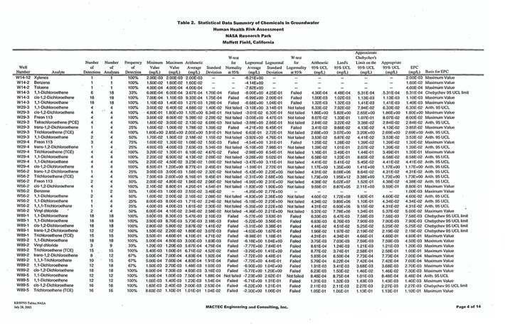
5
6
7
8
9
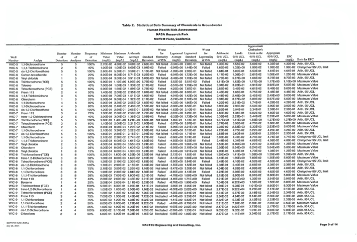
10
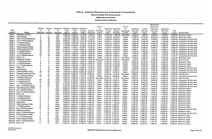
11
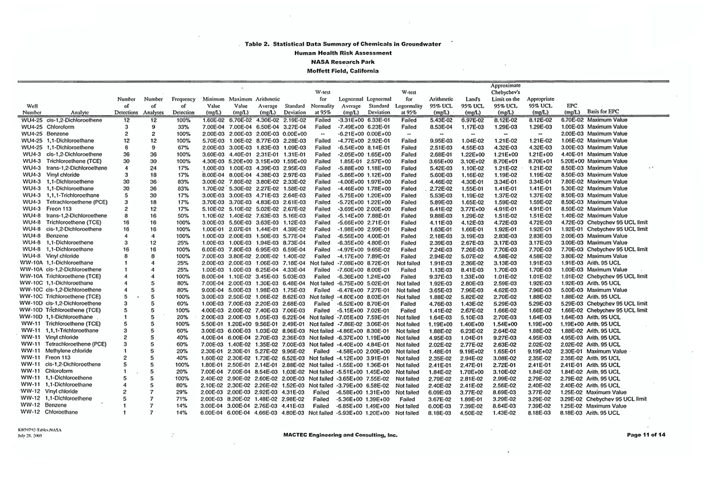
12
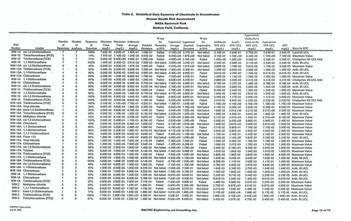
13
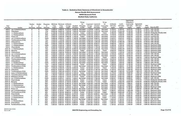
14
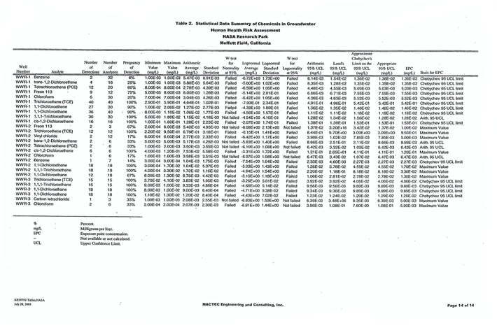
15

16
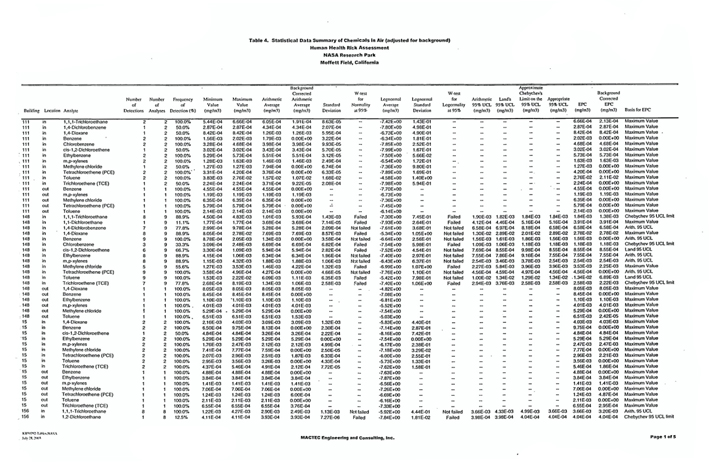
17
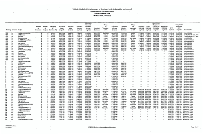
18
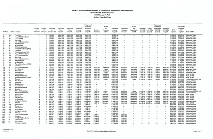
19
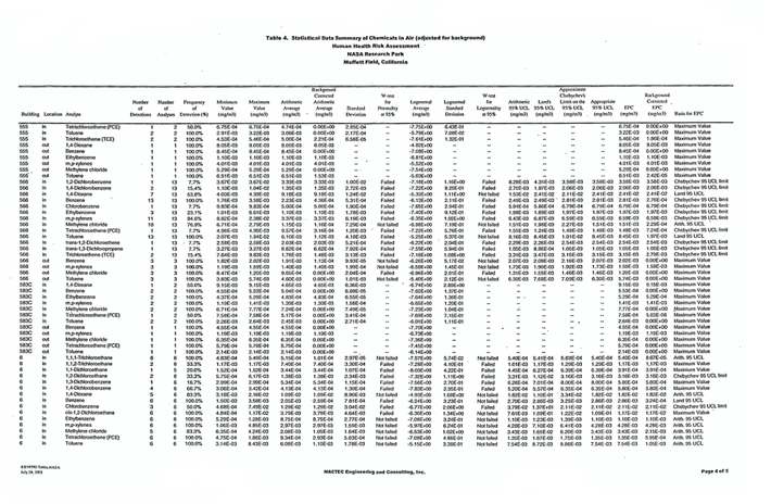
20
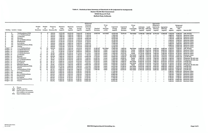
21
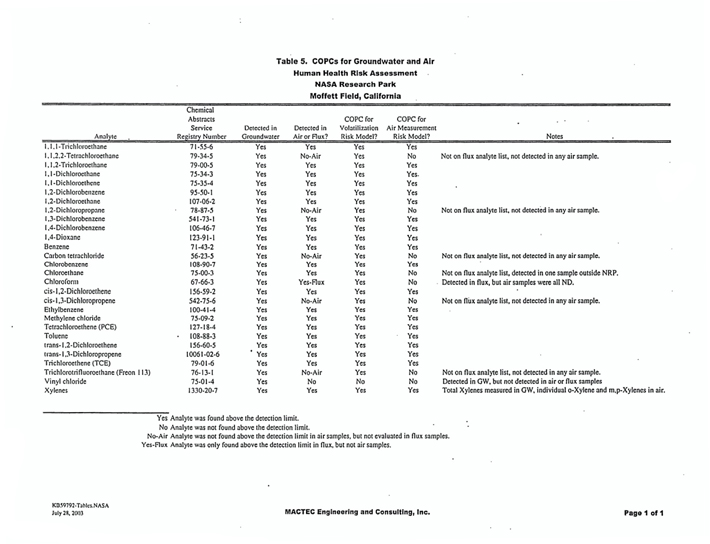
22
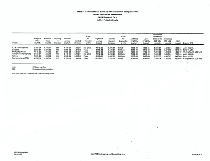
23
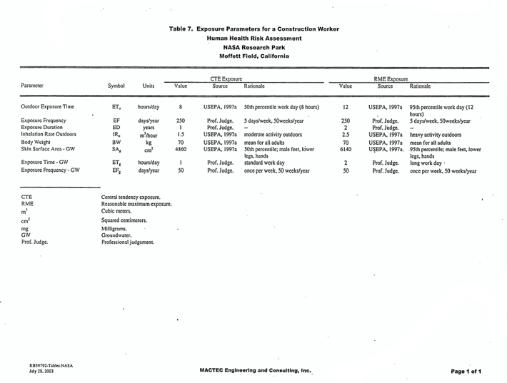
24
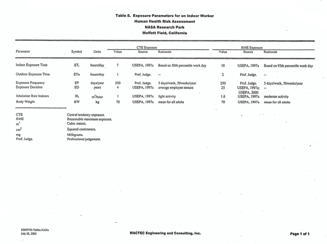
25
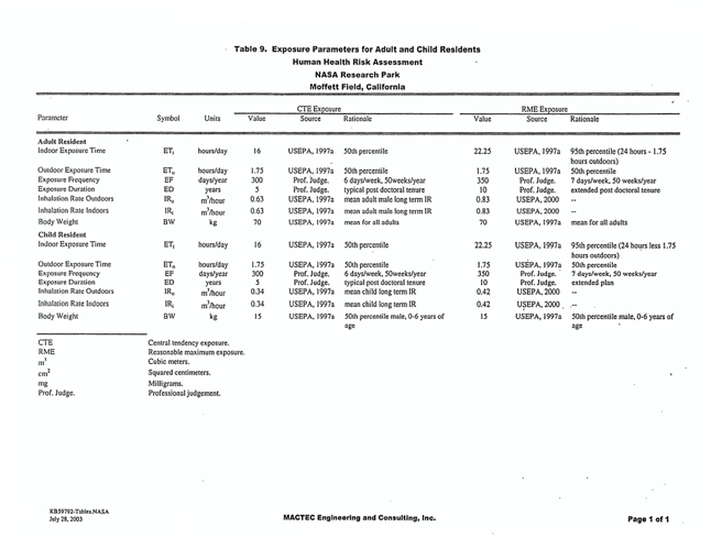
26
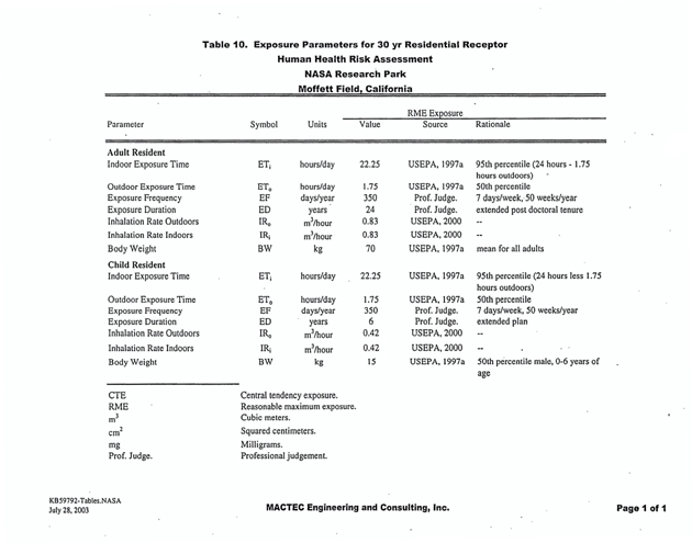
27
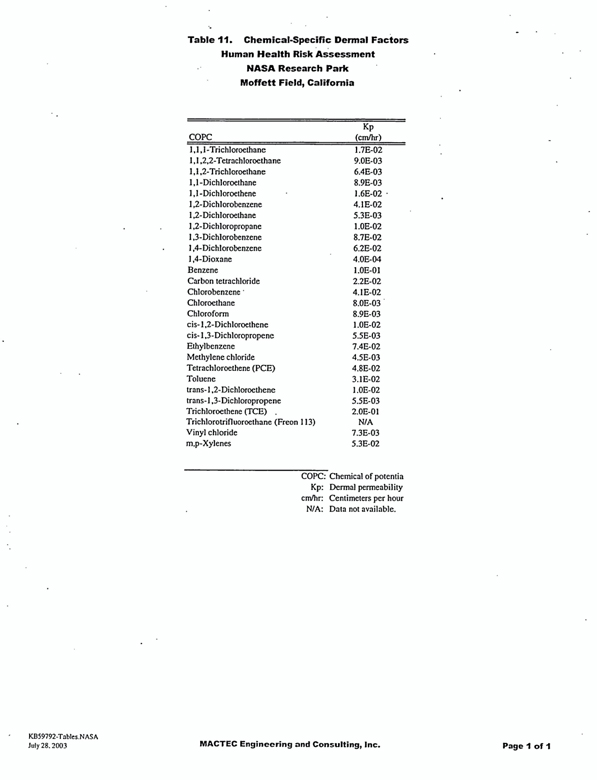
28
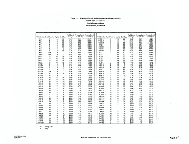
29
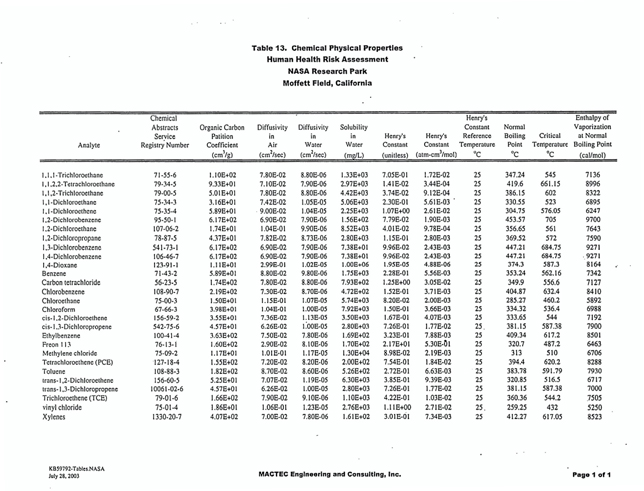
30
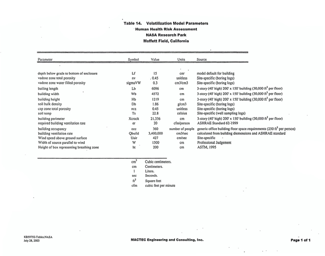
31
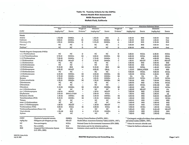
32
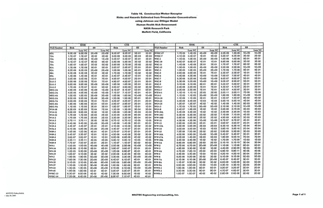
33
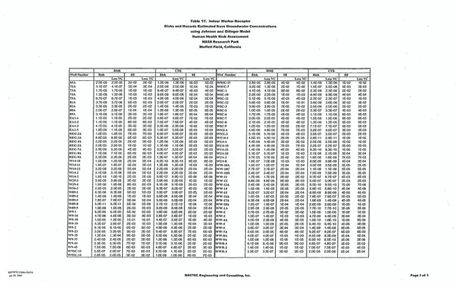
34
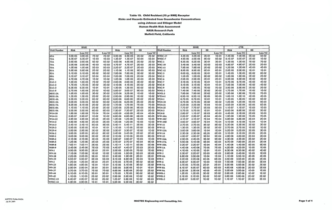
35
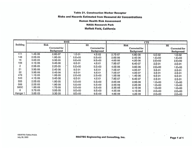
36
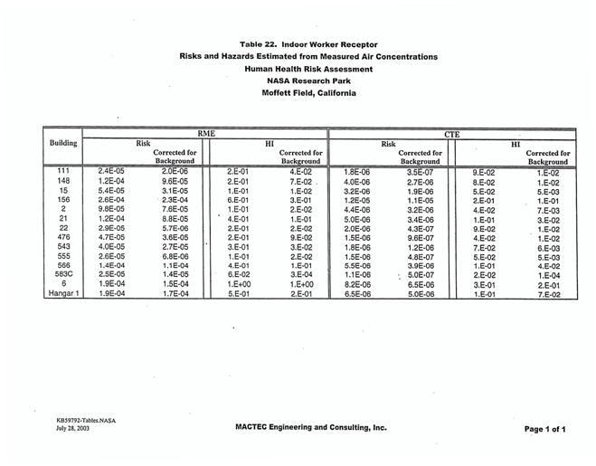
37
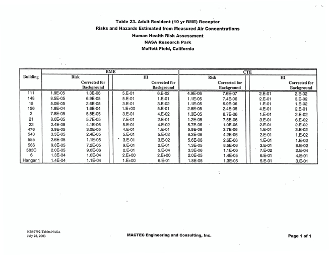
38
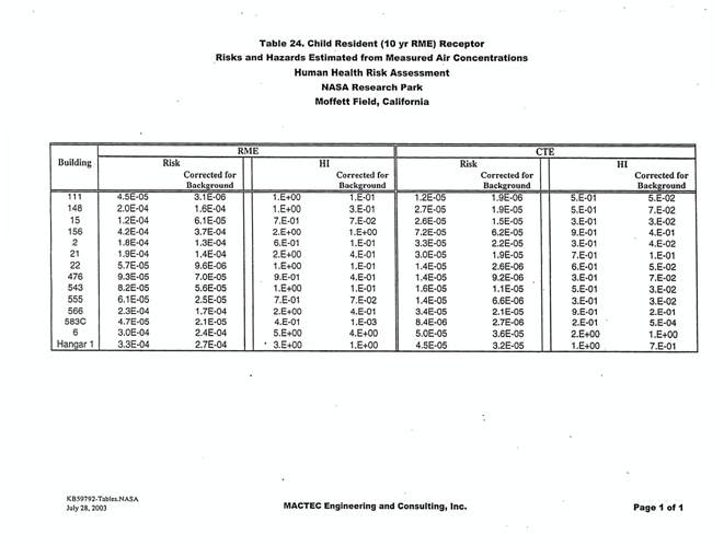
39
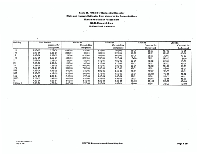
40
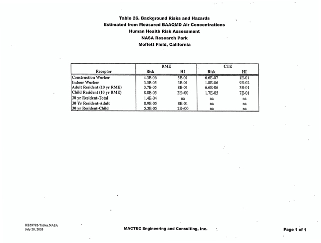
41
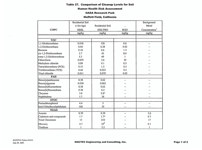
42
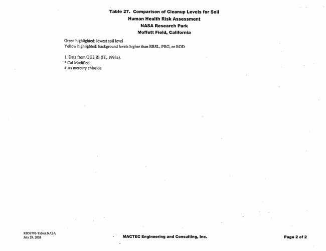
43
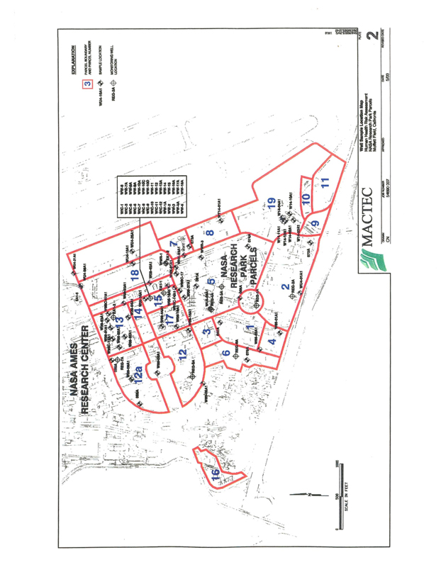
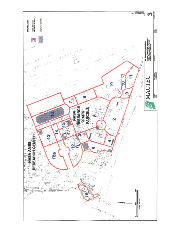
2
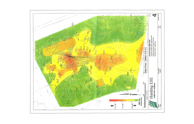
3
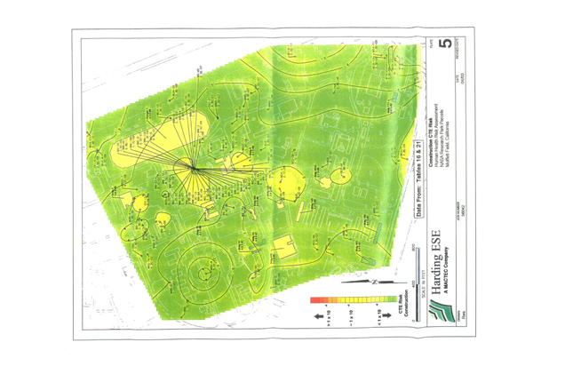
4
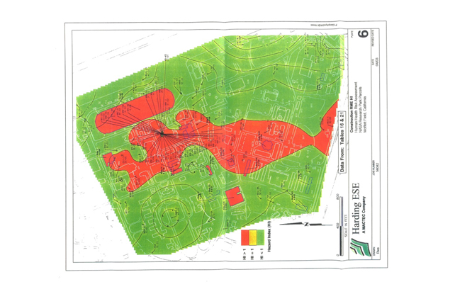
5
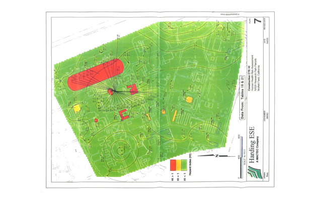
6
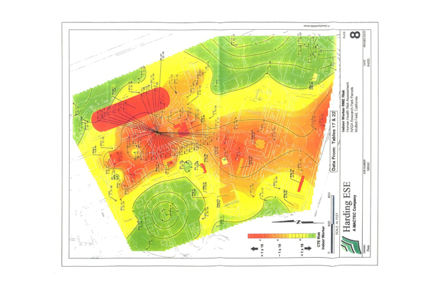
7
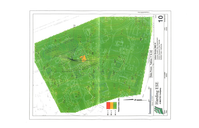
8
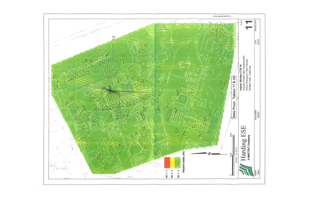
9
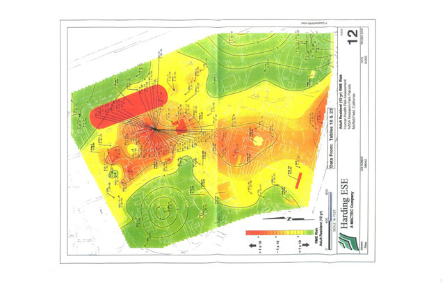
10
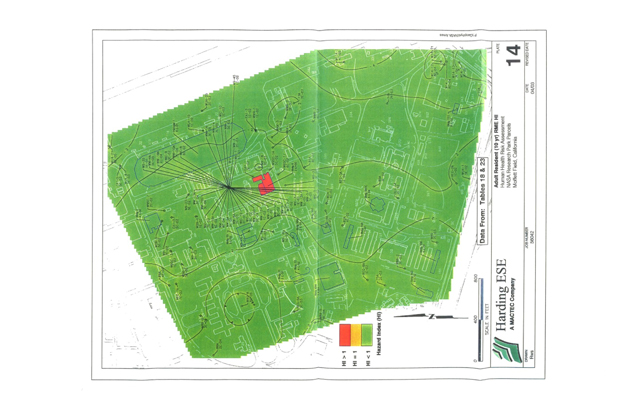
11
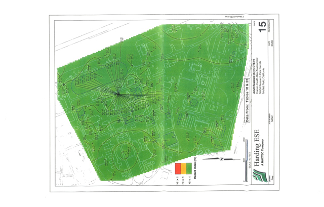
12
ENVIRONMENTAL ISSUES
MANAGEMENT PLAN
NASA Research Park
Santa Xxxxx County, California
DRAFT FINAL
30 July 2004
Prepared for:
DMJM
000 Xxxxxxx Xxxxxx, Xxxxx Xxxxx
San Francisco, California 94111
Prepared by:
Xxxxx & Xxxxxxxxxx, Inc.
0000 Xxxxx Xxxxx
Burlingame, California 94010
EKI A20044.00
ENVIRONMENTAL ISSUES MANAGEMENT PLAN
NASA Research Park
Santa Xxxxx County, California
TABLE OF CONTENTS
| EXECUTIVE SUMMARY |
ES-1 | |||||||||||
| 1. |
INTRODUCTION |
1-1 | ||||||||||
| 1.1. | Representations |
1-1 | ||||||||||
| 1.2. | Responsibilities |
1-2 | ||||||||||
| 2. |
SITE BACKGROUND |
2-1 | ||||||||||
| 2.1. | Site Setting |
2-1 | ||||||||||
| 2.1.1. | Hydrogeology |
2-1 | ||||||||||
| 2.2. | Site History |
2-2 | ||||||||||
| 2.3. | Summary of Known Site Environmental Conditions and Potential Chemicals of Concern |
2-2 | ||||||||||
| 2.4. | Summary of Site Investigations and Remedial Actions |
2-4 | ||||||||||
| 2.4.1. |
Available Documents |
2-4 | ||||||||||
| 2.4.1.1. | Environmental Baseline Survey |
2-4 | ||||||||||
| 2.4.1.2. | Closure Plans |
2-5 | ||||||||||
| 2.4.2. | Installation Restoration Program |
2-5 | ||||||||||
| 2.4.3. | West Side Aquifer Groundwater Contamination |
2-6 | ||||||||||
| 2.4.4. | Installation Restoration Program Sites |
2-8 | ||||||||||
| 2.4.4.1. | IRP Site 10 (Chase Park) |
2-9 | ||||||||||
| 2.4.4.2. | IRP Site 14-North |
2-9 | ||||||||||
| 2.4.4.3. | IRP Site 16 (Sump 60) |
2-9 | ||||||||||
| 2.4.4.4. | IRP Site 17 (Sump 61) |
2-10 | ||||||||||
| 2.4.4.5. | IRP Site 18 |
2-10 | ||||||||||
| 2.4.5. | Petroleum Sites |
2-11 | ||||||||||
| 2.4.5.1. | Naval Exchange Gasoline Service Station |
2-12 | ||||||||||
| 2.4.5.2. | IRP Site 9 |
2-13 | ||||||||||
| 2.4.5.3. | IRP Site 14-South |
2-14 | ||||||||||
| 2.4.5.4. | IRP Site 15 |
2-14 | ||||||||||
| 2.4.5.5. | IRP Site 19 |
2-15 | ||||||||||
| 2.4.5.6. | IRP Site 24 |
2-16 | ||||||||||
| 2.4.6. | Survey of Lead in Soil | 2-16 | ||||||||||
| 2.5. | Summary of Existing Subsurface Structures That May Require Removal |
2-18 | ||||||||||
i
ENVIRONMENTAL ISSUES MANAGEMENT PLAN
NASA Research Park
Santa Xxxxx County, California
| 2.6. | Summary of Hazardous Materials Associated With Existing Structures And Current Operations |
2-18 | ||||||||||
| 2.6.1. | Asbestos-Containing Materials |
2-18 | ||||||||||
| 2.6.2. | Lead-Based Paints |
2-19 | ||||||||||
| 2.6.3. | PCBs in Equipment and Building Materials |
2-19 | ||||||||||
| 2.6.4. | Other Hazardous Materials and Hazardous Waste |
2-20 | ||||||||||
| 3. |
PLANNED DEVELOPMENT OF NASA RESEARCH PARK |
3-1 | ||||||||||
| 3.1. |
Current Land Use |
3-1 | ||||||||||
| 3.2. |
Planned Land Use |
3-1 | ||||||||||
| 4. |
REVISED HUMAN HEALTH RISK ASSESSMENT AND DEVELOPMENT OF SOIL TARGET CONCENTRATION LEVELS |
4-1 | ||||||||||
| 4.1. | Potential Exposure Pathways |
4-1 | ||||||||||
| 4.2. | NRP Revised Human Health Risk Assessment |
4-2 | ||||||||||
| 4.2.1. |
Scope of Revised HHRA |
4-2 | ||||||||||
| 4.2.2. |
Results of Revised Human Health Risk Assessment |
4-3 | ||||||||||
| 4.3. | Development of Soil Target Concentration Levels |
4-4 | ||||||||||
| 4.3.1. |
RWQCB ESLs |
4-4 | ||||||||||
| 4.3.2. |
U.S. EPA PRGs |
4-5 | ||||||||||
| 4.3.3. |
MEW ROD |
4-5 | ||||||||||
| 4.3.4. |
Navy Action Levels and Risk-Based Screening Levels for Petroleum Products and Constituents |
4-5 | ||||||||||
| 4.3.4.1. | Action Levels for Petroleum Products and Constituents |
4-5 | ||||||||||
| 4.3.4.2. | Current Approach to Assessment of Former NAS Xxxxxxx Field Petroleum Sites |
4-6 | ||||||||||
| 4.3.4.3. | Navy Risk Assessment of Former NAS Xxxxxxx Field Petroleum Site 9 |
4-6 | ||||||||||
| 4.3.5. |
Background Metals Concentrations |
4-7 | ||||||||||
| 4.4. | Risk Goals for NRP |
4-7 | ||||||||||
| 5. |
RISK MANAGEMENT DESIGN CONSIDERATIONS FOR NEW CONSTRUCTION AND EXISTING BUILDINGS |
5-1 | ||||||||||
| 5.1. | Measures to Address VOC Vapor Intrusion into New Construction and Existing Buildings |
5-1 | ||||||||||
| 5.1.1. |
The Vapor Intrusion Process |
5-1 | ||||||||||
| 5.1.2. |
Vapor Intrusion Mitigation Area |
5-2 | ||||||||||
| 5.1.2.1. |
Evaluation of Vapor Intrusion at 5 ug/L TCE in Groundwater |
5-3 | ||||||||||
| 5.1.2.2. |
Conservative Nature of 5 ug/L TCE Criterion |
5-6 | ||||||||||
ii
ENVIRONMENTAL ISSUES MANAGEMENT PLAN
NASA Research Park
Santa Xxxxx County, California
| 5.1.3. |
Vapor Intrusion Mitigation Measures |
5-6 | ||||||||||
| 5.1.3.1. | Design Guidance for Vapor Intrusion Mitigation |
5-6 | ||||||||||
| 5.1.3.2. | Active Sub-Slab Depressurization (SSD) |
5-7 | ||||||||||
| 5.1.3.3. | Continuous Positive-Pressure Ventilation (PPV) |
5-8 | ||||||||||
| 5.1.3.4. | Ventilated Parking Garage Construction |
5-9 | ||||||||||
| 5.1.3.5. | Sub-Membrane Depressurization (SMD) for Crawl Spaces |
5-10 | ||||||||||
| 5.1.3.6. | Vapor Intrusion Barrier |
5-10 | ||||||||||
| 5.1.3.7. | Sealing Cracks and Utility Penetrations in the Floor |
5-11 | ||||||||||
| 5.1.3.8. | Mitigating Vapor Intrusion in Existing Buildings |
5-11 | ||||||||||
| 5.1.4. | Design of Vapor Intrusion Mitigation Measures |
5-11 | ||||||||||
| 5.1.5. | Monitoring Vapor Intrusion Mitigation Effectiveness |
5-12 | ||||||||||
| 5.2. | Reducing the Potential for Lateral Migration of VOCs in Utility Corridors |
5-12 | ||||||||||
| 5.2.1. | Utilities Subject To Mitigation Measures |
5-12 | ||||||||||
| 5.2.2. | Measures to Mitigate Groundwater Movement in Utility Backfill |
5-13 | ||||||||||
| 5.2.3. | Measures to Reduce Groundwater Infiltration into Utility Pipes |
5-13 | ||||||||||
| 5.2.4. | Design of Utility Lines |
5-14 | ||||||||||
| 5.2.5. | Soil and Groundwater Handling During Utility Line Construction |
5-14 | ||||||||||
| 5.3. | Reducing the Potential for Creating Conduits to Deeper Groundwater Zones During Pile or Elevator Shaft Installation |
5-14 | ||||||||||
| 5.4. | Removal or Relocation/Replacement of Existing Groundwater Monitoring Xxxxx and Remediation System Pipelines |
5-15 | ||||||||||
| 5.4.1. | NASA Agreements Relating to Coordination of NRP Development with the Navy and MEW Companies’ Groundwater Remediation Systems |
5-15 | ||||||||||
| 5.4.2. | Pre-Construction Coordination |
5-16 | ||||||||||
| 6. |
RISK MANAGEMENT DURING CONSTRUCTION |
6-1 | ||||||||||
| 6.1. |
General Approach for Conducting Environmental Sampling and Treatment/Disposal of Impacted Material During Site Development |
6-1 | ||||||||||
| 6.1.1. |
Environmental Sampling |
6-2 | ||||||||||
| 6.1.2. |
Excavation or Removal of Impacted Soil or Groundwater and Other Materials Relating to Potential Chemical Impacts |
6-2 | ||||||||||
| 6.1.3. |
Treatment or Disposal of Impacted Soil and Groundwater, Tanks, Sumps, Abandoned Pipes or Chemical Containers |
6-2 | ||||||||||
| 6.2. | Site-Specific Health And Safety Worker Planning Requirements |
6-3 | ||||||||||
| 6.2.1. |
Planning Requirements for Contractors |
6-3 | ||||||||||
| 6.2.2. |
Worker Training |
6-4 | ||||||||||
| 6.2.3. |
Components of the Health and Safety Plan |
6-4 | ||||||||||
| 6.3. | Construction Impact Mitigation Measures |
6-8 | ||||||||||
| 6.3.1. | Dust Control Measures |
6-8 | ||||||||||
iii
ENVIRONMENTAL ISSUES MANAGEMENT PLAN
NASA Research Park
Santa Xxxxx County, California
| 6.3.2. | Decontamination |
6-9 | ||||||||||
| 6.3.3. | Storm Water Pollution Controls |
6-9 | ||||||||||
| 6.3.4. | Dewatering |
6-10 | ||||||||||
| 6.4. |
Management of Asbestos Containing Debris |
6-12 | ||||||||||
| 6.5. |
Management of Debris Containing Lead-Based Paint |
6-13 | ||||||||||
| 6.6. |
Removal of PCB-Containing Equipment |
6-13 | ||||||||||
| 6.7. |
Management of Abandoned Underground Storage Tanks, Sumps, and Buried Drums and Containers |
6-13 | ||||||||||
| 6.8. |
Management of Abandoned Pipes |
6-15 | ||||||||||
| 6.9. |
Protection and Removal/Relocation of Monitoring Xxxxx and Remediation System Components |
6-15 | ||||||||||
| 6.9.1. | Removal or Relocation of Remediation System Components |
6-16 | ||||||||||
| 6.9.2. | Protection of Groundwater Xxxxx and Remediation System Components |
6-16 | ||||||||||
| 6.9.3. | Shutdown of Remediation Systems |
6-16 | ||||||||||
| 6.9.4. | Remediation System Access |
6-17 | ||||||||||
| 6.9.5. | Accidental Releases of Untreated Groundwater |
6-17 | ||||||||||
| 6.10. |
Soil Management Protocols |
6-18 | ||||||||||
| 6.10.1. | Lead-Impacted Soil |
6-18 | ||||||||||
| 6.10.1.1. |
Lead-Based Paint Survey |
6-19 | ||||||||||
| 6.10.1.2. |
Initial Soil Lead Assessment |
6-19 | ||||||||||
| 6.10.1.3. |
Excavation and Disposal of Lead-Impacted Soil |
6-21 | ||||||||||
| 6.10.2. | Excavated Soil Screening Procedures |
6-21 | ||||||||||
| 6.10.2.1. |
Field Headspace Soil Screening Method |
6-23 | ||||||||||
| 6.10.2.2. |
Notification of Soil Containing Chemicals and Impacted Soil |
6-23 | ||||||||||
| 6.10.2.3. |
Documentation of Soil Screening & Management of Impacted Soils |
6-24 | ||||||||||
| 6.10.3. |
Management of Impacted Excavated Soils |
6-25 | ||||||||||
| 6.10.4. | Soil Re-Use On-Site |
6-26 | ||||||||||
| 6.10.5. | Contingency Actions for the Observation, Investigation, and Removal of Unnaturally Stained, Discolored, or Odorous Soil |
6-26 | ||||||||||
| 6.10.5.1. |
Managing Soil Impacted by COPCs Other Than VOCs or TPH |
6-27 | ||||||||||
| 6.10.5.2. |
Management of Impacted Soils After Construction Excavation is Complete |
6-27 | ||||||||||
| 6.10.5.3. |
Documentation of Contingency Actions Taken |
6-32 | ||||||||||
| 7. |
POST-CONSTRUCTION AND LONG-TERM RISK MANAGEMENT |
7-1 | ||||||||||
| 7.1. | Property Manager and Tenant Notification | 7-1 | ||||||||||
iv
ENVIRONMENTAL ISSUES MANAGEMENT PLAN
NASA Research Park
Santa Xxxxx County, California
| 7.2. | Maintaining Planned Land Use |
7-2 | ||||||||
| 7.3. | Prohibiting Use of Site Groundwater |
7-2 | ||||||||
| 7.4. | Protocols for Future Subsurface Activities |
7-2 | ||||||||
| 7.5. | Long-Term Compliance; Periodic Review and Update of EIMP |
7-3 | ||||||||
| 7.5.1. | Evaluation of Groundwater Monitoring Data |
7-3 | ||||||||
| 7.5.2. | Inspections/Maintenance/Monitoring |
7-3 | ||||||||
| 8. |
REFERENCES |
8-1 | ||||||||
LIST OF TABLES
| 1. | Environmental Documents Supporting the Development of NASA Research Park |
|||
| 2. | Summary of Closure Plans |
|||
| 3. | Volatile Organic Compounds Detected in Groundwater |
|||
| 4. | Soil Target Concentration Levels for Polynuclear Aromatic Hydrocarbons (PAHs), Semi-Volatile Organic Compounds (SVOCs), Polychlorinated Biphenyls, and Metals |
|||
| 5. | Soil Target Concentration Levels for Chlorinated VOCs, Petroleum Hydrocarbons, Benzene, Toluene, Ethylbenzene, and Xylenes |
|||
v
ENVIRONMENTAL ISSUES MANAGEMENT PLAN
NASA Research Park
Santa Xxxxx County, California
LIST OF FIGURES
| 1. | Site Location |
|||
| 2. | Planned Land Use and Environmental Baseline Survey Study Areas |
|||
| 3. | Installation Restoration Program Site Locations |
|||
| 4. | Trichloroethene Concentrations Detected in Groundwater (ug/L) |
|||
| 5. | Regional Groundwater Remediation Program Treatment System Layout |
|||
| 6. | TPH as Gasoline in Groundwater (ug/L), Approximate Concentration Contours |
|||
| 7. | Benzene Concentrations Detected in Groundwater (ug/L) |
|||
| 8. | Generalized Vapor Intrusion Process |
|||
| 9. | Vapor Intrusion Mitigation Area |
|||
| 10. | Generalized Layout of Sub-Slab Depressurization System |
|||
| 11. | Decision Diagram for Pre-Construction Planning of Potential Modifications to Remediation Systems |
|||
| 12. | Decision Diagram for Management of Dewatering Water |
|||
| 13. | Decision Diagram for Management of Drums, Containers, Tanks, or Sumps |
|||
| 14. | Decision Diagram for Abandoned Pipe Management During Construction |
|||
| 15. | Decision Diagram for Remediation System Protection During Construction |
|||
| 16. | Decision Diagram for Management of Excavated Soil in MEW Allocation Area |
|||
| 17. | Decision Diagram for Management of Excavated Soil in Navy Allocation Area |
|||
| 18. | Decision Diagram for Management of Lead-Impacted Soil |
|||
| 19. | Decision Diagram for Unnaturally Stained, Discolored or Odorous Soil Management |
|||
vi
ENVIRONMENTAL ISSUES MANAGEMENT PLAN
NASA Research Park
Santa Xxxxx County, California
LIST OF APPENDICES
| A. | MEW Companies/Navy/NASA Allocation Area Map |
| B. | Mitigated Alternative 5 Land Use Plan from Final Programmatic Environmental Impact Statement, prepared by DCE, July 2002 |
| C. | Selected Plates from the Revised Human Health Risk Assessment, NASA Research Park, Xxxxxxx Field, California, prepared by Mactec, Inc., 28 July 2003 |
| D. | Draft Agreement for Coordination of Construction and MEW Remedial System Modification Work at NASA Research Park, Xxxx Research Center, Xxxxxxx Field, California |
| E. | Draft Agreement for Coordination of Construction and Navy Remedial System Modification Work, NASA Research Park, Xxxx Research Center, Xxxxxxx Field, California |
vii
ENVIRONMENTAL ISSUES MANAGEMENT PLAN
NASA Research Park
Santa Xxxxx County, California
LIST OF ACRONYMS / ABBREVIATIONS
| ACM | asbestos-containing materials | |
| ARC | Xxxx Research Center | |
| AST | aboveground storage tank | |
| BAAQMD | Bay Area Air Quality Management District | |
| bgs | below ground surface | |
| BMPs | best management practices | |
| BRAC | Base Realignment and Closure | |
| BTEX | benzene, toluene, ethylbenzene and xylenes | |
| Cal/EPA | California Environmental Protection Agency | |
| CBC | California Building Code | |
| CDF | controlled density fill | |
| CERCLA | Comprehensive Environmental Response, Compensation, and Liability Act | |
| cis-1,2-DCE | cis-1,2-dichloroethene | |
| COPC | chemical of potential concern | |
| CTE | Central Tendency Estimate | |
| CWMI | Chemical Waste Management, Inc. | |
| 1,1-DCA | 1,1-dichloroethane | |
| 1,2-DCA | 1,2-dichloroethane | |
| 1,1-DCE | 1,1-dichloroethene | |
| DERP | Defense Environmental Restoration Program | |
| DHS | Department of Health Services | |
| XXXX | Xxxxxx, Xxxx, Xxxxxxx, & Xxxxxxxxxx | |
| XxX | Department of the Navy | |
| DTSC | Department of Toxic Substances Control | |
| EBS | Environmental Baseline Survey | |
| EIMP | Environmental Issues Management Plan | |
| EIS | Environmental Impact Statement | |
| EKI | Xxxxx & Xxxxxxxxxx, Inc. | |
| ESL | Environmental Screening Level | |
| FFA | Federal Facility Agreement | |
| FID | flame-ionization detector | |
| GAC | granular activated carbon | |
| GWTS | groundwater treatment system | |
| Xxxxxxx | Xxxxxxx ESE, Inc. | |
| hazwoper | hazardous waste site operations | |
| HDPE | high-density polyethylene | |
| HHRA | human health risk assessment | |
| HI | Hazard Index | |
| H&SP | health and safety plan | |
| IRP | Installation Restoration Program | |
| LCM | lead-containing material | |
| LTA | lighter-than-air | |
| Mactec | Mactec, Inc. | |
| MCL | maximum contaminant level | |
| MEW | Middlefield-Xxxxx-Xxxxxxx | |
| MFA | Xxxxxxx Federal Airfield | |
| mg/kg | milligrams per kilogram | |
| NADP EIS | NASA Xxxx Development Plan Environmental Impact Statement | |
| NASA | National Aeronautics and Space Administration |
viii
ENVIRONMENTAL ISSUES MANAGEMENT PLAN
NASA Research Park
Santa Xxxxx County, California
| NAS Xxxxxxx Field | Naval Air Station Xxxxxxx Field | |
| NEX service station | Naval Exchange Gasoline Service Station | |
| NPDES | National Pollutant Discharge Elimination System | |
| NPL | National Priorities List | |
| NRP | NASA Research Park | |
| OVA | organic vapor analyzer | |
| PCB | Polychlorinated biphenyl | |
| PCE | tetrachloroethene | |
| PEL | Permissible Exposure Limit | |
| PID | photo-ionization detector | |
| POTW | Publicly-Owned Treatment Works | |
| ppb | parts per billion | |
| PPE | personal protective equipment | |
| ppm | parts per million | |
| ppmv | parts per million by volume | |
| PPV | positive-pressure ventilation | |
| PRG | Preliminary Remediation Goal | |
| QSI | Quantum Services Inc. | |
| RBCA | risk-based corrective action | |
| RBSL | risk-based screening levels | |
| RI/FS | Remedial Investigation/Feasibility Study | |
| RME | Reasonable Maximum Exposure | |
| ROD | Record of Decision | |
| RWQCB | California Regional Water Quality Control Board, San Francisco Bay Region | |
| SCCEHD | Santa Xxxxx County Environmental Health Department | |
| SCVWD | Santa Xxxxx Valley Water District | |
| Site | 213-acre parcel that was formerly part of Naval Air Station Xxxxxxx Field in Santa Xxxxx County, California | |
| SMD | sub-membrane depressurization | |
| SSD | sub-slab depressurization | |
| STLC | Soluble Threshold Limit Concentration | |
| SVOC | semi-volatile organic compound | |
| SWPPP | Storm Water Pollution Prevention Plan | |
| SWRCB | State Water Resources Control Board | |
| 1,1,1-TCA | 1,1,1-trichloroethane | |
| TCE | trichloroethene | |
| TCL | target concentration level | |
| TCRA | Time-Critical Removal Action | |
| TPH | total petroleum hydrocarbons | |
| TPHd | total petroleum hydrocarbons as diesel | |
| TPHg | total petroleum hydrocarbons as gasoline | |
| TPH-e | extractable total petroleum hydrocarbons | |
| TPH-p | purge able total petroleum hydrocarbons | |
| TSCA | Toxic Substances Control Act | |
| TTO | total toxic organics | |
| trans-1,2-DCE | trans-1,2-dichloroethene | |
| TTLC | Total Threshold Limit Concentration | |
| ug/L | micrograms per liter | |
| ug/m3 | micrograms per cubic meter | |
| U.S. EPA | U.S. Environmental Protection Agency |
ix
ENVIRONMENTAL ISSUES MANAGEMENT PLAN
NASA Research Park
Santa Xxxxx County, California
| UST | underground storage tank | |
| VOC | volatile organic compound | |
| WATSL | West-Side Aquifers Treatment System | |
| Xxxxxx | Xxx X. Xxxxxx | |
| WET | Waste Extraction Test |
x
EXECUTIVE SUMMARY
The National Aeronautics and Space Administration (“NASA”) plans to develop a world- class collaborative research and educational campus at the NASA Research Park (“NRP”), a 213-acre parcel that was formerly part of Naval Air Station Xxxxxxx Field in Santa Xxxxx County, California (“Site”; Figure 1). Soil and groundwater quality at the NRP have been impacted by the historical use of the Site by the Navy, as well as by the migration of groundwater containing chlorinated volatile organic compounds (“VOCs”) from the upgradient Middlefield-Xxxxx-Xxxxxxx (“MEW”) Superfund Site located south of the NRP in the City of Mountain View. To manage the planned redevelopment of the NRP, NASA intends to partner with one or more organizations that have expertise with building rehabilitation and development.
This Environmental Issues Management Plan (“EIMP”) provides a decision framework for the management of residual chemicals in soil and groundwater at the Site during development. The EIMP is intended to describe procedures to address the known remaining environmental conditions at the Site, as well as contingency actions to be taken in the event that previously unknown environmental conditions are encountered during development of the NRP. The EIMP will be provided to the U.S. Environmental Protection Agency (“U.S. EPA”) and the California Regional Water Quality Control Board, San Francisco Bay Region (“RWQCB”) as lead agencies for the Site, and other involved regulatory agencies with oversight authority to obtain regulatory approval of the measures to be taken during Site development to address Site environmental conditions. By obtaining regulatory pre-approval of procedures to be followed if impacted soil and groundwater are encountered during Site development activities, the potential for delays due to environmental conditions can be reduced.
The EIMP provides a baseline of minimum design considerations for new construction, risk management measures to be implemented during construction at the Site, post-construction risk management procedures for future subsurface activities at the Site, as well as procedures for long-term compliance with this EIMP. All NASA partners, tenants, project developers and other entities with responsibility for Site activities shall have the independent obligation to: 1) review available information concerning Site environmental conditions; 2) determine the adequacy of this EIMP with respect to the expected Site conditions and the intended land use, as well as the conditions actually encountered during Site development; 3) establish management procedures to ensure that risk management measures are properly implemented and maintained; 4) comply with applicable policies, laws and regulations; and 5) evaluate the current understanding of the health effects of identified chemicals of potential concern (“COPCs”), to the extent the understanding of health effects assumed in this EIMP may change.
Existing Environmental Conditions
Numerous potential source areas have been investigated and remediated within the NRP area, primarily releases associated with underground storage tanks (“USTs”) and sumps that contained petroleum hydrocarbon products, although several source areas of chlorinated VOC contamination have also been investigated and remediated by the Navy.
A large regional plume of chlorinated VOCs underlies most of the NRP area. The source of this contamination is migration of contaminated groundwater from the upgradient MEW Superfund
ES-1
Site that has commingled with groundwater contamination from chlorinated solvent sources locked within the NRP area. In addition, petroleum hydrocarbons and fuel-related constituents, such as benzene, toluene, ethylbenzene and xylene (“BTEX”), from sources at Xxxxxxx Field have also impacted Site groundwater. Both the Navy and the companies remediating the MEW Superfund site (“MEW Companies”) have installed and are operating groundwater remediation systems within the NRP area.
As a result of investigations that were performed at the Site, the identified environmental conditions and primary COPCs that need to be considered during redevelopment are:
| • | the presence of chlorinated VOCs in Site groundwater and in Site soil; |
| • | the presence of total petroleum hydrocarbons and other fuel-related constituents, including BTEX compounds, in Site groundwater and in Site soil; |
| • | the presence of elevated concentrations of polychlorinated biphenyls (“PCBs”) in soil surrounding buildings; and |
| • | the presence of elevated concentrations of lead in soil surrounding buildings. |
Other site conditions that must be considered during redevelopment include existing subsurface structures (e.g., sumps or tanks) that need to be removed and hazardous materials associated with existing buildings (e.g., asbestos-containing materials).
Human Health Risk Assessment
Mactec, Inc. (“Mactec”) prepared a Human Health Risk Assessment (“HHRA”), dated 28 July 2003, to evaluate potential human health effects from possible exposure to hazardous chemicals in groundwater and air at the Site (Mactec, 2003b). Based on NASA’s planned land use for the NRP area, potential future receptors identified in the HHRA include (a) construction workers; (b) indoor workers, such as researchers, teachers, office personnel; and (c) adult and child residents in housing provided for students or employees and their families. For the adult and child residents, exposures were assessed in two ways, i.e., assuming a typical 5- to 10-year residence at the Site, and assuming a 30-year residence at the Site, which is consistent with default exposure parameters in U.S. EPA risk assessment guidance.
Potential future receptors may be exposed to COPCs by one or more of the following pathways:
| • | inhalation of volatile chemicals from groundwater or soil; |
| • | dermal absorption due to direct soil and/or groundwater contact; |
| • | inhalation of airborne suspended soil particulates; and |
| • | incidental soil ingestion. |
To provide a range of risk estimates, two types of exposure scenarios were used in the HHRA, i.e., a reasonable maximum exposure (“RME”) and a central tendency exposure (“CTE”). The
ES-2
RME, as defined by U.S. EPA (1989b), is the “highest exposure that is reasonably expected to occur” and is estimated using a combination of average and upper-bound values of human exposure parameters. The CTE provides an estimate for exposure at a site by the use of average or site-related exposure parameters (Mactec, 2003b).
Groundwater is the primary contaminated medium of concern at the Site. Exposure to chemicals in the groundwater is primarily the result of transport of VOC vapors from the groundwater to the ground surface. Once at the surface, these VOC vapors enter the outdoor atmosphere or can infiltrate the indoor building environment. The risks resulting from potential exposure to VOC vapors were calculated using both groundwater quality data and air quality data (Mactec, 2003b).
For each receptor population, estimated human health risks were calculated (a) for each of the 90 groundwater sampling locations in the upper aquifer at the Site, based on chemical concentrations detected in groundwater samples collected from each well, and (b) for each of 14 existing buildings, based on chemical concentrations detected in air samples collected inside and outside each building. The calculated human health risks for indoor workers and residents are shown in Appendix C on selected figures from the HHRA (Mactec, 2003b). Each figure presents the estimated human health risk for each groundwater sampling location and each building for which risks were calculated. Contours are drawn on each figure to indicate how estimated human health risks based on groundwater data vary spatially across the Site.
Human health risks are expressed as either (a) an incremental lifetime excess cancer risk or (b) a Hazard Index (“HI”) for non-cancer adverse health affects. Based on U.S. EPA guidance, cancer risks are compared in the HHRA to a risk management range of 10-6 (one-in-a-million) to 10-4 (one-in-ten-thousand), and the non-cancer HI is compared to a threshold level of 1.0, a level below which there are unlikely to be adverse health affects, even for sensitive populations (Mactec, 2003b).
For the purpose of developing this EIMP, conclusions from the HHRA can be summarized as follows:
| • | for future building occupants at the Site, results from the HHRA indicate that VOC vapors may potentially migrate from groundwater to indoor air inside buildings at levels of concern, a process called “vapor intrusion”; and |
| • | for construction workers, direct contact with groundwater containing VOCs results in estimated cancer risks and non-cancer hazards at levels of concern. . |
As discussed below, measures described in the EIMP are intended to address the calculated risks such that human health is protected during and after development of the NRP.
Soil Target Concentration Levels
Soil target concentration levels (“TCLs”) have been developed for the NRP. The soil TCLs will be used to determine (a) whether excavated soil can be reused as fill at the NRP and (b) whether additional soil removal should be considered at locations where potential soil contamination is observed during development.
ES-3
Soil TCLs have been derived for COPCs that have been detected in soil from the NRP as summarized below and listed in Tables 4 and 5.
| • | For chlorinated VOCs, the soil cleanup levels set in the MEW Record of Decision (“ROD”) (U.S. EPA, 1989a) will be used as TCLs for the NRP. |
| • | For petroleum hydrocarbons and BTEX, the cleanup levels for petroleum contamination in soil at Xxxxxxx Federal Airfield (“MFA”) negotiated by the Navy and State of California in 1994 (Tetra Tech, 1998b) will be used as TCLs for the NRP. |
| • | For PCBs, the soil TCL will be 1 mg/kg as established by the DTSC for the NASA Xxxx Research Center (Cal/EPA, 1998) and consistent with the PCBs cleanup level promulgated in Toxic Substances Control Act (“TSCA”) regulations (40 CFR §761) for high occupancy areas. |
| • | For metals, the soil TCL will be the lower value from (a) Environmental Screening Levels (“ESLs”) for residential soils to account for potential dermal contact or incidental soil ingestion (RWQCB, 2003) or (b) U.S. EPA Preliminary Remediation Goals (“PRGs”) for residential soil (U.S. EPA, 2002a) unless that value is less than (c) “background” concentrations for metals in soil (Mactec, 2003b), in which case the soil TCL will be the “background” value. |
| • | For other COPCs, the lowest value from the ESLs and PRGs (see above) will be used as TCLs for the NRP. |
Soil managed during development of the NRP will be managed to meet TCLs.
Risk Goals for NRP
During and after development of the NRP, NASA’s goal is to achieve an estimated cumulative lifetime excess cancer risk from vapor intrusion and direct contact with groundwater of less than 1x10⁻⁶ and HI of less than 1 for all receptors (i.e., construction workers, indoor workers and residents) using the RME exposure parameters. Measures for achieving these goals are discussed in Sections 5, 6 and 7 of the EIMP.
Risk Management Design Considerations for New Construction
Measures to Reduce Potential Exposure to VOCs in Indoor Air
The HHRA illustrates that COPCs in groundwater at the Site can potentially result in human health risks above NASA’s risk goals in indoor air through vapor intrusion. The estimated cancer risks in indoor air that can be attributed to vapor intrusion from COPCs in groundwater result primarily from TCE. As such, and in consideration of vapor intrusion guidance from the U.S. EPA, this EIMP requires vapor intrusion be implemented for buildings constructed over areas of the Site where the TCE concentration in groundwater exceeds 5 micrograms per liter (“ug/L”). The area of the Site where the TCE concentration in groundwater is believed to exceed 5 ug/L, based on available groundwater monitoring data, is shown on Figure 9. This area generally encompasses the areas at the Site where cancer risk were estimated in the HHRA to exceed 10-6 for one or more populations. See Section 5.1.2.1 in this EIMP for further discussion of the 5 ug/L TCE criterion for designating areas as requiring vapor intrusion mitigation.
ES-4
See Section 5.1.3.7 in this EIMP for discussion of addressing the potential for vapor intrusion into existing buildings.
Within the area shown on Figure 9, the primary method of vapor intrusion mitigation at individual buildings will include either:
| • | active sub-slab depressurization (“SSD”); |
| • | continuous interior positive-pressure ventilation (“PPV”); |
| • | ground level open-air or mechanically-ventilated parking garages beneath all occupied spaces; or |
| • | sub-membrane depressurization (“SMD”) for buildings constructed over a crawl space. |
Vapor intrusion occurs when soil vapors are drawn into building interiors by a lower air pressure inside the building as compared to the pressure in the soil pores beneath the building. Both active SSD and continuous PPV are designed to effectively prevent vapor intrusion by reversing airflow, i.e., instead of soil gases being drawn inward into building interiors through cracks, indoor air would flow outward from the building to the subsurface. Active SSD involves continuously withdrawing air from beneath the lowest floor of the building to create a slight vacuum beneath the floor. Continuous PPV involves designing and operating the building’s mechanical ventilation system to continuously maintain a slightly higher air pressure inside the lowest level of the building, as compared to outside the building, and operating that system 24 hours per day.
In lieu of active SSD or continuous PPV, vapor intrusion mitigation may be implemented by constructing an open-air or mechanically ventilated parking garage on the lowest level of the structure. Vapor intrusion is mitigated in such instances by (a) reducing the pressure driving force for soil vapors to migrate into the lowest level and (b) high ventilation rates in parking garages that reduce the concentration of COPCs in air to a higher degree than in typical office or residential construction.
In addition to the primary vapor intrusion mitigation techniques described above, cracks in the concrete floors in buildings at the Site will be minimized through proper design and installation of the floor and use of sealants around cracks and utility penetrations in the floor.
Vapor intrusion mitigation for buildings inside the area shown on Figure 9 is not required as described above if the developer can demonstrate for a specific building (a) that an alternative design would meet NASA’s Risk Goals for the NRP or (b) that additional site characterization demonstrates that the existing risks meet NASA’s risk goals. Such demonstrations will require written approval by NASA and U.S. EPA.
ES-5
Measures to Mitigate Groundwater Movement
Due to the groundwater contamination in the aquifer underlying the NRP, measures must be taken to prevent new construction from creating potential pathways for migration of COPCs in groundwater. Utility lines installed in trenches or horizontal boreholes in areas where contaminated groundwater could potentially flow through utility line backfill material must include the use of low permeability backfill or cutoff walls to reduce potential contaminant migration. Similarly, if new construction requires piles that extend to depths greater than 20 feet (i.e., potentially below the shallow aquifer impacted by COPCs), mitigation measures must be included in their design to reduce the potential for driving impacted soil deeper or creating conduits for groundwater migration. In both situations, the project developer will prepare a design report for review by NASA (and for Santa Xxxxx Valley Water District review in the case of construction piles) describing the measures that will be taken and demonstrating their effectiveness in preventing potential migration of COPCs.
Both the Navy and MEW Companies currently operate groundwater remediation systems in the NRP area. These systems are required to be continuously operating, and therefore, close coordination between the project developers, the Navy and the MEW Companies must occur during the design and construction phase of Site development to ensure that measures are taken to protect the existing remediation systems during construction. NASA will facilitate this coordination. Procedures have been developed to allow for the modification of the existing remediation systems if potential conflicts occur between the planned development and the location of the existing systems. Any such modifications are subject to approval by U.S. EPA, the RWQCB, and either the MEW Companies or the Navy. The cost of implementing any necessary system modifications will be the responsibility of the project developer.
Risk Management During Construction
This EIMP summarizes risk management measures to be implemented during construction to mitigate potential risks to human health and the environment from COPCs. These measures include:
| • | development and implementation of a Site-specific health and safety plan (“H&SP”) that describes health and safety training requirements for on-Site workers, personal protective equipment to be used, and other precautions to be undertaken to minimize direct contact with soil and groundwater; |
| • | implementation of construction impact mitigation measures, such as implementing dust and odor control measures, decontaminating construction and transportation equipment, implementing storm water pollution controls, and sampling and analyzing groundwater extracted during construction to determine appropriate storage and disposal practices; |
| • | proper management of asbestos-containing material (“ACM”); debris containing lead-based paint and/or PCB-containing paint; and PCB-containing equipment that is removed during Site development; |
ES-6
| • | procedures for the management of abandoned USTs, sumps, pipes, and buried drums or containers that may be encountered during Site development activities; |
| • | procedures for protecting the existing groundwater remediation systems during Site development activities and implementing any approved modifications to the existing systems; and |
| • | procedures for the management of soil potentially impacted by COPCs that is handled during construction activities. The soil management protocols include screening procedures to identify and manage COPC-impacted soil that is excavated during Site development, as well as contingency procedures to be followed in the event that previously unknown soil contamination is encountered. |
In general, NASA intends to conduct necessary environmental sampling and screening of soil and groundwater during Site development; however, in some cases, based on project needs and schedule or staffing constraints, the project developer’s contractor may conduct such sampling with NASA’s approval and under NASA’s oversight. The project developer is responsible for the necessary excavation or removal of potentially impacted soil or groundwater during construction, as well as subsurface structures, such as USTs that are encountered during construction excavation.
Contaminated groundwater produced during dewatering of excavations will be either discharged to the sanitary sewer (if a discharge permit can be obtained) or transported by the developer to the Navy or MEW Companies’ on-Site groundwater treatment system (depending on the area of the excavation and the COPCs detected in groundwater). The Navy or MEW Companies will be responsible for the proper treatment and disposal of the contaminated groundwater.
Similarly, contaminated soil excavated by the developer will be transported by the developer to either the Navy or MEW Companies on-Site soil treatment pad. The Navy or MEW Companies will be responsible for the proper treatment or off-Site disposal of the impacted soil. NASA is currently in discussions with the Navy on how contaminated soil or other waste that is the Navy’s responsibility will be handled. Under the potential agreement, NASA will monitor and operate the Navy’s soil treatment pad at the Navy’s expense. In addition, where necessary, NASA will arrange for any necessary off-Site disposal of soil or other waste (USTs) at the Navy’s expense.
Post-Construction Risk Management
The EIMP also describes precautions that will be implemented by NASA, the NASA Partners, project developers and tenants (i.e., the “interested parties”) to mitigate long- term risks to human health and the environment related to potential exposure to COPCs during periods of normal non-construction activity. These precautions include:
| • | NASA, the NASA Partners, and project developers providing appropriate notification to future property managers and tenants of the known environmental conditions at the Site and the requirements of the EIMP; |
ES-7
| • | NASA and the NASA Partners conducting additional risk analysis and modification of the EIMP, as appropriate, if there is any significant change in land use proposed for the NRP or if any significant change in toxicity values for COPCs occurs;. |
| • | The interested parties ensuring that groundwater from the Site is not used for drinking water or any other purpose unless its use is approved by NASA, the U.S. EPA, the RWQCB, and the Santa Xxxxx Valley Water District; an exception is that treated groundwater may be used for irrigation and/or industrial heating or cooling or other processes, as approved by NASA; |
| • | The interested parties following site health and safety procedures similar to the procedures described for Site construction for activities that disturb subsurface Site soil (e.g., utility repairs). In addition, other appropriate procedures developed for construction activities (e.g., soil management) shall also be followed; |
| • | The NASA Partners, project developers, and tenants conducting appropriate ongoing operation and maintenance to verify the continued adequacy of risk management measures, such as vapor intrusion mitigation measures, and evaluating ongoing environmental monitoring data (e.g., groundwater monitoring data) to determine if there are any significant changes in Site environmental conditions that require potential modification of this EIMP; and |
| • | NASA and the NASA Partners monitoring changes in COPC toxicity parameters to assess if additional or lesser mitigation may be needed based on an updated understanding of chemical toxicity of the COPCs at the NRP. |
In accordance with guidelines to be provided by NASA in the future, an annual report will be prepared by NASA’s Partners summarizing and evaluating the results of the inspection/maintenance/monitoring activities and documenting the continued adequacy of the implemented risk management measures. NASA will update the EIMP, on a schedule as deemed appropriate by NASA, based upon:
| • | information from the annual reports to be provided by the project developers; |
| • | information regarding any intended changes in land use; and |
| • | future available information regarding the potential health effects of COPCs. |
ES-8
1. INTRODUCTION
This Environmental Issues Management Plan (“EIMP”) is intended to address the known remaining environmental conditions at the NASA Research Park (“NRP”), a 213-acre parcel that was formerly part of Naval Air Station (“NAS”) Xxxxxxx Field in Santa Xxxxx County, California (Figure 1) (“Site”). The National Aeronautics and Space Administration (“NASA”) intends to redevelop the Site, with various public and private partners, as a collaborative research and educational campus. In addition to addressing known environmental conditions, the Environmental Issues Management Plan also describes contingency actions to be taken in the event that previously unknown environmental conditions are encountered during development of the NRP.
The Environmental Issues Management Plan provides a decision framework to manage residual chemicals in soil and groundwater at the Site in a manner that is (a) satisfactory to the U.S. Environmental Protection Agency (“U.S. EPA”) and the California Regional Water Quality Control Board, San Francisco Bay Region (“RWQCB”) as lead agencies, and other involved regulatory agencies with oversight authority, (b) protective of human health and the environment, and (c) consistent with planned future land uses. This Environmental Issues Management Plan contains the following:
| • | a description of the Site background, including a brief history of Site usage and a brief summary of identified remaining environmental conditions (Section 2); |
| • | a brief description of current and planned land use within the NRP area (Section 3); |
| • | a summary of the risk assessment for the NRP that was conducted by Mactec, Inc. (“Mactec”), formerly Xxxxxxx ESE, Inc., to evaluate potential human health and environmental impacts from the Site, and a summary of soil target concentration levels (“TCLs”) (Section 4); |
| • | a description of risk management measures to be considered during design for new construction planned at the Site (Section 5); |
| • | a description of short-term risk management protocols to be implemented during construction at the Site, which includes worker health and safety planning requirements, construction impact mitigation measures, and soil management protocols (Section 6); and |
| • | a description of post-construction risk management protocols for mitigation of any long-term risks to human health and the environment, which includes protocols for future subsurface activities at the Site, and procedures to ensure long-term compliance with this Environmental Issues Management Plan (Section 7). |
| 1.1. | Representations |
The risk management protocols specified in this Environmental Issues Management Plan are based on a current understanding of Site environmental conditions and current policies, laws, and regulations. No representation is made as to the applicability of this Environmental Issues Management Plan with respect to future Site conditions, as conditions may change or new information may become available.
1-1
This report is based solely on data and documentation provided by the Government (NASA) with regard to the existing environmental condition of the project site. The accuracy of this information has been assumed in the preparation of this report. Information and opinions contained herein are preliminary and are for use only in further site planning. The provider of this report disclaims any responsibility for any unintended or unauthorized use of this report. Site testing, test evaluation, and further site investigations are necessary to calculate human health risks and to establish the specific procedures for remediation or containment of hazardous substances on the project site.
Quantum Services Inc. (“QSI”); DMJM; and Xxxxx & Xxxxxxxxxx, Inc. (“EKI”) shall have no responsibility for the discovery, presence, handling, removal, disposal or exposure of persons to hazardous materials in any form at the Project site. Hazardous materials are deemed to include, but not be limited to: petroleum products, asbestos, asbestos- containing products, polychlorinated biphenyl (“PCBs”), and any other substances identified as hazardous or toxic by the U.S. EPA or the California Environmental Protection Agency (“Cal/EPA”).
| 1.2. | Responsibilities |
All NASA partners, tenants, project developers, and other entities with responsibility for Site activities shall have a continuing obligation to:
| • | determine the adequacy of this Environmental Issues Management Plan in light of the conditions actually encountered and the intended land use; |
| • | evaluate the current understanding of the health effects of identified chemicals of potential concern (“COPCs”), to the extent information about health effects assumed in this Environmental Issues Management Plan may change; |
| • | comply with applicable policies, laws, and regulations; |
| • | establish management procedures for inspection, maintenance, and monitoring of the risk management measures that are implemented and to establish protocols for future sub-surface activity to ensure long-term compliance with the Environmental Issues Management Plan; and |
| • | be responsible for assuring that the Environmental Issues Management Plan is reviewed by qualified environmental professionals and modified periodically, as necessary, to address significant changes in environmental conditions, land uses and/or applicable laws and regulations. |
1-2
2. SITE BACKGROUND
| 2.1. | Site Setting |
The NRP (Figure 1) is a 213-acre property that is located in the southwestern portion of NASA Xxxx Research Center (“ARC”). ARC is located in Santa Xxxxx County, California, approximately 35 miles south of San Francisco and 10 miles north of San Xxxx. To the north and west of the NRP lie the Xxxx Campus and Bayview Areas; to the south is U.S. Highway 101 and the City of Mountain View; and to the east are the runways and hangars of the Eastside Airfield.
ARC is located near the southwestern edge of San Francisco Bay on nearly flat fluvial basin deposits. The elevation of ARC ranges from approximately 36 feet above mean sea level to 2 feet below mean sea level (IT,1993a). The predominant surface features are man-made structures including buildings, hangars, roads, parking lots, and landscaped areas.
The areas just north of ARC were previously tidal salt marshes and mud flats of San Francisco Bay. However, these marshes and mud flats have been eliminated or greatly altered by diking and filling (IT,1993a). Currently, stormwater retention ponds separated by roads and levees and former saltwater evaporation ponds are present north of ARC. The former saltwater evaporation ponds have been transferred to the U.S. Fish & Wildlife Service for restoration.
There are no streams on ARC, although several streams are present to the east (Coyote Creek and Xxxxxxxxx Xxxxxx) and to the west (Stevens Creek). Surface water features include stormwater drainage ditches, several small ponds, seasonal marshes, and stormwater retention ponds (PRC, 1996).
For discussion of current and proposed future land uses, see Sections 3.1 and 3.2.
| 2.1.1. | Hydrogeology |
The Santa Xxxxx Valley Basin is a large, northwest trending structural depression between the San Andreas and Hayward faults. The valley is bordered on the west by the Santa Xxxx Mountains and on the east by the Diablo Range. Regionally, the Santa Xxxxx Valley contains up to 1,500 feet of interbedded alluvial, fluvial, and estuarine deposits (Tetra Tech,1998a).
The shallow aquifer (upper 250 feet) is subdivided into the A, B, and C aquifers. The A aquifer consists of sands and gravels found between depths of approximately 5 and 60 feet below ground surface (“bgs”). It is divided into the Al- and A2- aquifer zones by a discontinuous low-permeability horizon (A1/A2 aquitard) located between approximately 25 and 30 feet (Tetra Tech, ). In general, the groundwater flow direction in the A aquifer is toward San Francisco Bay (north) with a horizontal gradient of 0.004 to 0.005 feet per foot (ft/ft). Vertical gradients between the Al- and A2- aquifer zones are weak and locally variable. Depth to groundwater ranges from 5 to 12 feet bgs (Tetra Tech, 1998a).
The A/B aquitard is a 5-7 foot thick clay zone encountered between the depths of approximately 65 to 70 feet bgs and may be locally continuous under the western portion of ARC (PRC, 1996). The B aquifer (70-120 feet bgs) includes permeable deposits characterized by interbedded fine- to medium-grained sands, and clayey sands. Significant upward vertical gradients exist between the B aquifer and the overlying A2-aquifer in the ARC. A laterally extensive clay aquitard (B/C aquitard) effectively isolates the C aquifer (160 to 250 feet below ground surface) (Tetra Tech, 1998a).
2-1
The MEW Companies interpret the hydrogeology of the Site differently from the description above. Specifically, they refer to the A2-aquifer zone as the B1-aquifer zone and thus interpret the B aquifer as extending from approximately 30 to 120 feet bgs.
| 2.2. | Site History |
The former Naval Air Station (“NAS”) Xxxxxxx Field was used for agriculture since the 19th century until it was commissioned as Sunnyvale Naval Air Station in 1933. The station was operated continuously by the U.S. Military until it was transferred to NASA on 1 July 1994. It was transferred from the Navy to the Army Air Corps for use as a training base in 1935, but was returned to Navy control.
The original mission of the naval air station was to serve as a base for the West Coast dirigibles of the lighter-than-air program (“LTA”). By 1950 when jet aircraft were introduced, NAS Xxxxxxx Field was the largest naval air transport base on the West Coast and became the first all-weather NAS. Between 1973 and 1994, the mission of NAS Xxxxxxx Field was to support anti-submarine warfare training and patrol squadrons (PRC, 1996). No heavy manufacturing or major aircraft maintenance was conducted during this last period of operation of NAS Xxxxxxx Field, although some maintenance activity occurred (Xxxxxxx, 2000a).
In 1991, NAS Xxxxxxx Field was designated for closure as an active military base under the Department of Defense Base Realignment and Closure (“BRAC”) Program. Except for military housing units and associated facilities that were transferred to Onizuka Air Force Base and an off-site area (NAVAIR manor) that was sold to the City of Sunnyvale, NAS Xxxxxxx Field was transferred to NASA in 1994 and renamed Xxxxxxx Federal Airfield (“MFA”) (PRC, 1996). Following publication of the NASA Xxxx Development Plan Environmental Impact Statement (“EIS”) and subsequent signing of the Record of Decision (“ROD”), MFA was renamed NRP and Eastside Airfield.
| 2.3. | Summary of Known Site Environmental Conditions and Potential Chemicals of Concern |
Site investigations, removal actions, and remedial actions have been implemented at former NAS Xxxxxxx Field since 1984. A brief summary of site investigations and remedial actions that have been conducted in the NRP area is included in Section 2.4.
The following is a list of types of potential COPCs that have been detected in soil or groundwater samples within the NRP area at least once above background levels:
| • | volatile organic compounds (“VOCs”); |
| • | purgeable and extractable total petroleum hydrocarbons (“TPH”); |
| • | benzene, ethylbenzene, toluene, and xylenes (“BTEX”); |
2-2
| • | semi-volatile organic compounds (“SVOCs”); |
| • | polychlorinated biphenyls (“PCBs”) and |
| • | metals |
As a result of investigations that were performed at the Site, the identified environmental conditions and primary COPCs that need to be considered during redevelopment are:
| • | the presence of chlorinated VOCs in Site groundwater and in Site soil; |
| • | the presence of total petroleum hydrocarbons and other fuel-related constituents, including BTEX in Site groundwater and in Site soil above and below the groundwater table; |
| • | the presence of elevated concentrations of PCBs in soil surrounding buildings; and |
| • | the presence of elevated concentrations of lead in soil surrounding buildings. |
In addition to the primary COPCs, previous site investigations have also detected low levels of certain SVOCs, including bis(2-ethylhexyl)phthalate, naphthalene and 2-methylnaphthalene in Site soil or groundwater within the NRP area; however, these chemicals are generally present in concentrations below U.S. EPA Region IX Preliminary Remediation Goals (“PRGs”) for residential or industrial/commercial land use (U.S. EPA, 2002a). Metals have also been detected in Site soils; soil metal concentrations have generally been within expected background concentrations or slightly elevated above expected background concentrations (with the exception of lead as ● described above and in Section 2.4.6), but below U.S. EPA PRGs. PCBs have also been detected in site soils (PAI/ISSI Team, 2001b).
A large regional plume of chlorinated VOCs underlies most of the NRP area. The source of this contamination is migration of contaminated groundwater from the upgradient MEW Superfund Site (see Section 2.4.3) that has commingled with groundwater contamination from chlorinated solvent sources located at the former NAS Xxxxxxx Field. In addition, petroleum hydrocarbons and fuel-related constituents, such as BTEX compounds, from sources at Xxxxxxx Field have also impacted Site groundwater. The commingled regional plume of VOC and fuel-related groundwater contamination found within the NRP and remedial actions that have been taken to address this are described in Section 2.4.3.
Numerous potential source areas have been investigated and remediated within the NRP area, primarily releases associated with underground storage tanks and sumps that contained petroleum hydrocarbon products, although several source areas of chlorinated VOC contamination have also been investigated and remediated. Sections 2.4.4 and 2.4.5 summarize the investigations and remedial actions that have been conducted in potential source areas and residual concentrations of COPCs that have been detected in soil.
Three investigations of lead in soil surrounding buildings have been conducted within the NRP area. Elevated concentrations of lead were detected in shallow soil surrounding a number of buildings in the NRP area. The results of these surveys of lead in soil surrounding existing buildings are summarized in Section 2.4.6.
2-3
Other site conditions that must be considered during redevelopment, such as existing subsurface structures (e.g., sumps or tanks) or hazardous materials associated with existing buildings (e.g., asbestos-containing materials), are summarized in Sections 2.5 and 2.6. Existing subsurface structures that may need to be removed are described in Section 2.5, while Section 2.6 summarizes hazardous materials associated with existing buildings or operations.
| 2.4. | Summary of Site Investigations and Remedial Actions |
This section summarizes the site investigations and remedial actions that have been conducted within the NRP. This summary is provided only for information purposes. The project developer should review original source documents and data as part of its own assessment and evaluation of expected site conditions during site development activities. Available documents are described in Section 2.4.1.
| 2.4.1. | Available Documents |
Numerous investigations of soil and groundwater conditions have occurred at the NRP and are summarized in various technical memoranda, remedial investigation and feasibility study reports and other documents. A list of documents reviewed is provided in Section 8. Table 1 summarizes documents prepared during 2000 through 2003 that may be of particular interest to future users of the NRP Area.
| 2.4.1.1. | Environmental Baseline Survey |
NASA has prepared a series of reports as part of the planning process for the NRP, including Environmental Baseline Survey (“EBS”) reports and Closure Plans. The EBS reports summarize an assessment of known existing environmental conditions within the NRP area. These reports (Xxxxxxx, 2000a; 2001a; 2001b) summarize information regarding:
| • | status of site investigations and remediation; |
| • | nature and extent of known contamination, if any; |
| • | hazardous materials and waste management; |
| • | underground storage tanks (“USTs”) and aboveground storage tanks (“ASTs”); |
| • | status of building surveys for asbestos, lead-based paint, and radon; |
| • | locations of groundwater monitoring xxxxx and groundwater treatment system components; and |
| • | other information pertaining to environmental conditions within the NRP area. |
2-4
To organize the presentation of results in the EBS reports, the NRP area was divided into seven parcels as shown on Figure 2. The EBS Reports provide a key summary of available information concerning existing environmental conditions and are referred to frequently in this EIMP.
| 2.4.1.2. | Closure Plans |
NASA has also prepared a series of Closure Plans, which document the actions that must be taken for closure of facilities whose operations used or stored hazardous materials. The Closure Plans include a description of the facilities and their hazardous material handling operations. Hazardous material storage areas and equipment that may contain hazardous materials, such as PCB-containing electrical equipment, are identified, as well as subsurface and aboveground structures used to treat contaminated groundwater or industrial wastewater, such as sumps and oil water separators. Closure procedures that must be followed for the facilities prior to demolition or as part of demolition are described, such as removal of equipment and subsurface structures such as USTs or sumps. The procedures include requirements for additional surface and subsurface sampling to be conducted as part of facility closure to identify any residual contamination. Closure of facilities containing hazardous materials must be conducted in accordance with the Santa Xxxxx County Hazardous Materials Facility Closure Guidelines. These guidelines are discussed in the Closure Plans (e.g., PAI/ISSI Team, 2000).
NASA Closure Plans are summarized in Table 2, along with a listing of the specific buildings and and general areas included in each Closure Plan.
NASA has conducted the accessible soil sampling work identified in the Closure Plans. Closure Plan soil sampling reports have been completed for Closure Plan Area 1 (Buildings 111, 146, 958, and 952; PAI/ISSI, 2001b), Closure Plan Area 2 Building 555 (Xxxxxxx,2001b; PAI/ISSI, 2001g), Closure Plan 4 Area (PAI/ISSI Team, 2001D, Closure Plan 5 Area (PAI/ISSI Team, 2001i), Closure Plan 6 Area (PAI/ISSI Team, 2003b), Closure Plan 9 Area (PAI/ISSI Team, 2003c), and Closure Plan 10 Area (PAI, 2003c). The Closure Plans also describe other actions, such as removal of USTs and sampling beneath structures, which will likely not occur until building demolition and site development.
| 2.4.2. | Installation Restoration Program |
The Navy, as part of its Installation Restoration Program (“IRP”) has been investigating and remediating soil and groundwater impacted by past use of chemicals at former NAS Xxxxxxx Field, including the NRP area. The Navy’s remedial program was initiated in 1984 when an initial assessment study of former NAS Xxxxxxx Field was completed in response to the Defense Environmental Restoration Program (“DERP”). NAS Xxxxxxx Field was placed on the National Priorities List (“NPL”) by the U.S. Environmental Protection Agency in 1987 and the investigation and remediation of NAS Xxxxxxx Field became subject to the Comprehensive Environmental Response, Compensation, and Liability Act (“CERCLA”). The Navy began conducting a Remedial Investigation/Feasibility Study (“RI/FS”) for NAS Xxxxxxx Field coordinating its actions through a Federal Facility Agreement (“FFA”) with U.S. EPA and the Cal/EPA including the Department of Toxic Substances Control (“DTSC”), and RWQCB (U.S. EPA, 1990). Initially, a total of 19 sites were identified in NAS Xxxxxxx Field for investigation. Subsequent investigations identified five additional sites for further study as part of the IRP
2-5
process (PRC, 1996). Under a Memorandum of Understanding between the Navy and NASA relating to the transfer of the former NAS Xxxxxxx Field to NASA, the Navy retains responsibility for compliance with the terms of the FFA and for other environmental restoration or remediation of contaminants existing on the former NAS Xxxxxxx Field excluding releases caused by NASA or its tenants or occupants (NASA/Navy, 1992).
After the initial phases of the Navy’s remedial investigation were conducted, the Navy, U.S. EPA, DTSC, and RWQCB agreed to organize the RI/FS process into separate Operable Unit areas to address specific areas of NAS Xxxxxxx Field. In addition, in 1993, all IRP sites containing only petroleum and petroleum constituents were removed from the CERCLA process and are being managed according to applicable state regulations (PRC, 1996). IRP sites within the NRP area include the following and are shown on Figure 3:
| • | Operable Unit 2-West (includes IRP sites 10 (Chase Park), 14-North, 16, 17 and 18); |
| • | Petroleum Sites (includes sites 9, 14-South, 15, 19, and 24); and |
| • | West Side Aquifer (formerly Operable Unit 4). |
The West Side Aquifer, which underlies the NRP area was identified as one of the original Operable Units for NAS Xxxxxxx Field. In October 1992, U.S. EPA determined that the aquifers within this area were affected by regional groundwater contamination migrating from a group of companies located within an area bounded by East Middlefield Road, Xxxxx Street, Xxxxxxx Road, and U.S. Highway 101 referred to as the Middlefield-Xxxxx-Xxxxxxx (“MEW”) Superfund Site located south of NAS Xxxxxxx Field in the City of Mountain View. U.S. EPA determined that these aquifers were subject to the 1989 Record of Decision (“ROD”) already written for the MEW site, which selected appropriate actions for soil and groundwater remediation to address groundwater within the aquifer impacted by VOCs (PRC, 1996).
The following Section 2.4.3 provides a summary of the COPCs detected in groundwater, as well as a description of groundwater remedial actions that have been implemented. Sections 2.4.4 and 2.4.5 summarize the environmental conditions, COPCs and remedial actions that have been implemented for each of the 1RP Sites and petroleum sites, respectively, located within the NRP area.
| 2.4.3. | West Side Aquifer Groundwater Contamination |
The West Side Aquifers are located under a portion of former NAS Xxxxxxx Field, west of the runways and including the NRP area. Groundwater contamination from chlorinated solvents and fuel products from on-site sources, such as the dry cleaner located at the former Building 88 (IRP Site 18) and fuel operations at IRP Site 9 have commingled with the regional plume of VOC groundwater contamination that has migrated from the MEW Superfund site (PRC, 1996).
A regional plume of chlorinated VOCs within the shallow aquifers (A1/A2) has migrated north from the MEW site located south of U.S. Highway 101 and extends approximately 5,000 feet north of U.S. Highway 101 (PRC, 1996) throughout the main NRP area. The primary chemicals of concern are trichloroethene (“TCE”) and cis-1,2-dichloroethene (“cis-1,2-DCE”), although
2-6
several other VOCs are frequently detected including 1,1,1-trichloroethane (“1,1,1-TCA”), 1,1-dichloroethene (“1,1-DCE”), trans-1,2-dichloroethene (“trans-1,2-DCE”), 1,1-dichloroethane (“1,1-DCA”), tetrachloroethene (“PCE”) and vinyl chloride. Table 3 summarizes the maximum detected concentrations of the primary VOCs detected in groundwater samples collected within the NRP between February 1996 and May 2001, as reported in Mactec (2003b). An isoconcentration map for TCE is shown on Figure 4 based on the maximum detected TCE concentration in groundwater samples collected from each sampling location during the same time period using the data in Mactec (2003b). The area of contamination extends generally throughout the NRP area, with the possible exceptions of a limited area in the southeast corner of the NRP and the western-most section of the NRP, near Highway 101 (see Figure 4).
The MEW Companies have completed a feasibility study and remedial design for the regional groundwater plume north of U.S. Highway 101 and are currently conducting a remedial action in the NRP area under the oversight of U.S. EPA. The MEW companies have constructed a regional groundwater recovery system within the NRP area that began routine operation in October 1998 (Tetra Tech, 1999b). The groundwater remediation system consists of 14 groundwater extraction xxxxx that pump groundwater to a treatment system located on the north side of Xxxxxxx Road and east of XxXxxx Avenue between Buildings 16 and 510 (see Figure 5). The treatment system consists of two low-profile air strippers with vapor-phase granular activated carbon (“GAC”) used to treat off-gas from the lead air stripper (Locus, 1999). The MEW Companies’ regional groundwater recovery system layout of extraction xxxxx, conveyance pipelines, and treatment system is shown on Figure 5. The MEW ROD specifies that VOCs in groundwater are being remediated to maximum contaminant levels (“MCLs”) (U.S. EPA, 1989a). The MEW Companies submitted a Two-Year Evaluation Report for the plume remediation in the area north of Highway 101 to U.S. EPA in April 2001. The report includes an analysis of data collected as part of the remediation program and an evaluation of the effectiveness of the remediation system.
The Navy’s remedial investigation of the West Side Aquifers was completed in 1992. Results of the investigation indicated that contamination from several source areas in NAS Xxxxxxx Field had impacted groundwater and commingled with the regional groundwater plume migrating froth the MEW site. The primary sources potentially contributing to the regional groundwater plume are located in the northern portion of the NRP area located west and southwest of Hangar 1. The Navy, through negotiations with EPA and the MEW companies, agreed to remediate a portion of the regional groundwater contamination plume. Five areas within the Navy’s treatment area were identified as sources or potential sources of fuel-related or VOC groundwater contamination and are shown on Figure 3. These areas include: 1) 13 former USTs and one aboveground storage tank located in the Building 29 area (see Section 2.4.5.2); 2) four former USTs at the site of a former NEX service station (Building 31) (see Section 2.4.5.2); 3) the NEX service station (Building 503), located east of former Building 88, where a steel UST was found to be leaking (see Section 2.4.5.1); 4) a former dry cleaning facility located in former Building 88, which has been demolished (see Section 2.4.4.5); and 5) the former wash rack (Sump 25) located just south of Hangar 1 (see Section 2.4.5.4). The first three sources have been identified as sources of fuel-related contamination, Building 88 has been identified as a source of VOC contamination, primarily PCE, and the wash rack area is considered a potential VOC source (Tetra Tech, 1998a).
2-7
Within the area located downgradient of the potential sources in the northern portion of the NRP, the most frequently detected VOCs include TCE and cis-1,2-dichloroethene, with lesser amounts of PCE and vinyl chloride. PCE is found in both the Al- and A2-aquifers, but is confined primarily to the area downgradient from the former Building 88 dry cleaning facility, which was identified as a source of PCE contamination. Vinyl chloride was most frequently detected in areas that also contain fuel-related contamination, and is likely the result of cometabolic biodegradation (PRC, 1997). Groundwater contaminated by fuel-related chemicals is limited to the shallow Al-aquifer zone, with the old fuel farm (Building 29) and old NEX service station (Building 31) being the primary sources. Figure 6 shows an isoconcentration contour map for Total Purgeable Petroleum Hydrocarbons reported as gasoline (“TPHg”) in groundwater within the NRP area, based on groundwater monitoring data obtained from NASA. Figure 7 shows an isoconcentration map for benzene in groundwater based on maximum detected concentrations in groundwater samples at each sampling location, based on the data in Mactec (2003b). Another localized area of contamination by fuel-related chemicals is associated with. Tanks 19 and 20 (Petroleum Site 14-South; see Section 2.4.5.3), which is located in the southeast corner of the NRP area (See Figures 3, 6, and 7).
From 1993 to 1997, the Navy operated three small groundwater extraction and treatment systems as source control measures within the West-Side Aquifer area to address VOCs and fuel-related chemicals from source areas at Buildings 29, 31, and 88 (Petroleum Site 9 and IRP Site 18). Groundwater was extracted from converted 4-inch monitoring xxxxx. In addition, water was pumped from two sumps to collect groundwater that had infiltrated into the storm drain system. The groundwater was treated by either GAC or a low-profile air stripping system. In 1997, the Navy began construction of the West-Side Aquifers Treatment System (“WATS”) to extract and treat groundwater impacted by VOCs and petroleum hydrocarbons in the A-1 and A-2 aquifer zones. The Navy began operating the WATS in 1998, which currently treats groundwater pumped from six Al-aquifer zone extraction xxxxx, two A2-aquifer zone xxxxx and the storm drain sumps (PRC, 1997). In June 2001, the Navy submitted a draft Annual Report to the U.S. EPA that included an evaluation of the effectiveness of the Navy’s groundwater remediation system (Xxxxxx Xxxxxxx, 2001).
NASA and the MEW Companies entered into an Allocation and Settlement Agreement to allocate responsibility for groundwater remediation of the Regional Plume north of Highway 101. An allocation map that identifies the party responsible for remediation of the West Side Aquifers in different areas is included as Appendix A. Only the Navy and MEW Companies are responsible for remediation of the West Side Aquifers within the NRP area. Although the Navy participated in negotiations of the Allocation and Settlement Agreement, the Agreement has not been signed by the Navy.
| 2.4.4. | Installation Restoration Program Sites |
This section includes summaries of the environmental conditions, COPCs and remedial actions that have been implemented for the following IRP sites located within the NRP that were included as part of Operable Unit 2-West:
| • | IRP Site 10 (Chase Park); |
2-8
| • | IRP Site 14-North; |
| • | IRP Site 16 (Sump 60); |
| • | IRP Site 17 (Sump 61); and |
| • | IRP Site 18. |
| 2.4.4.1. | IRP Site 10 (Chase Park) |
IRP Site 10 includes both the NAS Xxxxxxx Field runways and Chase Park, a recreation area located just north of Highway 101 (see Figure 3). Only the Chase Park area is located within the NRP area. No contaminant sources have been identified in the Chase Park area, but the underlying groundwater is contaminated with VOCs from the MEW site regional groundwater VOC plume (IT Corp., 1993b).
| 2.4.4.2. | IRP Site 14-North |
Site 14 North (Tanks 67 and 68) were located on the southeastern side of the dry cleaners’ building (Building 88), which was investigated as part of the Site 9 and Site 18 investigations (see Figure 3). Before its removal in May 1990, Tank 67 was used to store, fuel oil for the Building 88 boiler. The results of analyses of soil samples collected during the tank removal indicated only low levels of VOCs (maximum concentration of TCE of 0.1 milligrams per kilogram (“mg/kg”)). TPHd was detected (0.15 mg/kg) in only a single soil sample from a pipe trench excavation (PRC, 1991b). Tank 68 was reportedly a 2,000 gallon UST used to store waste solvents and was closed in place (IT Corp., 1993b). Tank 68 was later removed during the Building 88 remediation described in Section 2.4.4.5. Investigations did not identify significant contamination associated with Tank 68 (PRC, 1996).
| 2.4.4.3. | IRP Site 16 (Sump 60) |
Site 16 (Sump 60) was a public works steam-cleaning rack system that consisted of two catch basins that drained a concrete wash pad to an underground oil/water separator, and a 250 gallon tank (Figure 3). Vehicles were steam cleaned on the concrete containment pad. Sump 60 was removed in October 1990. Additional overexcavation to a depth of 10 feet was performed when soil in the excavation was observed to be visibly contaminated. Excavated soils were stockpiled for treatment with other contaminated soils from NAS Xxxxxxx Field (PRC, 1991b).
Soil and groundwater samples, as well as a sample of sludge were collected when Sump 60 was removed in October 1990 and analyzed for VOCs (including BTEX), TPHg, TPHd, SVOCs, and metals. The sampling results are compiled in the Tank and Sump Removal Summary Report (PRC, 1991b). Methylene chloride, bis(2-ethylhexyl)phthalate, and 4-methylphenol were detected in the sludge samples at concentrations of 3.3 mg/kg, 5.3 mg/kg, and 1.2 mg/kg, respectively; however, none of these chemicals was detected in soil samples collected from the sump excavation. Low residual concentrations of toluene (maximum concentration 0.21 mg/kg) and xylene (maximum concentration 0.011 mg/kg) were detected in soil samples collected from the walls and floor of the excavation. TPHd was detected in one sample collected from the floor of the final excavation at 160 mg/kg. Several metals were detected in soil samples at
2-9
concentrations that slightly exceeded estimated background levels; however, the concentrations were well below U.S. EPA PRGs for residential land use. TCE was detected in groundwater at a concentration of 0.14 mg/L. An additional groundwater monitoring well was later installed upgradient of the Sump 60 well to determine if Sump 60 was a source of VOCs. Concentrations of VOCs in the upgradient well were higher than concentrations measured downgradient of Sump 60 suggesting Sump 60 was not a source of VOCs (PRC, 1993). U.S. EPA issued a letter dated 17 December 1993 stating that soils associated with Sump 60 required no further action (PRC, 1995b)
Closure Plan 1 identified Sump 60 as a potential location that may require additional excavation of impacted soils during redevelopment activities (PAI/ISSI Team, 2000).
| 2.4.4.4. | IRP Site 17 (Sump 61) |
Site 17 includes the sump (Sump 61) for the Public Works Paint Shop located in Building 45 (Figure 3). The sump received wastes from the paint shop (Building 45) and from Hangar 1. Waste from the paint shop included oil- and latex-based paints, thinners, toluene and turpentine. The types of wastes from Hangar I are unknown. Sump 61 was removed in October 1990. Excavated soils were stockpiled for treatment with other contaminated soils from NAS Xxxxxxx Field.
Soil and groundwater samples were collected when Sump 61 was removed in October 1990 and analyzed for VOCs (including BTEX), TPHg and TPHd. The sampling results are compiled in the Tank and Sump Removal Summary Report (PRC, 1991b). Low levels of toluene (0.036 mg/kg) were detected in soil collected from the excavation wall at the soil/groundwater interface. TPH was not detected in any of the soil samples. TCE was detected at a concentration of 0.1 mg/kg in a soil sample collected below the water table during installation of a groundwater monitoring well; however, this likely reflects the regional VOC groundwater contamination, as evidenced by the TCE concentration of 2.4 mg/L in the groundwater sample collected from this well (PRC, 1991b). U.S. EPA issued a letter dated 17 December 1993 stating that soils associated with Sump 61 required no further action (PRC, 1995b).
| 2.4.4.5. | IRP Site 18 |
Site 18 includes Sump 66 located on the northern side of former Building 88, which collected wastewater from the dry cleaning operation (see Figure 3). This sump was removed in May 1990. Excavated soils were stockpiled for treatment with other contaminated soils from NAS Xxxxxxx Field. Sample data from the excavation did not indicate significant contaminant levels, with PCE detected in only one of three soil samples at a concentration of 0.02 mg/kg; however, previous investigation of this area indicated concentrations of PCE as high as 6.9 mg/kg (PRC, 1991b).
Tank 67 was a 20,000-gallon UST used to store fuel oil for the Building 88 boiler (see Section 2.4.4.2). It was removed in 1990 and no visible contamination was observed in the excavation. Confirmation soil sampling data from the excavation indicated low concentrations of TCE (0.01 mg/kg) (PRC, 1991b).
2-10
Tank 68 was a UST of unknown composition and capacity located adjacent to the east side of former Building 88 (see Section 2.4.4.2). This tank may have stored waste solvents and petroleum products generated by operations in Building 88 and was reportedly closed in place. Samples collected from slant soil borings drilled below the tank in 1990 were found to contain low concentrations of VOCs including PCE and TCE (maximum concentration of 0.14 and 0.028 mg/kg respectively) (PRC, 1991b).
A remedial action was conducted at Building 88 in 1994 and 1995. The building, foundation, underground piping, Tank 68 and Sump 91 (a sump located on the northern side of former Building 88 which collected water from the building’s floor drains) were demolished and removed. Confirmation sampling after the removal of Tank 68 and Sump 91 did not indicated any significant contamination. Low residual VOC concentrations were detected in soil samples collected from the Tank 68 (maximum PCE concentration of 0.130 mg/kg) and Sump 91 (maximum PCE concentration of 0.003 mg/kg) excavations. Therefore, no additional soil removal was performed in these areas (PRC, 1995c).
Approximately 400 cubic yards of contaminated soil were excavated and treated from two areas after removal of the floors, foundation and underground piping of Building 88. The primary source of contamination was believed to be associated with floor drains in the building. PCE was detected in soil samples collected from below the building at concentrations up to 1 mg/kg. Areas where PCE concentrations were greater than 0.5 mg/kg were designated for excavation, based on the soil cleanup standard established in the ROD for the MEW Superfund Site, which U.S. EPA determined was applicable to remedial actions in the West Side Aquifer area. Following excavation to the saturated zone, additional confirmation samples were collected from the walls and floor of the excavation. PCE was detected in all confirmation samples collected from the walls of the excavation at concentrations ranging from 0.009 to 0.016 mg/kg. Saturated soil samples collected from the floor of the north excavation area contained 0.46 to 1.1 mg/kg PCE, which was above the established cleanup standard; however, no additional excavation of soil was performed. Confirmation soil sampling results showing residual levels of VOC contamination in the Building 88 area are compiled in the Final Operable Unit 2 — West (Building 88) Project Summary Report (PRC, 1995c).
| 2.4.5. | Petroleum Sites |
This section includes summaries of the environmental conditions, COPCs and remedial actions that have been implemented for the following IRP petroleum sites located within the NRP that were initially included as part of Operable Unit 2-West, as well as the Naval Exchange Gasoline Service Station:
| • | Naval Exchange Gasoline Service Station; |
| • | IRP Site 9; |
| • | IRP Site 14-South; |
| • | IRP Site 15; |
2-11
| • | IRP Site 19; and |
| • | IRP Site 24. |
| 2.4.5.1. | Naval Exchange Gasoline Service Station |
The Naval Exchange Gasoline Service Station (“NEX service station”) (Building 503) is located just to the east of Site I8 and the location of former Building 88, and south of Hangar 1 (see Figure 3). It was identified as a potential source of petroleum contamination when petroleum fumes were detected in a sanitary sewer inside Hangar 1 located approximately 500 feet north of the station. Contaminants apparently migrated along permeable subsurface paths from the tank backfill into the sanitary sewer pipeline trench and along the trench into the hangar. A subsequent soil investigation indicated the NEX service station as the source of contamination (PRC, 1990).
The Navy tested the integrity of four steel USTs and four fiberglass USTs. The results indicated that a steel UST had leaked. The Navy subsequently removed the four steel USTs (Tanks 33 —36) in 1990. A vapor recovery sump (Sump 42) was also removed at this time (see Section 2.4.5.4). Approximately 1,600 gallons of gasoline and groundwater were recovered from the excavation during the tank removal. Elevated concentrations of TPHg and BTEX compounds were detected in soil samples collected from the excavation. Maximum concentrations for TPHg, benzene, toluene, ethylbenzene and total xylenes were 1,500 mg/kg, 10 mg/kg, 42 mg/kg, 24 mg/kg, and 150 mg/kg, respectively. Concentrations of TPHg and benzene in a groundwater grab sample collected from the excavation were 57 mg/L and 5.6 mg/L, respectively. Excavated soil contained up to 1,200 mg/kg TPHg and 2.7 mg/kg benzene as detected in composite samples collected from the soil stockpiles. After discussion with the Santa Xxxxx County Environmental Health Department (“SCCEHD”) and the RWQCB, contaminated soils from the Sump 42 and UST excavations were backfilled after removal of the tanks and sump with any remediation deferred until further investigation could be conducted (PRC, 1990).
The fiberglass USTs (Tanks 37 — 40) were removed in 1993 as part of the Navy’s UST removal program. Soil samples were collected from the sidewalls and the floor of the excavation. Elevated concentrations of TPHg and BTEX compounds were detected with maximum reported concentrations for TPHg, benzene, toluene, ethylbenzene and total xylenes of 1,300 mg/kg, 8.3 mg/kg, 39 mg/kg, 22 mg/kg, and 120 mg/kg, respectively (PRC, 1994e).
Additional investigation of the NEX service station was conducted in 1994. Soil and groundwater samples were collected with the Geoprobe sample collection system and an on-Site mobile laboratory was used for sample analysis. After review of the Geoprobe data and discussion with regulatory agencies, an additional four soil borings and four groundwater monitoring xxxxx were installed. Soil and groundwater samples were collected and analyzed at an off-Site laboratory for TPH, BTEX compounds, and SVOCs. The primary chemicals of concern are TPHg, and BTEX compounds, although several SVOCs were detected at low concentrations, including naphthalene (maximum concentration of 6.4 mg/kg) and 2-methylnapthalene (maximum concentration of 5.5 mg/kg) (PRC, 1994e).
2-12
Maximum concentrations of TPHg and BTEX compounds detected in the NEX service station area were as follows: TPHg (1,500 mg/kg); benzene (75 mg/kg); toluene (220 mg/kg); ethylbenzene (340 mg/kg); and xylene (910 mg/kg). Analytical results from soil sampling suggest that gasoline has migrated north from the location of the former steel and fiberglass tanks. TPHg appears to be concentrated in soils at depths of 5 to 7.5 feet bgs in this area (PRC, 1994e).
Two additional tanks (Tanks 41A and 41B) were located at the NEX service station and have been removed. Tank 41B was an oil-water separator removed in January 1993 (Xxxxxxx, 2001a). Low concentrations of petroleum contaminants (4.6 mg/kg of TPHg and 0.012 mg/kg of benzene) were detected in one of two samples collected during its removal (PRC, 1994e). Tank 41A was a 550 gallon UST that stored waste oil. Pipelines carried waste oil from the NEX service station service bays to Tank 41A. After extractable TPH as motor oil was detected at a concentration of 6,400 mg/kg underneath the tank, additional excavation was conducted and revealed visible soil contamination on the western sidewall; excavation was halted because of the proximity of the excavation to Building 503. Analysis of a sample collected from the excavation sidewall indicated extractable TPH as motor oil at a concentration of 3,400 mg/kg and TPHg as 230 mg/kg. In 1995, additional Geoprobe sampling was conducted at four locations surrounding the former tank. TPH as motor oil was detected at a maximum concentration of 82 mg/kg at a location approximately five feet west of the 1991 excavation sidewall sample. Analysis of a groundwater grab sample collected from the same location found TPH as motor oil at a concentration of 3.3 mg/L. The Navy has recommended closure of Tank 41A in a report submitted to the RWQCB for review in January 2001 (Tetra Tech, 2001a).
The Navy has evaluated the results of the soil and groundwater investigation of the NEX service station and conducted a risk assessment using the risk-based corrective action (“RBCA”) methodology (Tetra Tech, 2003c). Based on its evaluation, the Navy has concluded that no further remediation is necessary. This evaluation approach is described further in Section 4.3.4.
| 2.4.5.2. | IRP Site 9 |
Site 9 encompasses approximately 11 acres west of Hangar I within the NRP area (see Figure 3). Subsurface soil and groundwater within this area have been impacted by petroleum hydrocarbons (primarily gasoline and aviation fuel) from leaking pipes and USTs (PRC, 1996). Contamination generally resides in the capillary fringe at depths of approximately 8 to 10 feet bgs (PRC, 19940. Building 29 and the surrounding area is the site of the old fuel farm. Aviation gasoline was stored in 13 USTs (Tanks 47-50, 79-84, and 97-99) and one aboveground storage tank (Tank 52) between the 1940s and 1964. The USTs were removed in July 1993. Numerous soil samples collected in the vicinity contained TPH concentrations in excess of 1,000 mg/kg. BTEX compounds were also detected, but generally at low concentrations below I mg/kg (PRC, 1991b, 1994a). Maximum concentrations detected of benzene, toluene, ethylbenzene, and xylene were, respectively, 1.4 mg/kg, 0.46 mg/kg, 3.6 mg/kg, and 2.4 mg/kg. Low concentrations of chlorinated VOCs were locally detected in soil samples, however, generally at concentrations less than 0.025 mg/kg, which suggests that their presence in soil may be related to the underlying regional VOC groundwater contamination (PRC, 1991a).
2-13
The old Naval Exchange gasoline station was located near Building 31. Four former USTs (Tanks 56A, B, C, and D) stored gasoline from the 1940s to 1964. The USTs were removed in October 1990. During tank removal, a visible sheen on groundwater and strong hydrocarbon odors were observed in the excavations for Tanks 56B, C, and D. Excavated soils were stockpiled for treatment with other contaminated soils from NAS Xxxxxxx Field. Soil samples collected from the wall and floor of the tank excavations contained up to 4,570 mg/kg of TPHg, 4.45 mg/kg of benzene, 30 mg/kg of ethylbenzene, 16 mg/kg of toluene, and 197.7 mg/kg of total xylenes (PRC, 1991c).
Site 9 has been evaluated in numerous investigations conducted between 1988 and 1996 to characterize the site and evaluate and implement source control actions (PRC 1991a; 1991c; 1991d; IT Corp.,1993b). No free product has been observed during site investigations at Site 9 and petroleum sources have been removed (Tetra Tech, 2003b). Residual concentrations of purgeable and extractable TPH and other petroleum constituents remain in soil and groundwater in the Site 9 area. The Navy has submitted a risk assessment for the Site 9 area to the RWQCB for review as part of its evaluation of petroleum sites at MFA (Tetra Tech, 2003b). The Navy is recommending closure for the Site 9 (Buildings 29 and 31 areas) without any further remediation. The results of this risk assessment are summarized in Section 4.3.4.3.
| 2.4.5.3. | IRP Site 14-South |
Site I4-South is an operating vehicle maintenance facility (Figure 3). Leakage from two removed USTs (Tank I9 and 20) and piping appear to have contributed to soil and groundwater contamination. Soil contamination at Site I4-South is mainly confined to the 15- to 25- foot bgs depth interval, which are saturated soils within the Al aquifer. The maximum TPHg concentration detected was 1,300 mg/kg. Benzene concentrations ranged from 0.002 to 0.5 mg/kg except for a sample collected from I8 feet bgs that contained 7.1 mg/kg. Toluene concentrations ranged from 0.005 to 2.4 mg/kg; ethylbenzene concentrations ranged from 0.007 to 34 mg/kg; and detections of xylene ranged from 0.022 to 51 mg/kg (PRC, 1994e).
A groundwater pump and treat system was previously operated at this site, but was abandoned when low permeability soils limited extraction flow rates. A recirculating in situ treatment system was installed and operated until 1998 when it was turned off to allow natural attenuation to occur (Xxxxxxx, 2001c). Groundwater sampling and analysis conducted by the Navy in February 2000 in the vicinity of Tanks I9 and 20 indicated a benzene concentration in groundwater of 3.0 mg/L. The NASA Closure Plan (Closure Plan Number I, dated October 2000) for this area discusses the requirement for potential additional soil excavation associated with Tanks I9 and 20 (PAI/ISSI Team, 2000).
| 2.4.5.4. | IRP Site 15 |
IRP Site 15 includes eight sumps and one tank distributed throughout the former NAS Xxxxxxx Field. Four of the sumps (Sumps 25, 42, 58, and 62) are located within the NRP area (Figure 3). Sumps 25 and 42 are both located near the NEX service station (Section 2.4.5.1), where soil and groundwater has been impacted by petroleum hydrocarbons.
2-14
Sump 25 previously collected wastewater generated by aircraft washing activities south of Hangar 1 and was removed in May 1994. A confirmation soil sample collected from the Sump 25 excavation contained purgeable TPH at 5,800 mg/kg and TPHd at 9,500 mg/kg. A water sample collected from the excavation contained 100 ug/L purgeable TPH as jet fuel and 3,300 ug/L extractable TPH as motor fuel (PRC, 1994a). VOC concentrations in groundwater samples collected from the Al-aquifer zone below the wash rack are slightly higher than would be expected in the underlying regional groundwater plume. Consequently, the former wash rack area is considered a potential VOC source to the Al-aquifer plume. A site-specific evaluation of the need for further action regarding Sump 25 is being conducted in accordance with the Basewide Petroleum Site Evaluation Methodology (Tetra Tech, 1998b) described in Section 4.3.4.
Sump 42 was used as a vapor condensation sump at the NEX service station. It was removed along with four nearby USTs in 1990, as described in Section 2.4.5.1. During the tank removal, floating product was noted in the groundwater that seeped into the excavation. While excavated soil from the tank and sump removal contained up to 1,200 mg/kg TPHg and 2.7 mg/kg benzene, soil samples collected from beneath the sump and associated piping contained only low concentrations of TPHg and benzene (32 mg/kg and 0.2 mg/kg, respectively). Contaminated soils from the Sump 42 and UST excavations were backfilled after removal of the tanks and sump (PRC, 1990). Residual contamination of soil and groundwater from petroleum hydrocarbons associated with Sump 42 is being addressed as part of the site-specific evaluation of the NEX service station area in accordance with the Basewide Petroleum Site Evaluation Methodology (PRC, 1996; Tetra Tech, 1998b).
Sump 58, consisting of a 300-gallon storage tank and two small sumps, was an oil/water separator that was removed in April 1994. Soil samples collected near the bottom of the excavation pit contained TPHd concentrations up to 2,300 mg/kg and TPHg concentrations up to 740 mg/kg. The NASA Closure Plan for this area discusses the need for potential additional soil excavation associated with Sump 58 (PAI/ISSI Team, 2000).
Sump 62 consisted of two separate pits that were used as an oil/water separator and received excess oil- and latex-based paints and wastewater from painting operations in the paint shop spray booth. The sump also collected overspray from the paint spray booth through a floor drain. The paint shop activities ceased in October 1992; sump 62 was drained, cleaned, and is inactive (PRC, 1994a). NASA collected soil and water samples near the sump as part of a Phase II investigation. Although TCE and other VOCs were detected in many of the samples, the concentrations were consistent with levels found in soils overlying and within the regional VOC groundwater plume. TCE was the only VOC detected in soil samples collected from above the water table and its detected concentration ranged from 0.007 to 0.054 mg/kg. Additionally, inspections revealed that Sump 62 was structurally sound and no indications of leakage were observed (PRC, 1994f).
| 2.4.5.5. | IRP Site 19 |
IRP Site I9 includes four former USTs (Tanks 2, I4, 43, and 53) that are found at various locations around former NAS Xxxxxxx Field. Only Tank 14 is located within the NRP area (Figure 3). Tank 14 was a 1,100-gallon diesel fuel storage tank for the backup generator in
2-15
Building 158, the operations building. This tank was removed and soil and groundwater was sampled during May and June 1990. Soil in the excavation was visibly stained and its distribution and the condition of the tank (i.e., there was no indication of leaks) suggested tank overfilling may have caused the contamination. Based on results of initial soil sampling of the excavation (4,400 mg/kg TPHd), additional soil was excavated and disposed off-site. The confirmation sample collected from the north wall of the enlarged excavation contained 1,700 mg/kg TPHd; other confirmation samples indicated negligible amounts (<25 mg/kg) of TPHd and TPH as motor oil (PRC, 1991a).
Additional soil sampling was conducted in May 1992 to assess the extent of soil impacted by TPHd near former Tank 14. Soil samples were collected from three locations near the northern boundary of the 1990 Tank 14 soil excavation. None of the six soil samples collected contained detectable concentrations of TPHd (PRC, 1993). The Navy submitted a request for closure for Tank I4 to the RWQCB for review in December 2000 (Tetra Tech, 2000b).
| 2.4.5.6. | IRP Site 24 |
Site 24 includes the Hangar I fuel pits, high-speed fuel hydrants, and the fuel pier. Only the Hangar I fuel pits are located within the NRP area. During construction of Hangar I, three aviation gasoline dispenser pits and three aviation gasoline valve pits were installed in the floor of the hangar to service dirigibles. The pits are now covered by concrete or offices. In 1987, the Navy installed a new concrete floor in the southern half of the building. As a result, the location of the third pit could not be identified and no investigation of this former pit was conducted. Two soil borings were advanced through two of the pits and soil and groundwater samples were collected. Purgeable TPH was not detected in any of the soil or groundwater samples collected. Low concentrations of VOCs (less than 0.011 mg/kg of PCE, TCE, 1 ,2-DCE, and toluene) were detected in soil samples, as well as in groundwater samples. PRC concluded that the detection of chlorinated VOCs is likely the result of the underlying regional groundwater VOC contamination (PRC, 1996). Based upon the results of a risk assessment, the Navy has recommended closure of Site 24 with no additional remediation (Tetra Tech, 2003a).
| 2.4.6. | Survey of Lead in Soil |
As discussed in Section 2.6.2, lead-based paints were previously used at Xxxxxxx Field. In 1993, Chemical Waste Management, Inc. (“CWMI”) conducted a facility wide investigation to assess the potential presence of lead in soil surrounding buildings that may have used lead-based paints on exterior surfaces (CWMI, 1993). CWMI collected 332 discrete surface soil samples from within 2 feet of the periphery of 96 buildings. The sample collection strategy assumed collecting a single discrete sample from each 30-foot long sample cell alongside the building perimeter. These samples were analyzed for total lead and for soluble lead using the Waste Extraction Test (“WET”) if the total lead concentration was in excess of 50 mg/kg. The survey showed that the soils around most of the buildings were impacted by lead (i.e., lead was detected above background levels) and at many buildings, lead concentrations were detected at levels above the U.S. EPA Region IX residential land use PRG of 400 mg/kg. The total lead concentration at several locations also exceeded the U.S. EPA industrial land use PRG of 1000 mg/kg, which is also the concentration (Total Threshold Limit Concentration or “TTLC”) at which excavated soil would be considered hazardous waste under California hazardous waste regulations if it were
2-16
excavated and disposed. Soluble lead levels analyzed with the WET test exceeded the Soluble Threshold Limit Concentration (“STLC”) of 5 mg/L at several locations, as well. Detections of lead at levels above the TTLC and STLC levels were generally more sporadic. A summary of the buildings where perimeter soils were tested for lead and which identified buildings with soil lead concentrations exceeding residential or industrial/commercial land use PRGs is included in the EBS Reports (Xxxxxxx, 2000a, 2001a, 2001b).
The TTLC and STLC levels are limits used by the State of California to classify waste as hazardous for disposal purposes. In addition, the California Health & Safety Code Section 25157.8 places additional restrictions on disposal of soil in California containing lead at concentrations above 350 mg/kg, but below the TTLC limit of 1,000 mg/kg. Such soil must be disposed at a Class 1 hazardous waste landfill or at a Class 2 landfill specifically permitted to accept such soil. The Class 2 Altamont Landfill near Livermore, California is permitted to accept soil containing up to 1,000 mg/kg lead that is not classified as hazardous waste.
A major limitation to the CWMI work was the use of discrete soil samples to establish the presence or absence of lead contamination instead of composite samples. Because of the sporadic way in which lead-based paint chips can be distributed in the soil, results from discrete soil samples can be highly variable depending on whether paint chips are present or absent in the sample. A multiple-increment composite (as discussed in ASTM Standard D-6051-96 (ASTM, 1996)) would likely be more representative of bulk soil conditions in each 30-foot sample cell. In addition, since the CWMI study was designed to only provide an overview of lead concentrations in surface soil surrounding buildings at Xxxxxxx Field, no data were collected regarding the lateral and vertical extent of elevated levels of lead detected in the soils.
A more detailed follow-up investigation was conducted by Xxx X. Xxxxxx (“Xxxxxx”) for the U.S. EPA (Weston, 1998). One-hundred twenty discrete surface soil samples were collected from selected areas around ten buildings and one former building site, most of which had detectable lead-based paint on their exteriors. Insofar as the samples were collected along short transects, the Weston study provided some data on the lateral extent of lead contamination away from a building source. Samples collected as far away as 7.5 feet from the building wall were found at some locations to contain lead above the TTLC or STLC levels.
The Weston study is similar to the CWMI study in terms of limitations. Discrete sample data were collected instead of multi-increment composite data. Also, there were no data generated defining the depth to which the lead contamination had penetrated. Although horizontal transect sampling was performed, the sampling transects were not extended far enough to give an indication of the maximum lateral distance within which elevated concentrations of lead could still be encountered.
During 2002, Xxxxxxx ESE prepared a report that summarized the available data for lead in soil near buildings within the NRP and presented a work plan for obtaining additional lead data for soil as well as for removing soil known to contain lead based paint (Xxxxxxx ESE, 2002a). In accordance with the work plan, additional soil samples were collected near buildings 24, 943, 510, 29, 3, 533, 113, 512C, 547B, and 329 during September 2002. The soil samples consisted of six-point composite samples from cells up to 30-feet long and 20-feet wide. The discrete samples used to make up the composite samples were collected from 0 to 6 inches below the ground
2-17
surface at the building dripline or no more than 2 feet from the building wall if the dripline was not apparent. Each composite sample was tested for total lead by EPA Method 6010. Samples found to contain greater than 50 mg/kg lead were tested also for leachable lead using the WET method.
As reported in Mactec (2003a), soils in the vicinity of Building 113 contain lead at concentrations greater than the NASA Environmental Screening Level (“ESL”) of 200 mg/kg. These soils also exceed the STLC of 5.0 mg/L. Accordingly, prior to building demolition, soils in the vicinity of this building will require removal and disposal as a hazardous waste. Post-removal confirmation sampling will also be required.
Soils in the vicinity of Buildings 3, 29, 113, and 510 contain leachable lead at concentrations greater than the STLC of 5.0 mg/L but contain total lead at concentrations less than the NASA ESL of 200 mg/kg. Because these soils contain lead at concentrations less than 200 mg/kg, they can be left in place. If, however, these soils are to be excavated and moved elsewhere, then the soils must be disposed as hazardous waste because they contain leachable lead greater than the STLC.
| 2.5. | Summary of Existing Subsurface Structures That May Require Removal |
While most of the original USTs, oil-water separators and sumps located within the NRP area have been removed, a number of these subsurface structures still remain in place and may need to be removed during development of the NRP area. Existing and former USTs, sumps and oil-water separators are identified in the EBS Reports prepared by Xxxxxxx (Xxxxxxx, 2000a, 2001a, 2001b). In addition, the Closure Plans prepared by NASA also describe existing subsurface structures associated with buildings in the NRP area (see Section 2.4.1.2).
As described in earlier sections, the Navy has conducted investigations at many of the IRP petroleum sites at MFA to evaluate and characterize the extent of petroleum contamination. Although petroleum contamination remains at several of the sites, USTs and sumps have been removed from many of these sites as summarized in the EBS Reports (Xxxxxxx, 2000a, 2001a, 2001b).
| 2.6. | Summary of Hazardous Materials Associated With Existing Structures And Current Operations |
Many of the existing buildings within the NRP contain hazardous materials, such as asbestos-containing materials, lead-based paints, and equipment containing PCBs. In addition, hazardous materials have been or are being stored, and hazardous waste has been or is being generated at existing buildings within the NRP. The following sections describe hazardous materials associated with existing structures or operations within the NRP area.
| 2.6.1. | Asbestos-Containing Materials |
Many of the existing buildings within the NRP are known to contain asbestos-containing materials (“ACM”) as a result of a limited asbestos survey of housing units conducted by the Navy in 1988, a basewide asbestos survey conducted by Tetra Tech in 1993, and sampling of several individual buildings that was conducted as a result of building modifications being
2-18
performed. In addition to the buildings with confirmed or suspect ACM present, other buildings are assumed to likely contain ACM due to their age (Xxxxxxx, 2000a). NASA has conducted surveys of buildings in the NRP to identify and evaluate the presence or absence of asbestos (Benchmark, 2001, 2003).
The EBS Reports prepared by Xxxxxxx (Xxxxxxx, 2000a, 2001a, 2001c, 2001b) summarize the results of asbestos, surveys that have been completed for buildings in the NRP. Additional information regarding the potential presence of asbestos in buildings has been obtained by NASA in the course of ongoing building renovations within the NRP. Hard copy reports of the asbestos surveys conducted to date at the NRP are located in the NASA ARC Occupational Safety Health & Medical Services Office (Xxxxx, 2003).
| 2.6.2. | Lead-Based Paints |
Given the age of buildings within the NRP and the common usage of lead-based paints prior to 1978, it is assumed that the majority of buildings/structures within the ‘NRP contain lead (Xxxxxxx 2000a). Several buildings within the NRP have been sampled for the presence of lead-based paints in conjunction with building modifications. The EBS Reports list the construction dates for buildings within the NRP, identify those buildings that have been sampled for the presence of lead-based paints and the dates they were sampled, and indicate at which buildings lead-based paints were detected. NASA has conducted additional surveys of buildings in the NRP for the presence of lead-based paints (Benchmark, 2001). Sampling for lead-based paints focused on buildings with surfaces on which peeling paint was observed, and which were slated for demolition during development of the NRP.
Soil sampling has also been previously conducted around the perimeter of buildings that may have had lead-based paints used on exterior surfaces. This soil sampling program is described in Section 2.4.6.
| 2.6.3. | PCBs in Equipment and Building Materials |
Transformers or capacitors containing PCBs at concentrations above the Department of Health Services (“DHS”) regulated concentration for hazardous waste (5 parts per million or “ppm”) are present within the NRP. The EBS Reports (Xxxxxxx, 2000a, 2001a, 2001c, 2001b) summarize the results of previous inventories of potential PCB-containing equipment and identify buildings with equipment containing PCBs, whether the equipment has been sampled, and if so, the dates of sampling, and the concentration of detected PCBs. Several pieces of equipment that have not been tested for PCBs are included in this summary since they are assumed to contain PCB concentrations greater than 500 ppm in accordance with U.S. EPA regulations (40 CFR 761).
The NASA Environmental Services Office performs quarterly inspections, completes Annual Document Logs, and submits transformer registration of equipment with PCBs at greater than or equal to 50 ppm to the U.S. EPA in compliance with 40 CFR 761. In addition, the NASA Facilities Maintenance group completes additional inventories, inspections, and testing of the equipment (Xxxxxxx, 2000a).
In addition to PCB-containing transformers or capacitors, buildings with fluorescent lighting may contain PCB light ballasts (Xxxxxxx, 2000a).
2-19
Another significant source of PCBs at the NRP is Hangar I, located in Land Use Parcel I8 (Figure 2). Most notably, bulk samples of the lower (gray) walls have been found to contain Aroclors 1260 and 1268 at concentrations as high as 5,500 mg/kg and 35,000 mg/kg, respectively (Benchmark, 2003). Lower PCB concentrations have been detected in roofing materials, sealant, and wall materials. As a consequence, the Department of the Navy (“DoN”) has conducted a Time-Critical Removal Action (“TCRA”) to limit the migration of contaminants present within the Hangar 1 building materials. The scope of the TCRA Work Plan included coating the entire exterior of Hanger 1 with a specialized surface coating. The new surface coating stabilizes the existing paint (which contains elevated concentrations of lead) and surface materials until a final remedial option is selected and implemented (Xxxxxx Xxxxxxx, 2003).
| 2.6.4. | Other Hazardous Materials and Hazardous Waste |
In 2003, NASA conducted an Environmental Functional Review to review hazardous materials and hazardous waste management at its facilities, which included operations within the NRP. The self-assessment consisted of interviews, site visits, and review of available records. NASA also prepared an inventory of hazardous waste generated since 1994 (Xxxxxxx, 2000a) when NAS Xxxxxxx Field was transferred from the Navy to NASA. A list of buildings where hazardous materials were managed or hazardous wastes generated during the period 1994-2000 is included in the EBS Reports prepared by Xxxxxxx (Xxxxxxx, 2000a, 2001a, 2001c, 2001b). In addition, the EBS Reports also identify several existing aboveground storage tanks containing gasoline, diesel, oil, waste oil, and sodium hypochlorite that are still in use within the NRP. The EBS Reports also include lists of former (prior to 1994) hazardous materials and hazardous waste locations that are based on previous environmental surveys conducted by the Navy or NASA prior to the transfer of NAS Xxxxxxx Field to NASA.
As described in Section 2.4.1.2, NASA has prepared Closure Plans for the buildings within the NRP area. The Closure Plans include the results of a visual survey, and a description of the facilities and hazardous materials handling and storage. Sampling is identified where necessary to assess whether a release of hazardous materials may have occurred. In addition, the Closure Plans also cover requirements for the removal of underground storage tanks or other subsurface structures. Closure Plans that have been completed are listed in Table 2. Closure Plan soil sampling reports have been completed for Closure Plan Area 1 (Buildings 111, 146, 958, and 952; PAI/ISSI, 2000), Closure Plan 2 Area, including Building 555 (Xxxxxxx, 2001b; PAI/ISSI, 2001g), Closure Plan 3 Area (PAI/ISSI, 2001c), Closure Plan 4 Area (PAI/ISSI, 2001d), Closure Plan 5 Area (PAI/ISSI, 2001e), Closure Plan 6 Area (PAI/ISSI, 2001h), Closure Plan 7 Area, 2001j) Closure Plan 8 Area (PAI/ISSI, 2002a), Closure Plan 9 Area (PAI/ISSI, 2003a), and Closure Plan 10 Area (PAI/ISSI, 2002b).
2-20
3. PLANNED DEVELOPMENT OF NASA RESEARCH PARK
NASA plans to develop a world-class center for research and learning utilizing the NRP’s unique stock of historic buildings and partnerships with local government, academia, industry, and nonprofit organizations. To manage the planned redevelopment of the NRP, NASA would partner with one or more organizations having building rehabilitation and development expertise. NASA has developed specific design standards for buildings and landscapes within the NRP (NASA, 2000; DMJMH+N, 2001).
| 3.1. | Current Land Use |
Currently, the NRP area comprises 91 buildings totaling approximately 1.4 million square feet, which provide office space, a motor pool complex, retail and business services, overnight accommodations, and a day-use conference and meeting center. The NRP area (see Figure 2) includes much of the center of the original naval air station including the Shenandoah Plaza National Historic District that contains 12 buildings of historic significance with notable architecture dating back to the 1930s, and Hangar 1, the most prominent structure in the former NAS Xxxxxxx Field that was originally constructed in 1935 to house the USS Macon Dirigible (NASA, 2000).
| 3.2. | Planned Land Use |
The planned land use for ARC is described in detail in the Final Programmatic Environmental Impact Statement (“EIS”) prepared by Design, Community, and Environment (DCE, 2002). The EIS analyzes five land use alternatives, ranging from Alternative 1, the “No Project Alternative”, to Mitigated Alternative 5, the “Preferred Alternative”. This Preferred Alternative is summarized in Figure 2.6 of the EIS, provided for reference in Appendix B.
Under Mitigated Alternative 5, the NRP Area would be developed as a collaborative research and educational campus, which may include buildings associated with research and development, education, and general administration. Alternative 5 proposes the addition of approximately 2.1 million square feet of new educational, office, research and development space, a computer history museum, a conference center and gym, housing, and retail space in the NMI Area. It also proposes the demolition of approximately 560,000 square feet of non-historic structures and the renovation of approximately 600,000 square feet of existing space.
Figure 2 of this EIMP identifies proposed land use for the NRP Area. Within the Shenandoah Plaza Historic District (Parcels 12 —I5, and 17), buildings may be renovated and some new infill construction would be permitted, subject to historic design guidelines. A conference center is planned that would include short-term overnight accommodations. Hangar 1 (Parcel I8) would be renovated to house Space World, an innovative learning center for math, science, and technology. The southern NRP area is designated for occupancy by the NRP NASA partners. In this area, existing buildings would generally be demolished and a new network of roadways and utilities would be designed with appropriate areas for new construction identified (NASA, 2000).
Dormitory-style housing or townhouses for students, faculty, and researchers as well as a childcare facility may also be constructed in the NRP area, potentially within land-use Parcels 3 and 6. Existing buildings within Parcel 12 may be renovated for housing purposes. Potential NASA partners are currently working on conceptual plans for NRP projects as part of the NRP planning process; however, specific design plans are not yet available.
3-1
In general, because of issues regarding chemicals of potential concern in soil and groundwater in the NRP area, NASA has recommended to its potential partners that planned construction in the NRP be designed with a minimum of soil excavation (i.e., without basement or other subgrade floors). However, soil excavation and trenching is expected to occur in conjunction with installation of utility lines, elevator shafts, and building foundations.
3-2
4. REVISED HUMAN HEALTH RISK ASSESSMENT AND
DEVELOPMENT OF SOIL TARGET CONCENTRATION
LEVELS
As described in Section 2, soil and groundwater in the NRP area have been impacted by chemicals, primarily chlorinated VOCs, purgeable and extractable TPH, BTEX, and lead. Because U.S. EPA determined in October 1992 that the ROD for the MEW Site should be applied to the portion of NAS Xxxxxxx Field that now comprises the NRP area; no formal human health risk assessment (“HHRA”) had been conducted to specifically address potential exposure to COPCs in soil and groundwater for the entire NRP area, although the Navy is in the process of completing risk assessments for individual petroleum sites within former NAS Xxxxxxx Field as described in Section 4.3.4. Therefore, NASA engaged Xxxxxxx ESE, Inc., now Mactec, Inc., to prepare a HHRA for the NRP area.
The following sections provide (a) a general summary of the exposure pathways that are potentially associated with planned development within the NRP area that the measures included in this EIMP are intended to mitigate; (b) a summary of the results of the NASA Revised HHRA; and (c) a summary of soil target concentration levels.
| 4.1. | Potential Exposure Pathways |
Based on NASA’s planned land use for the NRP area, potential future receptors identified in the Revised HHRA include (a) construction workers; (b) indoor workers, such as researchers, teachers, office personnel; and (c) adult and child residents in housing provided for students or employees and their families (Mactec, 2003b). For the adult and child residents, exposures were assessed in two ways, i.e., assuming a typical 5- to 10- year residence at the Site, and assuming a 30-year residence at the Site, which is consistent with default exposure parameters in U.S. EPA risk assessment guidance.
Potential future receptors may be exposed to COPCs by one or more of the following pathways:
| • | inhalation of volatile chemicals from groundwater or soil; |
| • | dermal absorption due to direct soil and/or groundwater contact; |
| • | inhalation of airborne suspended soil particulates; and |
| • | incidental soil ingestion. |
These pathways are described more fully below.
VOCs are the primary COPCs found within the NRP area. VOCs in groundwater and soil can volatilize into the pore spaces within unsaturated zone soils and migrate through the soil column and through cracks in floors into enclosed indoor spaces, where they can be inhaled by potential receptors. The migration of COPCs from the subsurface into indoor air is called “vapor intrusion”. This is the primary potentially complete exposure pathway that could affect future indoor workers, residents, students, or visitors to the NRP. This mechanism is illustrated on Figure 8 and discussed further in Section 5.1.1. The same mechanism can also lead to exposure
4-1
to COPCs in ambient outdoor air; however, due to dilution by typical winds in the area, potential exposures are much less than in enclosed spaces. Construction workers may also be exposed to COPCs through the inhalation pathway during soil excavation or trenching activities that may expose soil or groundwater containing COPCs directly to ambient air leading to increased volatilization of COPCs.
Exposure to COPCs can also occur through dermal absorption due to direct contact with soil or groundwater containing COPCs. COPCs can then be absorbed through the skin. This potentially complete exposure pathway could affect construction workers at the Site, particularly when excavation or trenching or other activities involve disturbance of the subsurface and expose workers to direct contact with soil or groundwater containing COPCs.
Potential exposure through inhalation of airborne suspended soil particles can occur when the wind lifts soil particles into ambient air that are subsequently inhaled by potential receptors. COPCs sorbed to the soil particles can be absorbed into the bloodstream when inhaled.
Incidental ingestion of soil particles by adults and children can also occur, primarily through hand-to-mouth contact after the hand comes in contact with soil containing COPCs.
| 4.2. | NRP Revised Human Health Risk Assessment |
| 4.2.1. | Scope of Revised HHRA |
Groundwater is the primary contaminated medium of concern at the Site. Exposure to chemicals in the groundwater is primarily the result of transport of VOCs from the groundwater to the ground surface. Once at the surface, these VOCs enter the outdoor atmosphere or infiltrate the indoor building environment. The risks resulting from potential exposure to VOC vapors were calculated using groundwater quality data and air quality data (Mactec, 2003b). The results of these calculations are summarized below in Section 4.2.2.
Although soil containing metals, PAHs, SVOCs, PCBs, and VOCs have been detected, most of the source areas and surrounding soil have been removed. However, a residual soil data set (i.e., representing post remediation conditions following the removal of contamination sources) was not available for the Revised HHRA. Because a soil data set representing current chemical concentrations in soil at the Site could not be compiled, quantitative risks could not be estimated. Instead, soil target concentration levels were developed, as discussed in Section 4.3.
The Revised HHRA evaluated potential health risks to (a) construction workers; (b) indoor workers, such as researchers, teachers, office personnel; and (c) adult and child residents in housing provided for students or employees and their families. For the adult and child residents, exposures were assessed in two ways, i.e., assuming a typical 5- to 10-year residence at the Site, and assuming a 30-year residence at the Site, which is consistent with default exposure parameters in U.S. EPA risk assessment guidance.
To provide a range of risk estimates, two types of exposure scenarios were used in the Revised HHRA, i.e., a reasonable maximum exposure (“RME”) and a central tendency exposure (“CTE”). The RME, as defined by U.S. EPA (1989b), is the “highest exposure that is reasonably expected to occur” and is estimated using a combination of average and upper-bound values of human exposure parameters. The CTE provides an estimate for exposure at a site by the use of average or site-related exposure parameters (Mactec, 2003b).
4-2
The following chemicals were selected as COPCs for groundwater for the Site: 1,1-DCA; 1,1-DCE; 1,2-dichloroethane (“1,2-DCA”); trans-1,2-DCE; benzene, chloroform; cis-1,2-DCE; methylene chloride; PCE; TCE; 1,4-dioxane; 1,1,1-TCA, and vinyl chloride. Analytical data for soil at NRP were not available for the Revised HHRA (see above).
| 4.2.2. | Results of Revised Human Health Risk Assessment |
For each receptor population, estimated human health risks were calculated (a) for each of the 90 sampling locations in the upper aquifer at the Site, based on chemical concentrations detected in groundwater samples collected from each well, and (b) for each of 14 existing buildings, based on chemical concentrations detected in air samples collected inside and outside each building. The calculated human health risks are shown as risk isopleths on Plates 4 through 22 in the Revised HHRA (Mactec, 2003b). The risk isopleth figures for selected populations are provided in Appendix C and include:
| • | Plate 8: Indoor Worker RME Risk; |
| • | Plate 10: Indoor Worker RME HI; |
| • | Plate 16: Child Resident (10 yr) RME Risk; |
| • | Plate 18: Child Resident (10 yr) RME HI; |
| • | Plate 20: Resident (30 yr) RME Risk; |
| • | Plate 22: Resident, Child (6 yr) HI. |
Each figure in Appendix C presents the estimated human health risk for each groundwater sampling location and each building for which risks were calculated. Contours are drawn on each figure to indicate how estimated human health risks based on groundwater data vary spatially across the Site.
Human health risks are expressed as either (a) an incremental lifetime excess cancer risk or (b) a Hazard Index (“HI”) for non-cancer adverse health affects. Based on U.S. EPA guidance, cancer risks arc compared in the Revised HHRA to a risk management range of le (one-in-a-million) to le (one-in-ten-thousand), and the non-cancer HI is compared to a threshold level of 1.0, a level below which there are unlikely to be adverse health affects, even for sensitive populations (Mactec, 2003b).
For the purpose of developing this EIMP, conclusions from the Revised HHRA can be summarized as follows:
| • | for future building occupants at the Site, results from the Revised HHRA indicate that VOC vapors may potentially migrate from groundwater to indoor air inside buildings at levels of concern, a process called “vapor intrusion”; and |
4-3
| • | for construction workers, direct contact with groundwater containing VOCs results in estimated cancer risks and non-cancer hazards at levels of concern. |
For additional information regarding the conclusions of the Revised HHRA, see excerpted plates included in Appendix C and the full text of the Revised HHRA (Mactec, 2003b).
| 4.3. | Development of Soil Target Concentration Levels |
Soil TCLs have been developed for the NRP. The soil TCLs will be used to determine (a) whether excavated soil can be reused as fill at the NRP and (b) whether additional soil removal should be considered at locations where potential soil contamination is observed during development, as described further in Section 6.10.
Soil TCLs have been derived for COPCs that have been detected in soil from the NRP as summarized below and listed in Tables 4 and 5.
| • | For chlorinated VOCs, the soil cleanup levels set in the MEW Record of Decision (“ROD”) (U.S. EPA, 1989a) will be used as TCLs for the NRP. |
| • | For petroleum hydrocarbons and BTEX, the cleanup levels for petroleum contamination in soil at Xxxxxxx Federal Airfield (“MFA”) negotiated by the Navy and State of California in 1994 (Tetra Tech, 1998b) will be used as TCLs for the NRP. |
| • | For PCBs, the soil TCL will be 1 mg/kg as established by the DTSC for the NASA Xxxx Research Center (Cal/EPA, 1998) and consistent with the PCBs cleanup level promulgated in Toxic Substances Control Act (“TSCA”) regulations (40 CFR §761) for high occupancy areas. |
| • | For metals, the soil TCL will be the lowest value from (a) Environmental Screening Levels (“ESLs”) for residential soils to account for potential dermal contact or incidental soil ingestion (RWQCB, 2003) or (b) U.S. EPA PRGs for residential soil (U.S. EPA, 2002a), unless that value is less than (c) “background” concentrations for metals in soil (Mactec, 2003b), in which case the soil TCL will be the “background” value. |
| • | For other COPCs, the lowest value from the ESLs and PRGs (see above) will be used as TCLs for the NRP. |
Soil managed during development of the NRP will be managed to meet TCLs. Additional discussion of the sources of information that form the basis of the soil TCLs is provided below.
| 4.3.1. | RWQCB ESLs |
The RWQCB’s ESLs are conservative guideline concentrations developed by the RWQCB for screening of environmental data collected at a site. According to the RWQCB, risks to human health and the environment can generally be considered to be “insignificant” at sites where concentrations do not exceed the ESLs. The ESLs shown in Table 4 address potential dermal contact or ingestion of soil in a residential setting (RWQCB, 2003). Unlike the U.S. EPA PRGs, described below, the ESLs for volatile compounds are based in part on consideration of the vapor intrusion exposure pathway.
4-4
| 4.3.2. | U.S. EPA PRGs |
The U.S. EPA Region IX PRGs are intended to address health concerns related to direct contact with impacted soils. The PRGs do not incorporate the vapor intrusion exposure pathway, although they do consider VOC migration into ambient (i.e., outdoor) air (U.S. EPA, 2002a).
| 4.3.3. | MEW ROD |
As described in Section 2.4.2, U.S. EPA determined that the MEW Superfund Site ROD is applicable to the portion of NAS Xxxxxxx Field where the NRP is located. An Endangerment Assessment (ICF-Xxxxxxx, 1988) was prepared by U.S. EPA as part of the remedial investigation/feasibility study to evaluate the baseline risk for the MEW Site. The Endangerment Assessment focused on the risk of exposure to contaminated groundwater as a drinking water supply and did not directly assess the risk due to vapor intrusion of COPCs from soil and groundwater into indoor air.
The groundwater cleanup level established for the MEW Superfund Site in the shallow Al/A2 aquifer (or, using the nomenclature of the MEW Companies, the A1/131 aquifer) was the drinking water MCL. The soil cleanup level was developed in the MEW Site Feasibility Study through use of a simple percolation-transport model. The model was used to determine the allowable concentrations in soil based upon transport downward into groundwater. Based upon the analysis from the model, the soil remediation level was set at 100 times the groundwater remediation level. For example, the groundwater remediation level for TCE is 5 parts per billion (“ppb”) in water; therefore, the soil cleanup level for TCE was set at 500 ppb in soil, or 0.500 mg/kg. The MEW ROD established the site cleanup goals specifically for TCE; since TCE was the primary COPC, reaching its cleanup goal was expected to result in cleanup of other site chemicals to their respective cleanup goals as well (U.S. EPA, 1989a). The MEW ROD was used as the basis for setting the cleanup level (0.5 mg/kg ICE; equivalent to 100 times the PCE MCL of 0.005 mg/L) used during the Building 88 (IRP Site 18) removal action in 1994 (see Section 2.4.4.5). Table 5 shows the soil cleanup levels based on the MEW Superfund Site ROD (i.e., 100 times the drinking water MCL).
Since the NRP is subject to the MEW Superfund Site ROD, soil managed during development of the NRP will be managed to meet at a minimum the MEW Site cleanup levels.
| 4.3.4. | Navy Action Levels and Risk-Based Screening Levels for Petroleum Products and Constituents |
| 4.3.4.1. | Action Levels for Petroleum Products and Constituents |
As discussed in Section 2.4.2, all IRP sites containing only petroleum and petroleum constituents were removed from the CERCLA process to be managed according to applicable state regulations. In 1994, the Cal/EPA, including the DTSC and RWQCB, and the Navy negotiated cleanup levels (action levels) for petroleum contamination in groundwater and soil at NAS Xxxxxxx Field. The action levels were set for individual petroleum constituents for which the
4-5
State of California had established risk values, and for total petroleum hydrocarbons separated into two main categories: purgeable phase TPH as gasoline (“TPH-p”) and extractable phase TPH (“TPH-e”) as diesel fuel or JP-5 jet fuel (Tetra Tech, 1998b). Soil cleanup levels established for BTEX compounds and polynuclear aromatic compounds coincided with U.S. EPA Region IX PRGs for industrial/commercial land use (PRC, 1995c). These soil cleanup levels were used during the Operable Unit 2 — West (Building 88) remedial action in 1994. U.S. EPA has subsequently issued revised PRGs for the BTEX compounds (U.S. EPA, 2002a). Table 5 lists the soil action levels for TPH negotiated by the Navy and Cal/EPA, as well as the U.S. EPA Region IX PRGs and RWQCB ESLs for BTEX compounds in soil for residential use. The soil action levels for TPH, as well as the revised PRGs for BTEX compounds for industrial/commercial use, were used as soil target screening levels during . soil excavation and trenching activities associated with the 1998 installation of the discharge and conveyance pipeline for the MEW Companies GWTS located within the NRP area (Locus, 1998).
| 4.3.4.2. | Current Approach to Assessment of Former NAS Xxxxxxx Field Petroleum Sites |
The State of California’s philosophy for corrective action at petroleum sites changed significantly when the State Water Resources Control Board (“SWRCB”) revised its policy for petroleum sites in 1995. This change was made in part due to the findings of a study that concluded that petroleum hydrocarbon contaminant residual levels tend to degrade naturally once the source (nonaqueous phase product) has been removed. Under the new SWRCB policy, as adopted by the RWQCB, once the source is removed, sites with residual levels of soil or groundwater concentration do not require active remediation if they do not pose unacceptable risks and the preferred remedial alternative is natural bioremediation. It was recommended that the RBCA risk assessment method (ASTM, 1995) be used to evaluate risks to human health (Tetra Tech 1998b).
In 1996, the Navy and RWQCB agreed to an approach to applying RBCA to petroleum sites at the former NAS Xxxxxxx Field. In 1998, the Navy submitted the Final Basewide Petroleum Site Evaluation Methodology Technical Memorandum (Tetra Tech 1998b) that described the evaluation process to be applied and summarized information applicable to the entire NAS Xxxxxxx Field site. The Navy is now in the process of preparing technical memoranda as appendices to the 1998 document that summarize site-specific data and risk assessments conducted for the MFA petroleum sites. Several of the risk assessments for petroleum sites within the NRP area have been completed or are currently being prepared.
| 4.3.4.3. | Navy Risk Assessment of Former NAS Xxxxxxx Field Petroleum Site 9 |
As discussed in Section 2.4.5.2, soil and groundwater in the vicinity of the old fuel farm (Building 29) and the old Naval Exchange gasoline station (Building 31) have been impacted by TPH and BTEX compounds. The Navy has conducted Tier 1 and Tier 2 RBCA screening evaluations for the Building 29 and 31 areas. In the Tier 1 screening evaluation, risk-based screening levels (“RBSLs”) were calculated using standard U.S. EPA default exposure parameters for an occupational and construction worker soil exposure scenario and standard default assumptions in the DTSC version of the Xxxxxxx and Xxxxxxxx vapor intrusion model for an indoor air vapor intrusion exposure scenario for indoor workers. A comparison was made
4-6
between maximum concentrations of COPCs in soil and groundwater found within Site 9 and the Tier 1 RBSLs; the maximum concentrations in soil and groundwater exceeded the Tier 1 RBSLs for the indoor worker vapor intrusion exposure scenario (Tetra Tech, 2003b).
Tier 2 RBSLs were subsequently developed for this scenario using assumptions based on site-specific data and compared to maximum soil and groundwater concentrations. The maximum soil concentration for benzene was found to exceed the Tier 2 RBSL, so further evaluation was conducted. Exposure point concentrations were developed separately for the Building 29 and Building 31 areas based on the calculated 95 percent upper confidence limit of the arithmetic mean concentration for each chemical within the area in question. The Tier 2 RBSLs were compared to the calculated exposure point concentrations. The additional evaluation resulted in a calculated excess cancer risk for indoor workers from volatilization of benzene from subsurface soil of 2 x 10’7 for the Building 29 area; for the Building 31 area, the excess cancer risk was calculated to be 8x10⁻⁶. While the calculated risk level for the Building 31 area is above the 1x10⁻⁶ target risk level for which the RBSLs were calculated, it is within the IO-4 to 10’6 target range for acceptable risks used by U.S. EPA at Superfund sites. Although NASA has established 10’6 as the acceptable risk level, the Navy has recommended no further action be taken for the Site 9 petroleum site. A draft report summarizing the risk assessment has been submitted to the RWQCB for review (Tetra Tech, 2003b).
The RBSLs calculated for Petroleum Site 9 for the vapor intrusion indoor exposure scenario using the Xxxxxxx and Xxxxxxxx model are lower than the U.S. EPA Region IX PRGs that are calculated for an occupational direct contact exposure scenario and outdoor inhalation. The calculated Tier 2 RBSL for benzene in a vapor intrusion exposure scenario for Petroleum Site 9 was 0.15 mg/kg, which is lower than the U.S. EPA Region IX PRG for benzene of 0.6 mg/kg.
| 4.3.5. | Background Metals Concentrations |
Background metals concentrations in soil were obtained from the Revised HHRA (Mactec, 2003b) and are listed in Table 4. These values are selected as the TCLs for metals when the background concentration is higher than other levels listed in the table.
| 4.4. | Risk Goals for NRP |
During and after development of the NRP, NASA’s goal is to achieve an estimated cumulative lifetime excess cancer risk from vapor intrusion and direct contact with groundwater of less than 1x10.6 and HI of less than 1 for all potential receptors including construction workers, indoor workers and residents using the RME exposure parameters. Measures for achieving these goals are discussed in Sections 5, 6 and 7 of the EIMP.
4-7
5. RISK MANAGEMENT DESIGN CONSIDERATIONS TOR NEW
CONSTRUCTION AND EXISTING BUILDINGS
New buildings and utilities that are installed as part of redevelopment can be constructed with mitigation measures that will assist in limiting exposures to chemicals in soil and groundwater, and in limiting future migration of groundwater containing chemicals of concern. In some cases, the integration of mitigation measures into the new construction can increase effectiveness and reduce costs,. as compared to adding mitigation measures to existing facilities. Mitigation measures that are required in new construction at the Site are described in the Sections 5.1 through 5.3.
Certain existing buildings are located in areas of potential vapor intrusion. The need for potential vapor mitigation in existing buildings, and potential vapor intrusion mitigation measures that may be appropriate in those buildings, are discussed in Section 5.1. For additional environmental information specific to existing buildings, refer to the EBS Reports (Xxxxxxx, 2000a; 2001 a; 2001b).
In addition, as described previously, the Navy and MEW Companies have constructed and are currently operating groundwater remediation systems within the NRP. Redevelopment of the NRP must be conducted in a manner that allows for the continued operation of these remediation systems. Section 5.4 describes procedures that must be followed to coordinate development activities within the NRP with the Navy and MEW Companies’ existing remediation systems.
NASA will notify U.S. EPA regarding significant redevelopment and construction activities.
| 5.1. | Measures to Address VOC Vapor Intrusion into New Construction and Existing Buildings |
As described in Section 4.1 and the Revised HHRA for the Site (Mactec, 2003b), a potentially complete exposure pathway for indoor workers and residents in some areas of the NRP is the migration of VOCs from the subsurface into overlying buildings where occupants could be exposed to VOC vapors through inhalation of indoor air. The process of VOC migration in the vapor phase from the subsurface to indoor air is termed “vapor intrusion”. For future construction at the Site and for existing buildings, mitigation measures will be required to reduce vapor intrusion to the extent needed to achieve the risk goals described in Section 4.
| 5.1.1. | The Vapor Intrusion Process |
The vapor intrusion process occurs through several chemical transport processes, as summarized below. A generalized illustration of the vapor intrusion process is shown on Figure 8.
The vapor intrusion process begins when VOCs in soil or groundwater volatilize into soil gas in the subsurface. The degree to which VOCs volatilize into soil gas depends on the chemical properties, i.e., VOCs with higher vapor pressures, lower water solubilities, and less tendency to adsorb to soil particles tend to partition into soil gas more readily than other VOCs. Chlorinated solvents such as those found in groundwater at the NRP readily partition into soil gas.
5-1
Once in the soil gas, VOCs may migrate upwards or laterally by both diffusion and convection. In general, VOCs diffuse more readily in drier, granular soil than in wetter, clayey and silty soil. Diffusion is a relatively slow transport process as compared to convection, which occurs when soil gases containing the VOCs are drawn to the surface by pressure gradients. Pressure gradients can be caused by barometric pressure changes, as well as the reduced pressure that occurs inside many buildings, as discussed below.
After VOCs in soil gas migrate to the area directly beneath a building (e.g., the baserock beneath the floor slab), vapor intrusion into the building can occur. Soil gases containing VOCs may migrate into the building by diffusing through cracks in the floor. Soil gases may also be swept into the building through cracks in the floor by convective flow, driven by a lower pressure inside the building. Lower pressures inside of buildings are sometimes referred to as the “stack effect”. The stack effect can be caused by:
| • | warmer air inside the building, which tends to rise and draw in air from the lower parts of the building; |
| • | wind, which tends to impart a lower pressure inside the building; |
| • | appliance exhausts, which tend to draw air into the building and lower the interior pressure; and |
| • | active ventilation systems that exhaust outside the building and induce a slight negative pressure inside the building. |
Considering the mechanisms of vapor intrusion, vapor intrusion prevention or mitigation tends to be based on (a) eliminating soil gas flow into the building by creating either a lower pressure (slight vacuum) beneath the floor of the building, or a higher pressure inside the building, (b) preventing VOCs from migrating to the area beneath the building floor, using barriers or source removal, and/or (c) sealing cracks and penetrations in the floor through which vapor intrusion might otherwise occur:
| 5.1.2. | Vapor Intrusion Mitigation Area |
A “Vapor Intrusion Mitigation Area” for the Site is shown on Figure 9. The Vapor Intrusion Mitigation Area:
| • | is generally defined based on the 5 ug/L isoconcentration contour for TCE in groundwater at the Site (see Figure 4 and Figure 9); and |
| • | includes most of the Site, including all areas of the Site where the estimated cumulative lifetime cancer risk under the RME exposure parameters exceeds 10-6 for indoor workers and residents, as described in the Revised HHRA (Mactec, 2003b) and as shown on Plates 8, 12, 16 and 20 in Appendix C. |
The basis for establishing the Vapor Intrusion Mitigation Area based on 5 ug/L TCE in groundwater is discussed in Section 5.1.2.1, below.
5-2
For new and existing buildings within the Vapor Intrusion Mitigation Area, the developer must implement active vapor intrusion mitigation measures consisting of:
| • | active sub-slab depressurization (“SSD”) (Section 5.1.3.2); |
| • | continuous positive-pressure ventilation (“PPV”) (Section 5.1.3.3); |
| • | ground level open-air or mechanically-ventilated parking garages beneath all occupied spaces (Section 5.1.3.4); or |
| • | sub-membrane depressurization (“SMD”) for buildings constructed over a crawl space (Section 5.1.3.5). |
However, vapor intrusion mitigation as described above is not required if one of the two following conditions is met:
| • | the developer performs its own risk assessment (which must be approved by NASA, U.S. EPA, and RWQCB) that: |
| • | incorporates groundwater or other data (e.g., indoor air data) available at the time of development, |
| • | considers actual planned land use and site-specific conditions, and |
| • | demonstrates that the cancer risk and HI goals described above are met; or |
| • | the developer proposes an alternative vapor intrusion mitigation measure in a design report demonstrating how the alternative measure will effectively mitigate the vapor mitigation pathway such that the cancer risk and hazard index goals are met. Such demonstrations will require written approval by NASA and U.S. EPA. |
If the project developer selects a mitigation measure other than that listed above, the project developer must prepare a design report to demonstrate how the alternative measure will meet the cancer risk and HI goals described above. This design report shall include a description of how the developer could respond to a change of conditions (e.g., groundwater extraction is terminated) such that additional vapor migration mitigation measures could be provided in the future.
| 5.1.2.1. | Evaluation of Vapor Intrusion at 5 ug/L TCE in Groundwater |
There is considerable uncertainty in predicting indoor air concentrations of VOCs that can be attributed to VOC vapor intrusion from soil and groundwater, as discussed in U.S. EPA vapor intrusion guidance (U.S. EPA, 2002b) and as discussed in the Revised HHRA (Mactec, 2003b). As also discussed in the Revised HHRA, there is considerable uncertainty in the source of VOCs detected in the air samples that have been collected in buildings at the Site, i.e., whether those VOCs should be attributed to (a) vapor intrusion from soil or groundwater, (b) VOCs occurring in ambient air in the general vicinity of the Site, (c) VOCs attributed to vehicle emissions from nearby Highway 101 or (d) VOCs from sources inside the buildings, such as commercial products or dry-cleaned clothing.
5-3
Given the uncertainties in predicting and measuring the magnitude of vapor intrusion, the Vapor Intrusion Mitigation Area shown on Figure 9 is based on areas of the Site where the TCE concentration in groundwater exceeds 5 ug/L. This section provides additional information regarding the use of 5 ug/L TCE as the primary means of determining the Vapor Intrusion Mitigation Area on Figure 9.
The concentration of a chemical in indoor air resulting from vapor intrusion can be related to its concentration in soil vapor or groundwater beneath the building using an “attenuation factor” as defined in Equation [1].
| Equation [1] | Attenuation Factor for Vapor Intrusion from Soil Vapor or Groundwater to Indoor Air (as used in U.S. EPA, 2002b) |

where:
| a |
= | attenuation factor (unitless) | ||
| Cia |
= | chemical vapor concentration in indoor air (ug/m3) | ||
| Csw |
= | chemical vapor concentration in soil vapor at groundwater interface (ug/m3) | ||
| Cgw |
= | chemical concentration in groundwater (ug/L) | ||
| H |
= | Xxxxx’x Law constant for chemical at the groundwater temperature (unitless) |
As defined above, attenuation factors are always less than I, and a higher attenuation factor indicates a higher magnitude of chemical vapor intrusion from groundwater (i.e., higher human health risk).
For residential land use, the U.S EPA Region IX PRG for indoor air is 0.017 micrograms per cubic meter (“ug/m3”), i.e., based on an RME exposure scenario, 10-6 lifetime excess cancer risk, and assuming a 30-year residential exposure duration (U.S. EPA, 2002a).12 For comparison, the estimated equilibrium concentration of TCE in soil vapor above groundwater containing 5 ug/L
| 1 | The EPA PRG for indoor air is also based on draft guidance for the TCE cancer slope factor. Alternatively, using the TCE cancer slope factor currently recommended by Cal/EPA (RWQCB, 2003) would result in a PRG of 0.96 ug/m3, or approximately 56 times higher (i.e., less stringent). Ambient air in the vicinity of the Site contains on the order of 0.1 ug/m3 TCE (Locus, 2003), i.e., exceeding the U.S. EPA PRG. |
| 2 | For comparison, using standard commercial exposure parameters (i.e., 250 days per year for 25 years), the U.S. EPA PRG would be 0.029 ug/m3. |
5-4
TCE is approximately 1,900 ug/m3, assuming a unitless Xxxxx’x Law constant of 0.38 for TCE.3 As such, to attain the U.S. EPA PRG in indoor air at a property with 5 ug/L TCE in groundwater requires that the indoor air concentration be approximately 100,000 times lower than the soil vapor concentration, i.e., an “attenuation factor,” as defined above, of approximately 10-5.
For comparison, the U.S. EPA prepared an evaluation of measured attenuation factors for groundwater to indoor air in Appendix F of U.S. EPA (2002b). The U.S. EPA found most measured attenuation factors for vapor intrusion from groundwater to indoor air were in the range of 10-3 to 10-5, with approximately 75% of the measured attenuation factors exceeding 10-5, and 25% of the measured attenuation factors lower than 10-5. In its guidance, U.S. EPA sets the screening level for TCE in groundwater, based on vapor intrusion concerns, at 5 ug/L.
As another point of comparison, the RWQCB’s ESLs for TCE in groundwater at residential land use sites, based on vapor intrusion concerns, are 530 ug/L (at sites with high soil permeability) and 2,100 ug/L (at sites with low/moderate soil permeability) (RWQCB, 2003). Since the RWQCB uses an indoor air target level of 1.2 ug/m3 (i.e., higher than the U.S. EPA PRG of 0.017 ug/m3) RWQCB has effectively used an attenuation factor of 6 x 10⁻⁶ in its calculations for TCE at sites with high soil permeability, and 2 x 10⁻⁶ for sites with low/moderate soil permeability.
The tables in Appendix E of the Revised HHRA (Mactec, 2003b) indicate that the vapor intrusion model and the parameters used for modeling vapor intrusion of TCE from groundwater at the Site result in an attenuation factor of approximately 10-6 for TCE. Using the 5 ug/L TCE criterion, which is equivalent to an attenuation factor of approximately 10-5 as discussed above, is therefore more conservative by approximately one order of magnitude than the Site-specific modeling results suggest is necessary. However, several uncertainties in the site specific modeling and indoor air monitoring data suggest that vapor intrusion could potentially be occurring at levels higher than predicted in the site specific modeling (Mactec, 2003b).
The comparisons above indicate a vapor intrusion attenuation factor of 10-5, which equates to the 5 ug/L TCE criterion in groundwater and the U.S. EPA’s indoor air PRG of 0.17 ug/m3:
| • | is in the lower (less conservative) portion of the range of measured attenuation factors as reported by U.S. EPA (2002b); |
| • | is slightly higher (more conservative) than attenuation factors used by RWQCB for TCE (RWQCB, 2003); and |
| • | is approximately an order of magnitude higher (more conservative) than modeled for TCE in the Revised HHRA for the Site (Mactec, 2003b). |
| 3 | The Xxxxx’x Law constant of 0.38 is based on values presented in the HHRA, including an assumed groundwater temperature of 22.8 degrees Celsius (Mactec, 2003b) |
5-5
| 5.1.2.2. | Conservative Nature of 5 ug/L TCE Criterion |
Considering the discussion in Section 5.1.2.1 and results from the Revised HHRA, a TCE concentration of 5 ug/L in groundwater is considered a conservative screening value for vapor intrusion concerns. This EIMP requires vapor intrusion mitigation when the TCE concentration exceeds 5 ug/L in groundwater because it is plausible that vapor intrusion could potentially result in TCE in indoor air at a concentration of concern. However, the actual magnitude of vapor intrusion into any given building will be determined by a number of factors, such as:
| • | soil properties such as moisture content (i.e., high moisture content in soil can substantially reduce the magnitude of vapor intrusion); and |
| • | building properties, such as the condition of the foundation or floor, characteristics of the ventilation system, and the number of utility penetrations through the floor. |
As such, it is also plausible that TCE can occur at concentrations substantially exceeding 5 ug/L in groundwater beneath a building without presenting a vapor intrusion concern.
Given the uncertainties in future building construction and maintenance, the 5 ug/L TCE criterion for vapor intrusion mitigation is likely to be conservative for some buildings at NRP, but is selected in an abundance of caution to be protective of buildings that may otherwise be constructed in a manner or at a location that may be conducive to the vapor intrusion process.
| 5.1.3. | Vapor Intrusion Mitigation Measures |
In areas where vapor intrusion mitigation is required pursuant to Section 5.1.2, vapor intrusion mitigation measures may be selected and designed by the developer based on consideration of the type of construction and the degree to which vapor intrusion is a concern at the location of the new construction. Guidance on the selection and design of vapor intrusion mitigation systems is provided below. An evaluation of preliminary regulatory issues and costs for potential vapor intrusion mitigation measures is provided in EKI (2004).
| 5.1.3.1. | Design Guidance for Vapor Intrusion Mitigation |
Much of the design guidance for vapor intrusion mitigation has been developed for the radon control industry. The intrusion of radon gas into buildings occurs by similar processes as the VOC vapor intrusion process (see Section 5.1.1), with the exception that radon gas is naturally occurring in soil gas at some properties. Therefore, measures designed to mitigate radon gas intrusion into buildings can be considered for mitigating VOC vapor intrusion.
Although not intended to be a complete list, design guidance for VOC vapor intrusion mitigation may be found in the following sources, most of which are based on radon control:
| • | Radon Prevention in the Design and Construction of Schools and Other Large Buildings, Third Printing with Addendum, U.S. EPA, Office of Research and Development, EPA/625/R-92/016, June 1994. |
5-6
| • | Radon-Resistant Construction Techniques for New Residential Construction, Technical Guidance, U.S. EPA, Office of Research and Development, EPA/625/2-91/032, February 1991. . |
| • | Radon Reduction Techniques for Existing Detached Houses, Technical Guidance, (Third Edition) for Active Soil Depressurization Systems, U.S. EPA, Office of Research and Development, EPA/625/R-93/011, October 1993. |
| • | Radon Mitigation Standards, U.S. EPA, Air and Radiation, EPA 402-R-93-078, October 1993 (Revised April 1994). |
| • | Guidance for the Design, Installation, and Operation of Sub-Slab Depressurization Systems, Xxxxxx XxXxxxxx and Xxxx Xxxxxxxxxx, Massachusetts Department of Environmental Protection, Northeast Regional Office, December 1995. |
The design guidance listed above may be considered in the selection and design of vapor intrusion mitigation systems, but is not mandatory. Other design criteria and guidance may be appropriate.
Potential vapor intrusion mitigation alternatives are described in the following sections.
| 5.1.3.2. | Active Sub-Slab Depressurization (SSD) |
A generalized illustration of an active SSD system is shown on Figure 10. An active SSD system typically consists of a blower and sub-slab air intake piping system. The SSD system is operated continuously to create a slight vacuum beneath the concrete floor slab of the building. The induced vacuum beneath the building floor slab overcomes the lower pressure that is sometimes found inside buildings. Therefore, when the SSD system is in operation, soil gases generally cannot flow from beneath the floor slab into the building. Rather, at the location of any cracks on the floor, indoor air will be drawn from inside the building into the lower pressure zone beneath the floor slab, thereby mitigating the vapor intrusion process.
An SSD system requires installation of a vent intake pipe in one or more central or other appropriately selected location(s) in the baserock layer beneath a concrete floor slab. As an alternative, a geocomposite drainage mat or other liner with lateral permeability can be installed beneath the building and used as the means for withdrawing air from beneath the entire floor area. The vent pipe or drainage mat is connected to a blower to continuously create ventilation and a slight vacuum beneath the floor slab. The vacuum level created beneath the floor must be at a level sufficient to overcome the anticipated vacuum level inside the building (see design guidance documents listed in Section 5.1.3.1). The air and soil gases withdrawn from beneath a building during SSD operation are exhausted to the atmosphere. The emissions from the SSD systems will be treated to remove VOCs to the extent required by the Bay Area Air Quality Management District (“BAAQMD”) based on the estimated VOC emission rate for each system.4
| 4 | For an SSD system at a nearby residential property on a former GTE site in Mountain View, California, treatment of SSD emissions was not required by BAAQMD due to low TCE emission rates relative to BAAQMD standards (U.S. EPA, 2004). |
5-7
| 5.1.3.3. | Continuous Positive-Pressure Ventilation (PPV) |
Vapor intrusion primarily occurs when there is a lower pressure inside the building, i.e., causing soil gas to flow into a building through cracks in the floor (U.S. EPA, 2002b). As such, the vapor intrusion process may be mitigated by creating a positive pressure (i.e., a pressure slightly higher than the outside air pressure) inside the building. When there is a positive pressure inside a building, air inside the building will flow outward through any cracks in the floor, i.e., toward the lower outdoor pressure. The U.S. EPA recognizes this in its vapor intrusion guidance, indicating:
“A building may be positively pressurized as an inherent design of the heating, ventilation, and air conditioning system. It may be possible to show that the [vapor intrusion] pathway, in this case, is incomplete, at the current time, by demonstrating a significant pressure differential from the building to the atmosphere.” (U.S. EPA, 2002b)
Similarly, the California Building Code (“CBC”), Section 1202.2.7, requires positive pressure ventilation in ticket booths and other occupied spaces inside of parking garages. The purpose in that case is to prevent fumes from the parking garage from entering those spaces, i.e., to mitigate vapor intrusion from the parking garage into those occupied spaces.
Positive-pressure ventilation is effectively the same as active SSD (Section 5.1.3.2) in that both methods use an air pressure gradient to mitigate vapor intrusion routes. However, the effectiveness of PPV is dependent on proper operation and maintenance of the building ventilation system to maintain continuous positive pressure inside the building.
Positive-pressure ventilation involves designing the building’s ventilation system to continuously impart a slight positive pressure inside the lowest floor of the building relative to the pressure below the floor slab. The mechanical ventilation systems in commercial buildings are often designed to operate with a slight positive pressure inside the building. However, for energy efficiency, such systems are also commonly turned off during non-working hours, potentially allowing for some vapor intrusion during time periods when the system is not operating. At the Site, for buildings where vapor intrusion mitigation is provided by PPV, the PPV system must be continuously operated in the lowest level of the building, i.e., 24 hours per day and 7 days per week, excepting for periodic shutdowns for normal maintenance. Heating and cooling conditions may be adjusted during non-working hours as long as the fan operation continues to impart the positive pressure to the building interior.
VOC vapors migrating from groundwater may tend to accumulate in soil gas beneath a building that is operated using PPV. As such, it is recommended that passive ventilation be installed
5-8
beneath buildings designed for PPV. The passive ventilation could be installed in the same manner as the sub-slab infrastructure for an active SSD system, i.e., perforated vent pipes in the sub-slab base rock with a header vent pipe plumbed to outside the building, but without the SSD blower. The passive ventilation system would provide a means for VOC vapors to migrate from the sub-slab area to outside the building to reduce potential vapor accumulation beneath the building. The passive ventilation system could also be converted to an active SSD system (i.e., by the addition of the SSD blower) in the event the building use is changed in the future such that continuous PPV is rendered infeasible or impractical.
| 5.1.3.4. | Ventilated Parking Garage Construction |
Vapor intrusion into buildings can be mitigated using ventilated parking garage construction at ground level beneath the occupied residential, education or commercial space, as discussed below.
Specific requirements for ventilation of parking garages are identified in Sections 1202.2.7 and 311.9.2.2 of the CBC (CBC, 2001), and other comparable, local building codes. Under requirements such as these, above ground parking garages can be ventilated using either openings to the atmosphere or mechanical systems to draw in fresh air and to exhaust fumes. The purpose of these systems is to provide adequate ventilation of car exhausts that are generated within the garage. These systems can be utilized to mitigate vapor migration from chemically impacted groundwater at the Site into overlying indoor living/working spaces, as described below.
For parking garages that are constructed on or above ground level without mechanical ventilation, the primary driving force for vapor intrusion, i.e., the lower pressure inside of buildings, is removed. In these cases, the air pressure inside the parking garage will be essentially the same as outside barometric pressure, and the vapor intrusion flux of VOCs into the parking garage would be driven primarily by diffusion through cracks in the floor, a process significantly slower than the pressure-driven flux considered in the Revised HHRA. In addition, the natural ventilation in the parking garage would serve to reduce the concentrations of any VOCs that do migrate into the parking garage.
Section 1202.2.7 of the CBC describes alternative requirements for ventilating garages using mechanical ventilation systems:
| • | 1.5 cubic feet per minute (“cfm”) of fresh air ventilation per square foot (“sr) of parking garage floor; |
| • | 14,000 cfm of fresh air ventilation per operating vehicle; or |
| • | ventilation adequate to maintain an average carbon monoxide level of 50 parts per million (“ppm”) over an 8-hour period, not to exceed 200 ppm over any one-hour period. |
Consistent with these CBC requirements, the ventilation system for each parking garage at the Site that will also serve as vapor intrusion mitigation will be designed with a capacity of at least 1.5 cfm/sf. Operation of the ventilation system in the lowest level of the parking garage will not
5-9
be modulated based on either (a) 14,000 cfm per operating vehicle or (b) carbon monoxide levels, as allowed by the CBC (see above). Rather, the systems will be designed to operate at a ventilation rate of 1.5 cfm/sf, 24 hours a day, seven days a week.
Parking garages at the Site will also be designed to minimize the negative pressure that may be induced inside the parking garage by the ventilation systems. Maintaining the parking garages near atmospheric pressure will reduce the potential for advective flow of subsurface vapors into the parking garage, and will be accomplished by (a) maximizing open area at the perimeter of the garage, and (b) distributing the ventilation system intakes around the garage.
In summary, the potential for vapor intrusion into parking garages at the Site, and the magnitude of any vapor intrusion that may occur, will be mitigated by the parking garages in two ways:
| • | air pressure in the parking garage will be at or very near ambient pressure due to the openings at the perimeter of the parking garage, thereby substantially reducing the pressure driving force for vapor intrusion; and |
| • | ventilation in the parking garage will provide substantial reductions in concentrations of any VOCs that may migrate into the parking garage. |
While it is possible that air in the parking garages will enter overlying occupied spaces (i.e., vapor intrusion), (a) VOC levels in the parking garages resulting from vapor intrusion from groundwater may be acceptable for occupied spaces due to the vapor intrusion mitigation provided by the parking garage, as described above, and (b) further reductions in VOC concentrations would be expected in the overlying occupied spaces (e.g., residences, educational facilities) due to fresh air ventilation in those spaces.
| 5.1.3.5. | Sub-Membrane Depressurization (SMD) for Crawl Spaces |
For any future buildings in the Vapor Intrusion Mitigation Area constructed over a crawl space, vapor intrusion mitigation will be provided using either sub-membrane depressurization (“SMD”) or continuous PPV (Section 5.1.3.3).
For SMD, a membrane is placed over the dirt at the base of the crawl space. The membrane may be a flexible liner, such as high-density polyethylene (“HDPE”), a layer of asphalt or concrete, or another durable membrane material. Air is withdrawn from beneath the membrane in a similar manner as air is withdrawn from beneath the floor of a building using SSD for vapor intrusion mitigation (Section 5.1.3.2). Refer to guidance documents listed in Section 5.1.3.1 for further discussion of SMD.
| 5.1.3.6. | Vapor Intrusion Barrier |
A vapor barrier may be installed beneath the floor slab to reduce the advective flow of gases into the overlying building. However, the effectiveness of a barrier is largely dependent on the quality of the installation and long-term maintenance (i.e., prevention of punctures and tears). Air leakage may be substantial if there are voids at seams with utility penetrations or holes in the barrier. Alternative materials for vapor intrusion barriers are described in the design guidance sources listed in Section 5.1.3.1.
5-10
Vapor intrusion barriers are not required by this EIMP, but may be used in conjunction with the other vapor intrusion mitigation methods described herein.
| 5.1.3.7. | Sealing Cracks and Utility Penetrations in the Floor |
Vapor intrusion is believed to occur primarily through cracks and penetrations that occur in the floor that is in contact with the ground (see guidance documents listed in Section 5.1.3.1). Cracks in the concrete floor should be minimized through proper design and installation of the concrete floor. Cracks at control joints can be sealed with flexible sealants, such as polyurethane caulk. Cracks around utility penetrations in the floor can also be avenues for vapor intrusion. Such cracks can also be sealed with flexible sealants at the top of the concrete, and mechanical devices are available for placement around utility pipes to form a better seal with the concrete.
| 5.1.3.8. | Mitigating Vapor Intrusion in Existing Buildings |
In the event that vapor intrusion mitigation is required for an existing building, active SSD, continuous PPV, or active SMD can be considered for mitigation. The design guidance sources listed in Section 5.1.3.1 describes methods of retrofitting buildings with active SSD and SMD systems.
There are existing buildings at the Site that have been constructed with basements. These buildings will be inspected for potential openings directly to groundwater, such as sumps. Any such openings directly to groundwater will be sealed and ventilated to prevent vapor migration from the groundwater into the building.
| 5.1.4. | Design of Vapor Intrusion Mitigation Measures |
It is the responsibility of the developer to design and implement adequate measures to mitigate vapor intrusion into buildings in the NRP and to demonstrate that the system will effectively mitigate the vapor intrusion exposure pathway and meet the cancer risk and HI goals described in Section 4.4. The proper design, installation, operation and maintenance of an active SSD system (Section 5.1.3.2), a continuous PPV ventilation system for the building (Section 5.1.3.3), a ventilated parking garage beneath occupied spaces (Section 5.1.3.4) or an SMD system (Section 5.1.3.5) is considered effective mitigation of the vapor intrusion exposure pathway. Vapor intrusion barriers (Section 5.1.3.6) and sealing of cracks in the floor (Section 5.1.3.7) may also be implemented to further reduce the potential for vapor intrusion to occur.
For vapor intrusion measures other than those described above and in Section 5.1.3, the developer shall submit a design report to NASA for review and approval that describes the design of vapor intrusion mitigation measures that will be implemented and demonstrates how they will be effective in mitigating the potential vapor intrusion pathway. In addition, the report shall also describe any system operation, maintenance, and monitoring activities that will be implemented to demonstrate and maintain the long-term effectiveness of the implemented mitigation measures. Effectiveness may be demonstrated by (a) monitoring for VOCs in indoor air, (b) monitoring for VOCs in subslab soil gas if a barrier or sub-slab ventilation system is designed to prevent VOC accumulation below the slab, or (c) some other means that can reliably demonstrate effectiveness.
5-11
| 5.1.5. | Monitoring Vapor Intrusion Mitigation Effectiveness |
For vapor intrusion mitigation by an active SSD system or a continuous PPV system, the effectiveness will be monitored by demonstrating higher air pressure inside the building as compared to outside the building. Demonstrating that pressure differential indicates the vapor intrusion exposure pathway is incomplete, i.e., at any cracks or penetration in the floor, air will flow outward from the building to the subsurface instead of soil vapors flowing inward, as would be required for vapor intrusion to occur. Such monitoring shall be performed quarterly to verify continued effectiveness.
For vapor intrusion mitigated using ventilated parking garage construction, effectiveness will be monitored by collecting air samples inside and outside of the parking garage (at times when vehicles are not present in the parking garage). Effectiveness can be demonstrated by showing that COPC concentrations inside the parking garage are either (a) at the same level as outside the parking garage or (b) lower than the U.S. EPA PRG for ambient air. In the event COPC concentrations inside the parking garage exceed both those values, effectiveness could be demonstrated by measuring COPC concentrations in indoor air in the occupied spaces overlying the parking garage. The effectiveness shall be demonstrated once following construction of the parking garage while the ventilation system (if any) is operating, and again whenever there is any substantial modification to the ventilation system.
For vapor intrusion mitigation by a system not described in this EIMP but approved by RWQCB, the method of demonstrating effectiveness must also be approved by RWQCB.
| 5.2. | Reducing the Potential for Lateral Migration of VOCs in Utility Corridors |
As discussed in Section 2.1.1, groundwater at the Site is typically located at approximately 5 to 12 feet below ground surface. If utilities are buried below the groundwater, it is possible that groundwater containing VOCs may migrate through utility backfill material. As such, mitigation measures shall be utilized during installation of new utilities to reduce the potential for the lateral migration of VOCs in groundwater in utility backfill.
Utilities most likely to be buried below the groundwater table are sanitary sewers and storm drains, although other utilities may in some cases also be buried below the water table. If possible based on infrastructure needs and design requirements, it is preferable, from an environmental perspective, to place utilities in trenches located above the water table.
| 5.2.1. | Utilities Subject To Mitigation Measures |
A utility is subject to the mitigation requirements in this Section 5.2 if:
| • | it is installed in a trench or horizontal borehole that extends to within two feet of the seasonal high elevation of the groundwater table; and, |
| • | it is located within an area of the Site where VOCs occur in groundwater above MCLs or TPH occurs in groundwater above action levels (i.e., 700 ug/L as diesel or jet fuel; 50 ug/L as gasoline)(see Section 4.3.4.1). Data for TCE (MCL = 5 ug/L), TPH-gasoline (action level = 50 ug/L), and benzene (MCL = 1 ug/L) in groundwater are shown on Figures 4, 6, or 7. (These figures are subject to change based on the results of more recent groundwater monitoring.) |
5-12
If these conditions are met, the mitigation measures described below will be implemented.
| 5.2.2. | Measures to Mitigate Groundwater Movement in Utility Backfill |
For utilities subject to the mitigation requirement, as described in Section 5.2.1, mitigation measures shall include:
| • | the use of low permeability backfill; and/or |
| • | cutoff features. |
Low permeability backfill may include a low strength grout mix known as controlled density fill (“CDF”), or “flowable fill”. This material is poured like grout, has low strength and therefore can be excavated by hand, and flows into gaps and around utilities. It can provide a low permeability restriction to water flow when used as utility backfill. Other low permeability fill materials may also be used if approved by NASA.
If a granular backfill material is used in a trench, a cutoff feature will be installed a minimum of every 300 feet, and within 50 feet of branches in the distribution system. The cutoff feature will be a wall of low permeability material, such as bentonite, concrete, or CDF. The cutoff feature will be at least 2 feet thick and will span the width of the trench from the base of the trench to an elevation at least 3 feet above the highest expected groundwater level at the location. The sides of the cutoff feature shall be keyed into native soil.
Some utilities subject to the mitigation requirement of this section may be installed in horizontal boreholes with no backfill. If it is determined that the native soil will collapse around the utility, no further mitigation is required. If, however, the borehole may remain open or a granular backfill is installed around the utility line, cutoff features will be installed as described above for trenches. This may require potholing to the borehole to install the cutoff feature, or installing plugs of low permeability material around the utility when it is installed.
| 5.2.3. | Measures to Reduce Groundwater Infiltration into Utility Pipes |
In non-pressurized utilities buried below the water table (e.g., sanitary sewer, storm drain), groundwater containing chemicals of concern can infiltrate into the utility line at leaky pipe joints. Such infiltration, should it occur, would cause migration of the VOCs to other areas of the Site or off-Site, and in the case of the storm drain, to the receiving water body. Therefore, utility pipes and their joints must be designed and installed to be watertight. Butt-fused high-density polyethylene pipe shall be used for all utility piping. Following installation, a four-hour hydrostatic leakage test or other equivalent pressure test shall be performed on each length of utility piping to confirm that the piping is watertight.
5-13
| 5.2.4. | Design of Utility Lines |
If a planned utility line is subject to the mitigation requirements of this Section (see Section 5.2.1) and the developer does not plan to use low permeability backfill and/or cutoff features (see Section 5.2.2), the developer will prepare and submit to NASA for review and approval, a design report describing the mitigation measures that will be implemented to reduce the potential for lateral migration of COPCs in utility corridors. Use of measures other than those described in this Section 5.2 or alternate low permeability fill materials must be approved by NASA.
| 5.2.5. | Soil and Groundwater Handling During Utility Line Construction |
Soil and groundwater handled during construction of utility lines shall be managed as described in Sections 6.3 and 6.10.
| 5.3. | Reducing the Potential for Creating Conduits to Deeper Groundwater Zones During Pile or Elevator Shaft Installation |
It is possible that designs for new construction will include pile foundations or elevator shafts. Piles are commonly driven into the ground or placed in drilled boreholes, and extend as deep as 50 to 100 feet bgs, although actual depths of piles or elevator shaft excavations that may be used for development at the NRP are not currently known. If piles or elevator shaft excavations are used in future construction and penetrate the Al- aquifer zone underlying the NRP (i.e., 20 feet below ground surface), mitigation measures will be employed to minimize (a) the potential to drive shallow, chemically-impacted soil into deeper soils, (b) the potential to create conduits for the migration of shallow, chemically-impacted groundwater to deeper groundwater, and (c) the potential for more highly contaminated groundwater in the A2-aquifer (the B1-aquifer under the MEW nomenclature) to migrate upward to the Al-aquifer from which there would be greater exposure risks.
A permit must be obtained from the Santa Xxxxx Valley Water District (“SCVWD”) for any drilling or installation of elevator shafts. The SCVWD currently has no permitting requirements for the driving of piles. However, the SCVWD has a general policy regarding driven piles that would require measures to be taken to prevent the creation of potential conduits for contaminant migration via groundwater. Therefore, SCVWD will be involved in the review of any mitigation measures proposed by the developer as described below.
Mitigation measures may include pre-drilling through chemically-impacted soil or groundwater and using conductor casing to prevent downward or upward migration of COPCs. Alternatively, if a geotechnical evaluation indicates that the aquitard sediments will seal around the installed piles to prevent formation of conduits, piles may be installed using a cone-shaped tip on the end of the pile to prevent migration of soil to deeper zones. The project developer will prepare a design report for submittal to NASA and SCVWD for review and approval that describes the mitigation measures that will be implemented and demonstrates their effectiveness in preventing downward or upward migration of COPCs.
Other mitigation measures that can effectively reduce the potential for driving impacted soil deeper or creating conduits for groundwater migration may also be used if their effectiveness can be demonstrated to the satisfaction of NASA, SCVWD, and U.S. EPA. If alternate mitigation
5-14
measures are proposed, a design report describing the alternate measures and demonstrating their effectiveness shall be submitted to NASA, SCVWD, U.S. EPA, and RWQCB for review and approval prior to implementation.
| 5.4. | Removal or Relocation/Replacement of Existing Groundwater Monitoring Xxxxx and Remediation System Pipelines |
Both the Navy and MEW Companies currently operate groundwater remediation systems located on the NRP, as described in Section 2.4. The layout of major features of the existing groundwater treatment systems are shown on Figure 5. Components of the remediation systems include groundwater extraction xxxxx, single and double-contained pipelines, air relief structures, electrical power and instrumentation conduits, fiber-optic instrument systems, electrical field control panels, leak detection systems, radio frequency communication links, settlement pin monuments, groundwater treatment systems, and a network of groundwater monitoring xxxxx. The location and depth of existing groundwater monitoring and extraction xxxxx are identified in the Environmental Baseline Survey Reports prepared for the NRP (Xxxxxxx 2000a; 2001 a; 2001 c). The Navy and MEW Companies are required to operate the groundwater remediation systems on a continuous basis except for required maintenance. Therefore, consideration must be given during the design of NRP development projects to identify measures to protect the integrity of the remediation systems and allow for their continued operation while minimizing any shutdowns of system components.
| 5.4.1. | NASA Agreements Relating to Coordination of NRP Development with the Navy and MEW Companies’ Groundwater Remediation Systems |
NASA is negotiating agreements with the Navy and the MEW Companies to outline procedures for coordination of NRP construction activities with continuing operation of the existing groundwater remediation systems (NASA, 2001a; 2001b). Sample agreements, which are included as Appendices D and E, summarize:
| • | procedures for planning and implementing remedial system modifications that may be necessary due to NRP development activities; |
| • | measures to be taken to protect remedial system components during construction; |
| • | procedures for managing soil and groundwater potentially containing COPCs that may be produced during construction excavation or trenching activities; and |
| • | the financial responsibility of involved parties for the cost of implementing actions necessary to coordinate NRP development activities with continued operation of the remediation systems. |
The following section describes coordination activities that must occur during design and pre-construction planning. Measures to protect remediation system components during construction are described in Section 6.9, and procedures for managing soil and groundwater produced during construction activities are described in Sections 6.10 and 6.3.4, respectively.
5-15
| 5.4.2. | Pre-Construction Coordination |
In the event that the location of existing remediation system xxxxx and pipelines conflicts with the Partner’s planned development, it may be possible to remove or relocate the affected well or pipeline. In identifying potential conflicts between existing remediation system components and planned development, the following criteria will be used:
| • | All xxxxx located within 5 feet of the outer wall of a new building are considered in conflict with planned development and must be properly abandoned and relocated, if required, because they will be too difficult to access once the building is constructed. Xxxxx located more than 5 feet from building walls may also be considered in conflict with planned development subject to a site-specific evaluation. |
| • | All pipelines located within five feet of the outer edge of the footing or foundation of a new building are considered in conflict with planned development and must be removed and relocated. |
| • | Xxxxx, pipelines, or other remediation system components that do not meet either criteria above, but are identified as potentially in conflict with the layout of the planned development or planned construction activities by the project developer, for example, a monitoring well in the center of a planned roadway. |
Relocation or removal of any remediation system components, however, may only occur with the prior approval of the EPA and RWQCB. In addition, EPA must also approve in advance any planned shutdown of the remediation system for more than 24 hours. Coordination of any requests for modifications to or planned shutdowns of the remediation systems will be performed by the Navy or the MEW Companies. In addition, the design and construction of any modifications to the remediation systems will be performed by the MEW Companies’ or Navy’s contractors at the developer’s expense. A flow chart describing the preconstruction planning process for coordination with operation of the existing remediation systems is shown on Figure 11.
To effectively coordinate the NRP site development with the operation and modification of the remediation systems, the project developer and its contractors, NASA representatives, and contractors for the Navy and MEW Companies must be in frequent communication. The project developer, the MEW Companies, the Navy, and NASA shall each designate to one another in writing a primary and alternate single point of contact for communication, and shall specify the methods for communication among the designated contacts (e.g., telephone numbers, email addresses, and facsimile numbers). An initial meeting among the involved parties should be scheduled as early as possible during project planning. The Partners will be provided with detailed drawings showing the location of remedial system components in CAD form so they can be integrated into the Partner’s design plans. In addition, as the Partner’s design and construction plans are developed, the MEW Companies’ and Navy’s contractors, and NASA must be provided with the Partner’s planned construction schedule and a full set of civil, landscaping, foundation, and site utility plans and specifications. Updates to the project schedule, and plans and specifications must be provided promptly to the MEW Companies’ and Navy’s contractors, and NASA as they are prepared.
5-16
6. RISK MANAGEMENT DURING CONSTRUCTION
Risk management during construction addresses precautions that will be taken to mitigate risks to human health and the environment from COPCs during Site development activities in the NRP. Precautions to be taken during construction will include the following:
| • | establishment of health and safety training and worker protection objectives for construction workers who may directly contact soil or groundwater containing COPCs (e.g., during site preparation, grading, foundation construction, or landscape installation) (Section 6.2); |
| • | implementation of construction impact mitigation measures, including control of dust generation at the Site, decontamination of equipment, prevention of sediment from leaving the Site in storm water runoff, and management of groundwater extracted from excavations for dewatering (Section 6.3); |
| • | implementation of procedures for managing asbestos-containing debris (Section 6.4) and debris containing lead-based paint (Section 6.5); |
| • | implementation of procedures for removing PCB-containing equipment (Section 6.6); |
| • | implementation of procedures for managing underground storage tanks and other subsurface structures (Sections 6.7 and 6.8); |
| • | implementation of procedures to protect existing groundwater monitoring xxxxx and other remediation system components, such as pipelines (Section 6.9); and |
| • | establishment of procedures to characterize and manage Site soil during construction excavation and trenching activities, including procedures to follow if visibly contaminated or odorous soil is encountered during Site development (Section 6.10). |
Section 6.1 describes the general approach to conducting environmental sampling and treatment or disposal of impacted soil and groundwater and other materials relating to chemical impacts (e.g., USTs or chemical containers encountered during construction) during Site development activities. The respective roles of the project developer, NASA, the Navy, and the MEW Companies are described in this section. The roles of the various parties are further clarified in the sample Agreements between NASA and the Navy (Appendix D) and NASA, the MEW Companies, and each project developer (Appendix E).
To ensure implementation of the Environmental Issues Management Plan during construction, the developer shall incorporate the appropriate provisions of the Environmental Issues Management Plan into the technical specifications of construction contracts.
| 6.1. | General Approach for Conducting Environmental Sampling and Treatment/Disposal of Impacted Material During Site Development |
Many of the risk management measures described in Section 6 of this EIMP involve collection and analyses of soil or groundwater samples to determine appropriate measures for handling
6-1
potentially impacted soil or groundwater encountered during construction activities. In addition, the EIMP describes actions involving removal and on-Site treatment or off-site disposal of impacted soil, groundwater, or other materials, such as underground storage tanks or sumps encountered during construction. This section describes the general approach to addressing these issues and the respective roles of NASA and the project developer.
| 6.1.1. | Environmental Sampling |
The EIMP describes environmental sampling of soil and groundwater that is handled during construction activities to determine how these materials must be managed (see Sections 6.3.4 and 6.10). This sampling will be conducted in close coordination with construction activities. Additional environmental sampling may be necessary in conjunction with the removal of tanks, sumps, containers, abandoned pipes or other subsurface structures associated with potential impacts to Site soil or groundwater (see Sections 6.7 and 6.8), or in the event that previously unknown soil contamination is encountered during construction.
In general, NASA intends to conduct the environmental sampling described in the EIMP; however, in some cases, based on project needs and schedule or staffing constraints, the project developer’s contractor may conduct such sampling with NASA’s approval and under NASA’s oversight. In this event, the project developer will be responsible for using a qualified environmental contractor, appropriately staffed with licensed, certified, or registered environmental professionals. For each development project, NASA and the developer will agree to arrangements for conducting necessary environmental sampling activities during Site development activities.
| 6.1.2. | Excavation or Removal of Impacted Soil or Groundwater and Other Materials Relating to Potential Chemical Impacts |
The project developer will be responsible for excavation or removal of impacted soil and groundwater that must be removed as part of Site development activities. In addition, the project developer will also be responsible for the removal of other materials or subsurface structures associated with potential chemical impacts, such as USTs, sumps, or abandoned pipes, during Site development.
In situations where the removal of structures, such as USTs, are subject to regulatory agency oversight, NASA will facilitate coordination with the appropriate regulatory agencies.
| 6.1.3. | Treatment or Disposal of Impacted Soil and Groundwater, Tanks, Sumps, Abandoned Pipes or Chemical Containers |
As described in this EIMP, environmental sampling will be conducted to determine if potentially impacted soil or groundwater that is handled during Site development activities must be treated or disposed off-site at a licensed disposal facility.
Impacted groundwater produced during dewatering of excavated areas during Site development will either be discharged to the sanitary sewer system, if possible, or will be transported by the developer to either the Navy or MEW Companies’ groundwater treatment systems depending on the area from which the groundwater was extracted and the COPCs identified in the water
6-2
through environmental sampling (see Section 6.3.4). Once the developer has transported extracted groundwater to tanks next to the appropriate groundwater treatment system, the Navy or MEW Companies will be responsible for appropriate treatment and disposal of the impacted groundwater.
If soil excavated during Site development activities is determined to require treatment or off-site disposal, the Navy or MEW Companies will be responsible for the treatment and disposal of impacted soil, although NASA may operate the Navy’s soil treatment area or arrange for off-site disposal at the Navy’s expense. Section 6.10 describes soil management protocols for determining when excavated soil requires treatment or off-site disposal, as well as for determining whether the Navy or MEW Companies are responsible for soil treatment/disposal. The developer would be responsible for transporting impacted soil requiring treatment/disposal to the Navy or MEW Companies’ soil treatment pad, as appropriate. Once the soil has been transported to the treatment pad, the Navy (or NASA by agreement with the Navy) or MEW Companies would operate the soil treatment process or arrange for off-site disposal. In some situations where the soil is impacted with COPCs that cannot be treated by the soil treatment process used at the Navy soil treatment pad (e.g., lead-impacted soil), NASA may arrange (at the Navy’s expense) for the transport and off-site disposal to occur directly from the construction area after the developer has excavated impacted soil. In this situation, the developer would not need to transport the impacted soil to the Navy soil treatment pad.
This EIMP also provides procedures to be used in the event that tanks, sumps, abandoned pipes, or chemical containers (e.g., drums) are encountered during Site development activities. In general, although the developer will be responsible for excavating or removing the structure or container, as required for Site development, disposal will be arranged by NASA at the Navy’s expense.
| 6.2. | Site-Specific Health And Safety Worker Planning Requirements |
The project developer has the responsibility to manage its operations in a safe manner and in compliance with all State and Federal occupational safety and health requirements.
The project developers shall notify NASA of any operation that endangers or has the potential to endanger NASA employees or the public. NASA reserves the right to conduct oversight of the project developer’s activities to assure effective coordination of health and safety issues and adequate protection of NASA employees and the public.
| 6.2.1. | Planning Requirements for Contractors |
Each construction contractor with workers who may directly contact Site soil or groundwater (e.g., during site preparation, grading, and foundation construction) will prepare its own site-specific health and safety plan (“H&SP”), consistent with State and Federal Occupational Safety and Health Administration standards for hazardous waste operations (California Code of Regulations, Title 8, Section 5192 and 29 Code of Federal Regulations 1910.120, respectively) and any other applicable health and safety standards. Each contractor will provide copies of its H&SP for review by the NASA/ARC Safety, Health and Medical Services Office (QH). However, the contractor maintains overall responsibility for ensuring the health and safety of its
6-3
workers. Among other things, the H&SPs will include a description of health and safety training requirements for on-Site personnel, a description of the level of personal protective equipment to be used and any other applicable precautions to be undertaken to minimize direct contact with soil and groundwater.
Consistent with the OSHA standards, a H&SP would not be required for contractors engaged in work such as carpentry, painting or other such work that will not disrupt the subsurface in such a manner that the contractor’s employees would encounter COPCs in groundwater or soil. When constructed, buildings and cover materials such as roadways and walk-ways will prevent exposure to COPC-containing soil. It remains the responsibility of the project developer to determine if a health & safety plan is required for compliance with other federal, state, or local requirements.
It is the responsibility of the contractor preparing the site-specific H&SP to verify that the components of the H&SP are consistent with applicable OSHA occupational health and safety standards and currently available toxicological information. Each contractor must require its employees who may directly contact COPCs in site groundwater or soils to perform all activities in accordance with the contractor’s H&SP. Each construction contractor will assure that its on-site construction workers will have the appropriate level of health and safety training and will use the appropriate level of personal protective equipment, as determined in the relevant H&SP based upon the evaluated job hazards and monitoring results.
| 6.2.2. | Worker Training |
Workers who may directly contact Site soil or groundwater will have the appropriate level of health and safety training and will use the appropriate level of personal protective equipment, as determined in the relevant H&SP. In general, due to the presence of COPCs in soil and groundwater in the NRP, it is expected that construction activities involving excavation of soil may constitute “clean-up operations” or “hazardous substance removal work” as defined in the OSHA standards for Hazardous Waste Operations and Emergency Response, 29 Code of Federal Regulations 1910.120. Therefore, each construction contractor will assure that its on-site personnel conducting such activities, who may contact COPCs in subsurface soil or groundwater, have had training, and are subject to medical surveillance, in accordance with OSHA standards (“HAZWOPER-trained personnel”).
In general, workers involved in soil or groundwater removal operations or other construction activities that involve soil handling (e.g., grading) must have completed 40 hours of hazardous waste site operations (“hazwoper”) training, with annual 8-hour refresher training, as required under 29 Code of Federal Regulations 1910.120. Exceptions can be made for certain types of work and site conditions with limited exposure levels in accordance with 29 CFR 1910.120.
| 6.2.3. | Components of the Health and Safety Plan |
The minimum content required for all H&SPs is outlined below. However, each H&SP shall be tailored to current site conditions, current occupational safety and health standards, and task-specific activities then known to the preparer of the H&SP. It is the responsibility of the contractor preparing the site-specific H&SP to verify that the components of the H&SP are consistent with applicable OSHA occupational health and safety standards and currently available toxicological information.
6-4
General Information
This section of the H&SP will contain general information about the site, including the location of the site, the objectives of the work that the H&SP is intended to cover, and the name of the individual(s) who prepared the H&SP. This section will also contain a brief summary of the possible hazards associated with the soil and groundwater conditions at the site. Based on the known conditions at the NRP, the principal hazards posed by the soils and groundwater that construction workers may encounter will be direct contact with the COPCs potentially present in soil and groundwater and inhalation of vapors from volatile COPCs or dust containing lead.
Key Personnel/Health and Safety Responsibilities
This section of the H&SP will identify the contractor’s key personnel by name and will include identification of the Project Manager, the Site Supervisor, Site Safety Officer, and the subcontractors that will be working at the site. The contractor will provide its employees who will potentially contact groundwater or previously unidentified soil contamination a copy of the H&SP and brief its employees as to its contents. The health and safety responsibilities of each individual worker will be described in this section of the H&SP.
Facility/Site Background
This section of the H&SP provides background information concerning past operations at the project location, the types of contaminants that may be encountered, and a brief description of the types of construction activities that the contractor will perform at the site. The description of the construction activities will focus on those activities that will result in the movement of soil or activities that may encounter soil or groundwater contamination. This section will provide a general map showing the portion of the project location where construction will occur, highlighting those particular areas where soil movement activities or direct contact with groundwater may occur. The types of contaminants that may be encountered during the construction activities will be identified in the H&SP and should consider the COPCs discussed in Section 2 as appropriate to the construction site.
Job Hazard Analysis/Hazard Mitigation
A description of the hazards associated with the specific construction activities planned will be provided in this section of the H&SP. The description of job hazards will include potential physical hazards (e.g., hazards associated with work around heavy equipment, trenches, electrical equipment, etc.) as well as construction activities that may give rise to contact or potential contact with COPCs in soil or groundwater or previously unidentified contamination. The hazards that will be discussed include, at a minimum, chemical, temperature, and explosion hazards, if applicable. As part of the job hazard analysis, the H&SP will identify the chemicals likely to be encountered during the construction activities and will present a table indicating the symptoms of exposure and the relevant regulatory exposure limits for each compound (i.e., the OSHA Permissible Exposure Limit (“PEL”)). The procedures to mitigate the hazards identified in the job hazard analysis will also be presented in this section of the H&SP. The use of appropriate engineering controls and personal protective equipment (“PPE”) will likely be the principal mitigation procedures.
6-5
Air Monitoring Procedures
Air monitoring procedures will be detailed in the H&SP. Depending on the areas of planned construction, air monitoring may include monitoring for volatile constituents, lead, and/or respirable dust. The objectives for each are described below.
Air Monitoring for Volatiles
Air monitoring for volatile constituents will be conducted in those areas where contamination is known to exist and where previously unknown contamination is encountered during construction activities. The purpose of the air monitoring will be to verify that the workers are not exposed to levels of volatiles that exceed the OSHA PELs, the relevant occupational standards for airborne exposures. The presence of those constituents with the lowest OSHA PELs will dictate the level of PPE that will be required.
Air Monitoring for Particulates
Air monitoring for particulates at work area perimeters will be conducted to demonstrate that the fugitive dust generated during the development/construction activities is not affecting the health and safety of off-site populations. Personal air monitoring for worker exposures to dust, and potentially for lead, where appropriate, will be conducted within work zones where soil is disturbed or contacted.
Personal Protective Equipment
This section of the H&SP will identify the PPE that will be used to protect workers from the identified COPCs present in groundwater or soil. Personal protective equipment will be selected based on the known contaminants present at the work site, and the known potential route(s) of entry into the human body. The primary exposure routes include direct contact with the groundwater or soil and inhalation of vapors.
Certain construction activities, such as the installation of deep utility trenches or foundations, could result in workers coming into direct contact with COPCs in groundwater. This contact is expected to be minimal, because OSHA regulations prohibit accumulation of water in open excavations. However, limited direct contact with COPCs in groundwater could occur. In the event that excavations are conducted in areas with shallow groundwater, the H&SP will identify any additional PPE required to minimize direct contact with COPCs in water, including water repellant gloves and boots, tyvek coveralls, etc.
Work Zones and Site Security Measures
This section of the H&SP will identify the specific work zones of the construction site and describe the site security measures, such as the placement of barricades, fencing, access control, and access logs. The work zones will be defined as the areas of the construction site where construction workers may come into contact with COPCs in contaminated soil or groundwater.
6-6
All workers within the work zone, who will have direct contact with groundwater or soil, will perform the work in compliance with relevant aspects of the H&SP. The support zone will be located outside of the work zone, but within the boundaries of the construction site. All end-of-the day cleanup operations, such as cleaning of truck wheels (for vehicles exiting the construction site that could be tracking contaminated soils offsite), and the removal of any PPE, will occur in the support zone. If possible, the support zone will be located in close proximity to the entry and exit point of the construction site. The entire construction site will be fenced to control pedestrian and vehicular entry, except at controlled (gated) points. The fences will remain locked during non-construction hours.
Decontamination Measures
This section of the H&SP will describe the specific procedures that will be used to decontaminate both equipment and personnel that have been performing work in direct contact with soil and/or groundwater. Decontamination measures will include cleaning the wheels of all vehicles that have been in contact with soil and/or groundwater in the support zone prior to their exiting the site. Procedures to collect and sample decon water will be described. Additionally, workers will be required to remove any contaminated PPE and place it in a designated area in the support zone prior to leaving the site.
General Safe Work Practices
This section of the H&SP will discuss the general safe work practices to be followed at the construction site, including entry restrictions, tailgate safety meetings, use of PPE, personal hygiene, hand washing facilities, eating and smoking restrictions, the use of warning signs and barricades, precautions near heavy equipment, confined space entry, and any special precautions that may be specific to the construction site and construction worker.
Contingency Plans/Emergency Information
This section of the H&SP will provide information regarding the procedures to be followed in the event of an emergency. The location of specific emergency equipment, such as eyewash, first aid kit, and a fire extinguisher, and emergency telephone numbers and contacts will be identified. A map indicating the route to the nearest hospital will also be provided in this section of the H&SP.
Medical Surveillance
This section of the H&SP will describe medical surveillance that would be required for certain workers. In general, due to the presence of COPCs in soil and groundwater in the NRP, it is expected that construction activities involving excavation of soil may constitute “clean-up operations” or “hazardous substance removal work” as defined in the OSHA standards for Hazardous Waste Operations and Emergency Response, 29 CFR 1910.120. Therefore, each construction contractor will assure that its on-site personnel conducting such activities, who may contact COPCs in subsurface soil or groundwater, have had training, and are subject to medical surveillance, in accordance with OSHA standards (“HAZWOPER-trained personnel”).
6-7
| 6.3. | Construction Impact Mitigation Measures |
This section outlines measures that will be implemented to mitigate potential impacts to human health and the environment during earthwork construction. Measures will be implemented to mitigate the potential impacts of the following activities:
| • | dust generation associated with soil excavation and loading activities, construction or transportation equipment traveling over on-site soil, and wind traversing COPC-containing soil stockpiles; |
| • | tracking soil off the site with construction or transportation equipment; |
| • | transporting sediments from the site in surface water run-off; and |
| • | managing groundwater extracted while performing below-grade construction activities. |
The mitigation measures for these potential activities will include, but are not limited to, the following:
| • | implementing dust and odor control measures (Section 6.3.1); |
| • | decontaminating construction and transportation equipment (Section 6.3.2); |
| • | implementing storm water pollution prevention plans, best management practices, and applicable controls (Section 6.3.3); and |
| • | sampling and analyzing extracted groundwater to determine appropriate storage and disposal practices (e.g., evaluation before its use for dust control on-site or disposal to the storm drain, to the sanitary sewer, to on-Site groundwater treatment systems or at an appropriate off-site facility) (Section 6.3.4). |
These mitigation measures are discussed in more detail below. The project developer shall prepare and submit to NASA a plan describing construction mitigation measures that will be implemented during site development activities. The plan will, at a minimum, include the mitigation measures described in Sections 6.3.1 through 6.3.4 and will describe management procedures to ensure that the mitigation measures are properly implemented during construction.
| 6.3.1. | Dust Control Measures |
Dust control measures will be implemented during construction activities at the project area to minimize the generation of dust. It is particularly important to minimize the exposure of on-site construction workers to dust containing COPCs and to prevent nuisance dust and dust containing COPCs from migrating off-site. Dust generation may be associated with excavation activities, truck traffic, ambient wind traversing soil stockpiles, loading of transportation vehicles, and other earthwork.
6-8
Dust control measures may include the following:
| • | mist or spray reclaimed water while performing excavation activities and loading transportation vehicles; |
| • | limit vehicle speeds on the property to 5 miles per hour; |
| • | control excavation activities to minimize the generation of dust; |
| • | minimize drop heights while loading transportation vehicles; and |
| • | cover with plastic sheeting or tarps any soil stockpiles generated as a result of excavating soil potentially impacted by COPCs (e.g., visibly contaminated or odorous soil or soil from areas known to contain lead-based paint). |
Additional dust control measures must be implemented, as necessary, especially if windy conditions persist. Required mitigation measures for dust control are also included in the NASA Xxxx Development Plan, Final Programmatic Environmental Impact Statement (“NADP EIS;” DCE, 2002).
| 6.3.2. | Decontamination |
Construction equipment and transportation vehicles that contact soil containing COPCs within the construction site will be decontaminated prior to leaving the construction site in order to minimize the potential for this equipment to track COPC-containing soil onto roadways.
Decontamination methods will include scraping, brushing, and/or vacuuming to remove dirt on vehicle exteriors and wheels. In the event that these dry decontamination methods are not adequate, methods such as steam cleaning, high-pressure washing, and cleaning solutions will be used, as necessary, to thoroughly remove accumulated dirt and other materials. Wash water resulting from decontamination activities will be collected and managed in accordance with all applicable laws and regulations. Collected wash water (containing no soap or detergent) may be filtered and managed along with construction dewatering water as described in Section 6.3.4 and shown on Figure 12.
| 6.3.3. | Storm Water Pollution Controls |
The NRP is subject to storm water regulations enforced by the RWQCB. To ensure that the NRP complies with these regulations, the developer’s construction activities shall conform with storm water best management practices (“BMPs”) described in the current version of the Storm Water Pollution Prevention Plan (“SWPPP”) prepared by NASA’s Environmental Services Office. The developer shall coordinate submittal of construction plans and specifications with NASA’s Environmental Services Office. The Environmental Services Office will review the construction plans and specifications, and determine the appropriate BMPs in the SWPPP to be implemented as part of the developer’s construction activities. The primary objectives of the BMPs are to minimize soil erosion from the construction site(s) and to prevent contact of storm water with chemicals that may be used during construction. BMPs may include, but are not limited to the following:
| • | constructing berms or erecting silt fences at entrances to the site, perimeters of work areas, or as needed to divert runoff from contacting exposed soil; |
6-9
| • | placing straw bale barriers around entrances to storm drains and catch basins; |
| • | during significant rainfall events, covering all soil stockpiles with plastic sheeting or tarps; |
| • | Protecting and/or closing storm drains located at the site during construction activities; and |
| • | Storing chemical products inside buildings, sheds, or beneath water repellant tarps, and refraining from applying or dispensing chemicals (e.g., paints, lacquers, solvents, diesel fuels) outside during inclement weather. |
The above BMPs are illustrative. It is anticipated that the developer will propose specific BMPs appropriate to the construction plans and specifications. NASA’s Environmental Services Office will review and approve the developer’s BMPs. Unless NASA’s Environmental Services Office instructs the developer otherwise, NASA’s Environmental Services Office shall be responsible for obtaining necessary storm water permits and providing proper notification to the RWQCB and other regulatory agencies concerning the developer’s construction project.
Additional BMPs will also be required, as described in the NADP EIS, to protect water quality post-construction and to ensure that the quantity, rate, and duration of storm water runoff does not increase.
| 6.3.4. | Dewatering |
If dewatering is to be performed as part of construction activities, then the groundwater will be sampled in planned work areas and analyzed to determine appropriate management and disposal practices. Depending on the analytical results, and with appropriate governmental agency approvals, extracted groundwater may be:
| • | used for dust control on the site; |
| • | discharged to the storm drain; |
| • | discharged to the sanitary sewer; |
| • | discharged to the Navy’s West Side Aquifer Treatment System; |
| • | discharged to the MEW groundwater treatment system; or |
| • | transported offsite for disposal at an authorized facility. |
Sampling, use and disposal of dewatering water shall be performed in accordance with NASA’s agreements with the MEW Companies and the Navy described in Section 5.4.1. and included in Appendices D and X. A flow chart describing the decision process for managing dewatering
6-10
water is shown on Figure 12. Decisions regarding treating dewatering water are determined in part based upon the whether the dewatering location is within the Navy or MEW Companies’ allocation area at the Site, as described in Section 2.4.3 and shown in the figure included as Appendix A.
For uncontaminated properties, discharge of construction dewatering water is allowed under the SWRCB National Pollutant Discharge Elimination System (“NPDES”) General Permit for Stormwater Discharges Associated with Construction Activity (General Permit) (SWRCB, Order 99-08-DWQ). The NPDES Permit requires filing a Notice of Intent form with the SWRCB and writing a SWPPP. Groundwater in portions of the NRP area as shown on Figure 9 may not contain COPCs. Dewatering water shall initially be collected and analyzed for VOCs and TPH by EPA Methods 8260 and EPA Method 8015m. If analytical results indicate chemical concentrations are below MCLs and shallow water discharge limits in the RWQCB San Francisco Bay Basin Plan, dewatering water from construction activity in that area may be discharged to the storm drain or used for dust control (unless new data or observations indicate the water is contaminated).
Dependent on the chemical concentrations in the water, it may be possible to discharge dewatering water to the Sunnyvale Waste Water Treatment Plant or the City of Palo Alto Regional Water Quality Control Plant through the NASA sanitary sewer system. Both Publicly-Owned Treatment Works (“POTW”) currently limit the concentration of Total Toxic Organics (“TTO”) in any discharge to a maximum of 1.0 mg/L (Palo Alto, 2000; Sunnyvale, 2000). If analytical results indicate that the discharge of dewatering water would meet this limitation, the project developer’s contractor shall coordinate with the NASA Xxxx Environmental Office to apply for an industrial wastewater discharge permit from the POTW providing sanitary sewer service for the area of the NRP where the discharge would occur. Most of the NRP discharges to the Sunnyvale POTW. However, certain utility lines that extend into the Xxxx Campus discharge to the Palo Alto POTW. No discharge of extracted groundwater to the sanitary sewer can occur unless a Wastewater Discharge Permit is first obtained.
If the dewatering water cannot be discharged to the sanitary sewer system, and either (a) is from the Navy allocation area (see Appendix A), or (b) contains petroleum hydrocarbons above 50 ug/L, the water can be transported and discharged to the Navy’s WATS. The project developer will deliver the extracted groundwater to clean storage tanks that it provides at a location selected by the Navy adjacent to the WATS. Prior to initial use, the storage tanks are to be inspected and the contents sampled by the project developer for analytical parameters specified by the Navy. Sample results will be provided to the Navy. In addition, the Navy shall have the right to inspect the storage tanks prior to their use. The dewatering water must be filtered before it is pumped into the clean storage tanks. All solids removed from the groundwater shall be managed and disposed of in accordance with the procedures for managing potentially contaminated soil described in Section 6.10. NASA shall be designated the generator for any solids or filter wastes shipped for off-site disposal. The Navy’s contractor will manage the treatment and disposal of filtered groundwater through the WATS within a reasonable time-frame.
6-11
If the dewatering water cannot be discharged to the sanitary sewer system, and if it:
| 1) | is from the MEW Companies allocation area (see Appendix A); |
| 2) | contains VOCs that are identified with the MEW plume (i.e., chloroform, 1,2-dichlorobenzene, 1,1-DCA, 1,2-DCA, 1,1-DCE, cis-1,2-DCE, trans-1,2-DCE, Freon 113 (trichlorotrifluoroethane), PCE, 1,1,1-TCA, TCE, and vinyl chloride); and |
| 3) | does not contain petroleum hydrocarbons above 50 ug/L, |
then the water can be transported and discharged to the MEW Companies’ Remedial System Groundwater Treatment System (“GWTS”). The project developer will deliver the extracted groundwater to clean storage tanks that it provides at a location selected by the MEW Companies adjacent to the GWTS. Prior to initial use, the storage tanks are to be inspected and the contents sampled by the project developer for analytical parameters specified by the MEW Companies. Sample results will be provided to the MEW Companies. In addition, the MEW Companies shall have the right to inspect the storage tanks prior to their use. The dewatering water must be filtered before it is pumped into the clean storage tanks. All solids removed from the groundwater shall be managed and disposed of in accordance with the procedures for managing potentially contaminated soil described in Section 6.10. NASA shall be designated the generator for any solids or filter wastes shipped for off-site disposal. The MEW Companies’ contractor will manage the treatment and disposal of filtered groundwater through the GWTS within a reasonable time-frame.
Dewatering water may also be transported off-site for treatment at a permitted wastewater treatment facility, in accordance with applicable laws and regulations. The project developer shall provide NASA’s environmental office with a copy of its written permit or other permission to transport water off-site for treatment or disposal. NASA shall be designated as the generator of the wastewater.
| 6.4. | Management of Asbestos Containing Debris |
Asbestos-containing material (ACM) may be present in existing buildings at the Site. In the event an existing building is to be demolished, the developer and its contractor shall abide by the requirements in the NASA-ARC Asbestos Management Plan (Chapter 30 of the NASA-ARC Health and Safety Manual). Among other things, the Asbestos Management Plan requires a pre-demolition survey for the presence of ACM, and the removal and management of ACM in accordance with all applicable government regulations and with oversight by the NASA-ARC Safety, Health & Medical Services Office. As described in Section 2.6.1, NASA has completed ACM surveys for all pre- 1998 buildings within the NRP area. The project developer shall contact the NASA-ARC Safety, Health & Medical Services Office to obtain copies of the ACM surveys conducted for the buildings it intends to demolish or renovate.
All persons who manage construction or maintenance projects, disturb, handle, store or dispose of ACM located on NASA property shall conduct operations in compliance with the Asbestos Management Plan and all applicable governing regulatory agency regulations and guidelines pertaining to ACM. A copy of the NASA-ARC Asbestos Management Plan may be obtained from the NASA-ARC Safety, Health & Medical Services Office.
6-12
| 6.5. | Management of Debris Containing Lead-Based Paint |
Lead-based paint has been used in existing buildings at the NRP, and residues from lead- based paint occur in surface soil adjacent to buildings where lead-based paint was used (CWMI, 1993; Weston, 1998; Mactec, 2003a). As such, lead-containing material (“LCM”) will be encountered during redevelopment. In the event an existing building is to be demolished, or when painted debris is encountered during development, the developer and its contractor shall abide by the requirements in the NASA-ARC Lead Management Plan (Chapter 35 of the NASA-ARC Health and Safety Manual). Among other things, the Lead Management Plan requires a pre-demolition survey for the presence of LCM, and the removal and management of LCM in accordance with all applicable government regulations and with oversight by the NASA-ARC Safety, Health & Medical Services Office. As described in Section 2.6.2, NASA has conducted surveys for the presence of lead-based paints in all pre-1998 buildings within the NRP area. The project developer shall contact the NASA-ARC Safety, Health & Medical Services Office to obtain copies of the lead-based paint surveys that have been conducted at buildings it intends to demolish or renovate.
All persons who manage construction or maintenance projects, disturb, handle, store or dispose of LCM located on NASA property shall conduct operations in compliance with the Lead Management Plan and all applicable governing regulatory agency regulations and guidelines pertaining to LCM. A copy of the NASA-ARC Lead Management Plan may be obtained from the NASA-ARC Safety, Health & Medical Services Office.
Procedures for managing soil impacted by lead-based paint are discussed further in Section 6.10.1.
| 6.6. | Removal of PCB-Containing Equipment |
Equipment containing PCBs may be located on sites subject to redevelopment. In the event removal of PCB-containing equipment is to be performed during redevelopment, NASA and the developer shall abide by the requirements in NASA-ARC’s Polychlorinated Biphenyl Management policy (Chapter 9 of the NASA Xxxx Environmental Management Handbook). Among other things, NASA’s Polychlorinated Biphenyl Management policy requires the removal and management of PCB-containing equipment in accordance with all applicable government regulations and with oversight by the NASA-ARC Environmental Services Office.
A copy of the NASA-ARC Polychlorinated Biphenyl Management policy may be obtained from the NASA-ARC Environmental Services Office.
| 6.7. | Management of Abandoned Underground Storage Tanks, Sumps, and Buried Drums and Containers |
As described in Section 2.5, numerous USTs and sumps are known to exist in the NRP. The status of known USTs and sumps is summarized in the EBS Reports (Xxxxxxx, 2000a; 2001a; 2001c). NASA has prepared Closure Plans for smaller areas within each of the parcels of the NRP (Table 2). The Closure Plans include requirements for removing and closing known underground storage tanks (USTs). The identified USTs will be removed and closed by NASA, the developer, or the current tank operator pursuant to the Closure Plans and applicable regulations.
6-13
In the event an unknown UST or sump is discovered during site construction activity, the NASA environmental representative will be contacted immediately. The UST or sump will be removed by the developer in accordance with Santa Xxxxx County regulations and guidance, including:
| • | Guidelines for Permanent Closure of Underground Hazardous Materials Storage Tank Systems and Sumps (17 May 2000 or later revision) |
Soil and groundwater samples will be collected by NASA from the UST or sump excavation and analyzed as required by the regulatory guidance and under the supervision of Santa Xxxxx County inspectors.
In the event buried drums or containers that contain unknown materials are discovered during site construction activity, the NASA environmental representative will be contacted immediately and the procedures shown on Figure 13 will be followed. The term “containers” in this EIMP is intended to include containers that may contain or may have contained hazardous substances. In the absence of labels or other knowledge of the container’s contents, the developer in consultation with NASA will use professional judgment, including evaluating any observed odors or soil staining, to assess whether the procedures summarized in Figure 13 should be triggered.
As indicated in Figure 13, drums and containers will be removed from the excavation by the developer, contents will be characterized by NASA, and the drums and their contents will be disposed in accordance with applicable laws and regulations by NASA at the Navy’s expense. A representative soil sample will be collected by NASA under the drum or container. Determination of the specific laboratory analyses to be performed will be . based on field observation and professional judgment of a licensed or certified hazardous material manager or registered environmental professional and on characterization of the contents of the drum or container. If COPC concentrations exceed soil TCLs, the soil management protocols described in Section 6.10 will be followed.
The implementation of the protocol for managing buried drums or containers shall be documented through the use of field notes and photographs. After completion of the removal of the drums or containers and any subsequent management of potentially impacted soil (conducted in accordance with the procedures described in Section 6.10), NASA, with the assistance of the developer, will prepare a report that describes the field activities, findings, actions taken, and analytical results for activities conducted by the project developer. The Report will also include a figure depicting the location where the action was taken, chain-of-custody forms, and photographs. Reports will be submitted to the Navy, U.S. EPA, RWQCB and other involved regulatory agencies as documentation of the completion of the action.
Documentation of actions relating to removal of abandoned USTs or sumps will be in accordance with Santa Xxxxx County’s regulation and guidance for closure of USTs and sumps.
6-14
| 6.8. | Management of Abandoned Pipes |
If an abandoned pipe is encountered during construction, the procedures presented in decision diagram shown on Figure 14 will be followed. The objectives of this protocol for abandoned pipe management are (a) to remove potential sources of contamination, including impacted soil and (b) to prevent pipes from acting as a future conduit for contaminant migration.
Upon encountering an abandoned pipe, the NASA environmental representative will be notified. If the pipe is associated with a tank, then the pipe will be removed with the tank in accordance with Santa Xxxxx County requirements for UST removal as described in Section 6.7. Otherwise, the pipe will be managed as outlined below and summarized in the decision diagram shown on Figure 14. NASA may consult with U.S. EPA prior to removing the abandoned pipe.
If the pipe contains liquid or sludge, the following actions will be taken:
| • | the liquid or sludge will be removed from the pipe, if feasible, and placed in an appropriate container prior to removal of the pipe; |
| • | the liquid or sludge will be tested for hazardous constituents; |
| • | the pipe and the liquid or sludge will be disposed at an appropriate off-Site facility; and |
| • | stained, discolored or odorous soil will be sampled in accordance with the procedures described in Section 6.10.5. |
If not all of the pipe is removed for construction, the ends of the pipe that remain in place will be capped.
The implementation of the protocol for abandoned pipes shall be documented through the use of field notes and photographs. After completion of the removal of abandoned pipes and any subsequent actions managing potentially impacted soil in accordance with the soil management protocols in Section 6.10.5, the project developer will prepare a report that describes the field activities, findings, actions taken, and analytical results for activities conducted by the project developer. The Report will also include a figure depicting the location where the action was taken, chain-of-custody forms, and photographs. Reports will be submitted to NASA, the Navy, U.S. EPA, RWQCB and other involved regulatory agencies as documentation of the completion of the action.
The procedures presented in Figure 14 do not apply to active or abandoned utilities, such as sanitary sewer, water, gas, or steam lines because they are not anticipated to have contained potentially hazardous materials. An exception, however, is the case of steam lines that are insulated with asbestos-containing materials, in which case the provisions of Section 6.4 apply.
| 6.9. | Protection and Removal/Relocation of Monitoring Xxxxx and Remediation System Components |
As described in Section 2.4, both the Navy and the MEW Companies currently operate groundwater remediation systems within the NRP. Measures must be taken to protect the
6-15
integrity of the remediation systems during development of the NRP as outlined in the agreements with NASA and the Navy and MEW Companies included in Appendices D and E. A flow chart describing the process for protecting the existing remediation systems and coordinating construction activities with the Navy’s and MEW Companies’ contractors is shown on Figure 15.
| 6.9.1. | Removal or Relocation of Remediation System Components |
Potential conflicts between the developer’s planned project and the location of existing remediation system components should be identified and resolved during the design stage as described in Section 5.4.2. The Navy’s or MEW Companies’ contractors will complete (at the project developer’s expense) the design and implementation of any changes to the remediation system, such as properly sealing groundwater xxxxx designated to be closed, installing and developing any replacement groundwater xxxxx, and installing and connecting any rerouted pipelines or other system components that need to be relocated. The project developer should work with the Navy’s and MEW Companies’ contractors to coordinate the schedule for completion of EPA-approved remediation system with the developer’s construction schedule.
Following completion of final grade by the developer’s contractor, the Navy and MEW Companies’ contractors will make final changes (at the developer’s expense) to Navy and MEW xxxxx, well vaults, and pull boxes as needed based on the final grade established by the developer’s contractor.
| 6.9.2. | Protection of Groundwater Xxxxx and Remediation System Components |
Prior to the start of construction, contractors for the Navy and MEW Companies will show the developers the locations of all of the groundwater extraction and monitoring xxxxx in the field. Before initiating building demolition or other construction work, the project developer’s contractors shall install brightly painted steel pipes or bollards around each groundwater monitoring or extraction well. The painted pipe shall extend above ground not less than four feet, so as to be highly visible, and shall be buried sufficiently below the ground surface to protect the wellhead. Alternative equivalent well protection measures may be used by the project developer provided the alternative is approved in writing by the MEW Companies’ or the Navy’s contractor. The developer’s contractor shall provide and place steel plate or equivalent protective measures over the existing MEW Companies’ and Navy’s pipelines and power and control conduits.
Additionally, all site construction work within two feet of all groundwater xxxxx shall be performed manually with hand tools. Fine grading work performed in areas more than two feet from the xxxxx but within close proximity shall be performed by light grading equipment.
| 6.9.3. | Shutdown of Remediation Systems |
The groundwater remediation systems are required to be operated on a continuous basis; any planned shutdown of the system for more than 24 hours in duration must be approved by EPA. In the event that planned construction activities would require a planned shutdown of any portion of the remediation system, the project developer shall provide the Navy or MEW Companies with written notice at least five working days in advance of the proposed shutdown; the Navy or
6-16
MEW Companies will coordinate obtaining EPA approval. In the event the developer’s activities results in an unplanned shutdown of any components of the remediation system, immediate verbal notification must be given to the Navy or MEW Companies. In addition, a written explanation of the reason for and the duration of the shutdown must be provided to the Navy or MEW Companies within 48 hours of the shutdown.
| 6.9.4. | Remediation System Access |
The NRP development must be performed in such a way that all groundwater xxxxx, pull boxes and the groundwater treatment system and associated components are made accessible to the Navy’s and MEW Companies’ contractors and their equipment for sampling, operation, maintenance, removal and replacement of pumps, and well sealing during and after site development. If access to a well or other remediation system component is restricted during construction, written notice must be given to the Navy or MEW Companies, as appropriate, five working days in advance of creating the restriction, with an explanation of the reason for and the expected duration of the proposed restricted access. The Navy and MEW Companies will provide the project developer with the planned schedule for well sampling and other remedial activities.
| 6.9.5. | Accidental Releases of Untreated Groundwater |
Prior to the initiation of construction, the developer shall prepare a contingency plan to outline actions that would be taken in the event that the developer’s contractors damage any remediation system component in a manner that causes the release of untreated groundwater. During planning meetings with the MEW Companies and the Navy, emergency contacts and procedures to initiate emergency shutdown of system components, if necessary, shall be reviewed. The plan shall identify any emergency equipment the developer may need to retain onsite during construction activities to control or contain potential releases of untreated groundwater. The plan shall be submitted to NASA, and the MEW Companies or the Navy (depending on which system is potentially affected) for review and approval prior to the start of construction activities in areas where remediation system components are located.
In the event that construction activities result in the release of untreated groundwater, the developer shall immediately notify NASA, and the MEW Companies or the Navy (depending on which remediation system is affected). The MEW Companies or Navy (as appropriate) will subsequently notify EPA of the release and the status of remediation system operations. If the remediation system is shut down due to damage to the system or to control the release of untreated groundwater, the developer will provide a written explanation for the shutdown to the Navy or MEW Companies as described in Section 6.9.3.
The developer will take immediate action to control the source of the spill and contain untreated groundwater that has been released in accordance with its approved contingency plan. Effort shall be made to avoid release of untreated groundwater into storm sewers.
After any continued release has been stopped or controlled, any areas where the release may have come in contact with or infiltrated subsurface soils shall be identified. The MEW Companies or the Navy will coordinate with EPA regarding any further site assessment or other
6-17
actions that should be taken to respond to the release of untreated water; however the developer would be responsible for the cost of responding to any release that was caused by their actions. Potentially impacted soil will be screened using the soil management protocols for excavated soils described in Section 6.10. Soils found to contain COPCs above the TCLs will be excavated and treated on-site or disposed of offsite at a licensed disposal facility at the developer’s expense. Any use of the Navy or MEW Companies respective soil treatment areas to address soil impacted by a release caused by the developer would require the specific agreement of the Navy or MEW Companies. NASA will sign manifests as generator for any impacted soil that must be sent for offsite disposal.
| 6.10. | Soil Management Protocols |
Soil will be excavated or relocated at construction sites within the NRP area during demolition work, grading, foundation excavation, utility installation, and other construction-related activity. Whenever soil is being excavated or exposed, NASA or the contractor performing the work shall monitor the soil to determine if the soil is contaminated with VOCs or petroleum hydrocarbons. In addition, additional soil management procedures are applicable when surface soil surrounding the perimeter of buildings within the NRP that may be potentially impacted by lead from historical use of lead-based paints are planned to be excavated during development. Procedures for monitoring excavated soil for the presence of VOCs or petroleum hydrocarbons, and for managing soil that is found to be contaminated, are shown on the decision diagrams on Figures 16 and 17 for soil that is excavated in the MEW or Navy allocation areas, respectively (see Section 2.4.3 and Appendix A). Procedures for managing soil potentially impacted by lead from historical use of lead-based paints are shown on the decision diagram on Figure 18. The following sections describe:
| • | requirements for managing potential lead-impacted soil surrounding buildings (Section 6.10.1); |
| • | procedures for screening soil excavated during construction activity for VOCs and petroleum hydrocarbons (Section 6.10.2); |
| • | procedures for testing and managing soil that potentially contains VOCs or petroleum hydrocarbons at concentrations above levels of concern (Section 6.10.3); |
| • | reusing soil on-site (Section 6.10.4); and, |
| • | contingency actions for the observation, investigation, and removal of additional impacted soil (Section 6.10.5). |
| 6.10.1. | Lead-Impacted Soil |
As discussed in Section 2.4.6, lead has been found to occur in surface soil near existing buildings where lead-based paint was used historically (CWMI, 1993; Mactec, 2003a). At several buildings, lead was detected in surface soil at concentrations above the RWQCB RBSL for residential land-use (200 mg/kg), the U.S. EPA Region IX PRGs for residential land-use (400 mg/kg), and in some cases lead was detected above the industrial/commercial PRG (1,000 mg/kg).
6-18
In addition, at several buildings lead has been detected at concentrations that would classify excavated soil as hazardous waste or would otherwise restrict disposal of excavated soil. NASA has indicated that lead-impacted soils that exceed the RWQCB ESL of 200 mg/kg shall be remediated prior to or during site development activities. As described in Section 2.4.6, the criteria for classifying excavated soil for disposal purposes in California can be summarized as follows:
| • | If the total lead concentration of excavated soil is greater than 1,000 mg/kg, it is classified as hazardous waste for disposal purposes; |
| • | If the soluble lead concentration (using the WET test) of excavated soil is greater than 5 mg/L, it is classified as hazardous waste for disposal purposes; and |
| • | If the total lead concentration of excavated soil is between 350 and 1,000 mg/kg, but the soluble lead concentration is less than 5 mg/L, the soil can only be disposed at a Class 1 hazardous waste landfill or a Class 2 landfill that has obtained approval from the RWQCB to accept waste in this category. |
This section describes a general approach for identifying lead-impacted soil that will require remediation. This approach is based on the assumption that excavation and off- site disposal is NASA’s preferred method for handling lead-impacted soil encountered during site redevelopment. The general approach to managing potentially lead-impacted soils is shown schematically on Figure 18. For buildings that are to be demolished as part of redevelopment, lead-impacted soil shall be removed prior to building demolition.
Under the approach outlined in this section, the lead concentration of soil remaining after excavation will be at or below the RWQCB ESL for lead in residential soil.
| 6.10.1.1. | Lead-Based Paint Survey |
Previous investigations conducted at NRP indicate that lead-impacted soil surrounding buildings is likely due to the historical use of lead-based paints. The 1998 investigation conducted on behalf of U.S. EPA (Weston, 1998) concluded that elevated levels of lead in soil were not found near buildings that did not have lead-based paints. Therefore, if the building has not already been surveyed for lead-containing material, the initial step is for NASA or the developer to conduct a survey to determine if lead-based paints are found in painted exterior surfaces. If no evidence of the presence of lead-containing material is found and lead-impacted soil has not been identified during any previous soil sampling, no further action is required regarding lead. However, any soil excavated during construction activities shall be screened for VOCs and petroleum hydrocarbons according to the procedures in Section 6.10.2.
| 6.10.1.2. | Initial Soil Lead Assessment |
If a building survey has confirmed the presence of lead-based paints, an initial assessment of lead in soil shall be conducted to determine if soils surrounding the building perimeter are impacted by elevated concentrations of lead. Surface soil sampling has been conducted for most of the buildings within the NRP as described in Section 2.4.6. NASA has reviewed the results of
6-19
previous sampling to determine if the data obtained were adequate to determine if lead-impacted soils requiring remediation are present and to identify additional areas requiring soil sampling for lead analyses. NASA completed additional soil sampling for lead based on its review of the adequacy of existing data regarding lead in soil surrounding existing buildings in the NRP area (Mactec, 2003a).
The initial soil assessment at buildings where lead-based paints are confirmed to be present involves collecting a suite of composite samples at the building corners, near focused discharge points such as downspouts, and at regular intervals around the periphery of the building. By collecting multiple-increment composite samples rather than discrete soil samples, a better representative sample of bulk soil conditions can be obtained. For sampling purposes, a soil sampling (and potential excavation) “cell” is assumed to be approximately 30-feet long by 5-feet wide by 6 inches deep. This geometry assumes that elevated levels of lead generally do not extend farther than 5 feet from the building nor more than 6 inches deep into the soil column; however additional confirmation sampling will be conducted during excavation of lead-impacted soils to identify areas where lead-impacted soils may extend further from building walls or at greater depth (see Section 6.10.1.3). All samples are collected from 0 to 6 inches below the surface at the drip-line (or no more than 2-feet from the building wall if no drip-line is apparent). A sample is collected every 5 feet and the resulting six samples are thoroughly mixed and subsampled in accordance with ASTM Standard D-6051-96 (ASTM, 1996) to produce a representative 6-point composite for each 30-foot sample cell. Each composite sample shall be analyzed for total lead. If a composite sample contains lead at a concentration greater than 50 mg/kg then that sample shall be tested for soluble lead using the Waste Extraction Test (“WET”) method.
If any of the initial soil assessment sample results for lead exceed 200 mg/kg, then significant lead-related contamination is deemed to be present around the building and excavation and disposal of lead-impacted soil shall be conducted prior to or as part of Site development. In addition, soil in areas where the total lead concentration is between 350 and 1,000 mg/kg, and the soluble lead concentration is less than 5 mg/L will be designated for excavation and disposal at a Class 1 or Class 2 landfill with RWQCB approval to accept soil containing lead in concentrations between 350 and 1,000 mg/kg. Using these criteria, soil in areas where lead has been detected at concentrations exceeding the RWQCB ESL for residential soil (200 mg/kg) will be excavated and properly disposed of. Any soil containing total lead in excess of the TTLC of 1,000 mg/kg or soluble lead in excess of the STLC of 5.0 mg/L will be managed as a hazardous waste.
If none of the initial soil assessment results exceed the 200 mg/kg total lead concentration, no further action is required regarding lead. However, soils that contain total lead less than 200 mg/kg and soluble lead in excess of the STLC of 5.0 mg/L shall be properly disposed in a Class I landfill if they are to be excavated and moved from their current location. Soil excavated during construction will be screened for VOCs and petroleum hydrocarbons according to the procedures in Section 6.10.2.
6-20
| 6.10.1.3. | Excavation and Disposal of Lead-Impacted Soil |
Prior to building demolition, an initial excavation will be conducted to remove shallow (e.g., approximately 6 inches in depth) soil surrounding the building in areas identified for remediation to a set distance from the building (e.g., approximately 10 feet). A determination of whether additional excavation is required will be made based on the results of confirmation sampling of the sidewall and floor of the excavation (see below).
Treatment, if necessary, and disposal of lead-impacted soil excavated prior to or during Site development will be performed in accordance with applicable laws and regulations at permitted off-site treatment facilities. Disposal characterization samples can be collected in situ from disposal cells established from previous sampling data or from bins or stockpiles in accordance with the needs of the disposal/treatment facility. NASA will arrange for off-site disposal of lead-impacted soil at the Navy’s expense and will sign manifests as generator of the waste.
Confirmation samples will be collected from the floor and the excavation sidewalls for each excavation cell. As with the initial soil assessment sampling, the floor and sidewall samples shall be 6-point composite samples, properly homogenized and subsampled in accordance with ASTM Standard D-6051-96. Samples shall be analyzed for total lead and soluble (STLC) lead if the total lead concentration exceeds 50 mg/kg. These results will be used to confirm that lead-impacted soils have been successfully excavated. Additional excavation may be necessary if confirmation sample analytical results indicate additional lead-impacted soils remain.
After lead-impacted soils have been excavated and removed, soil excavation for site development can continue using the soil screening procedures described in Section 6.10.2. A report shall be prepared summarizing the results of the lead-based paint survey, pre-remediation soil sampling, confirmation sampling after excavation, and excavation and disposal of lead-impacted soils. The report shall include figures identifying sampling locations, analytical data reports, and copies of manifests documenting proper treatment and/or disposal of lead-impacted soil. This report shall be submitted to NASA, the Navy, and U.S. EPA to document compliance with the soil management protocol for lead- impacted soils (Section 6.10.1).
| 6.10.2. | Excavated Soil Screening Procedures |
As described in Section 2.4, there are a number of areas within the NRP area where it is likely that soil containing COPCs may be encountered during construction activities, including the NEX service station, Site 9 (Buildings 29 and 31), Site 14-South, and Site 15. In addition, due to the regional groundwater contamination, residual levels of chemicals of concern may be encountered if excavation extends to or near the saturated zone in locations above the groundwater plume. Since groundwater contamination extends over almost the entire NRP area (Figure 9), and since unknown sources may be present, screening of excavated soil will be performed during all construction excavation or trenching. This section describes the soil screening procedures that will be implemented.
NASA or the developer’s contractor will visually monitor soil that is excavated during construction activity. The soil shall be visually observed for evidence of discoloration or staining. If soil is encountered that is visibly stained, discolored, shiny, or oily or has a noticeable solvent-like or hydrocarbon odor, contingency procedures described in Section 6.10.5 will be implemented.
6-21
Soil screening will be conducted if the location of the construction site is within the MEW or Navy allocation areas (Areas AR-1 and AR-2, respectively, as shown on the Figure (labeled as Exhibit BI) in Appendix A, which is taken from the Allocation and Settlement Agreement (see Section 2.4.3)), and which generally include the area where the regional VOC groundwater contamination is found. Within this area, groundwater is known to be impacted by COPCs and there is a greater likelihood of encountering COPCs in soil during construction. For soil excavation that occurs within these areas, the soil screening procedures shown on Figure 16 (locations within the MEW allocation area AR- I) and Figure 17 (locations within the Navy allocation area AR-2) will be used.
For soil excavation activities conducted within the MEW and Navy allocation areas, every 15 cubic yards of soil that is excavated will be screened for the possible presence of chemicals of concern. The screening will apply to soil that is excavated for utility trenches, building foundations, or other construction purposes. The screening procedure does not apply to soil that is moved around the project site during rough or final grading.
The excavated soil screening procedure is as follows:
| • | A representative sample will be collected from a minimum of every 15 cubic yards of soil and screened with an organic vapor analyzer (“OVA”) using the headspace screening procedure described in Section 6.10.2.1. |
| • | If a continuous reading of 5 parts per million by volume (“ppmv”) or greater for 10 seconds or more is observed in the soil sample headspace using the OVA, the soil will be considered as “possibly containing chemicals” and will be segregated. Such soil will be transferred to a stockpile at a location in the construction area designated by NASA. The developer will place a plastic liner underneath the soil and will cover the stockpile with a plastic liner at all times except when material is being handled. The top covering will be adequately secured so that all surface areas are covered. Berms will be constructed by the developer around the stockpile area to control precipitation run-on and run-off. All handling of contaminated soil must comply with BAAQMD Regulation 8, Rule 40. Soils from the saturated and unsaturated zone will be stockpiled separately. |
| • | Samples will be collected by NASA or the developer from the stockpile of soil considered to possibly contain chemicals (based on the OVA screening). Two composite samples will be collected from random locations from within every 50 cubic yards of stockpiled soil. Soil samples shall consist of at least five composite samples representative of the stockpiled soil. The two samples will be submitted to a state-certified laboratory and analyzed for (a) VOCs, using EPA Method 8260, including Freon 113, and (b) total purgeable petroleum hydrocarbons, gasoline range organics (TPHg) using EPA Method 8015m, (c) total extractable petroleum hydrocarbons, diesel range organics (TPHd) using EPA Method 8015m, and (d) priority pollutant metals, using EPA Method 6010. The analytical results will be compared to soil TCLs (Tables 4 and 5). If chemical |
6-22
| • | concentrations in the soil samples do not exceed the soil TCLs, the soil can be reused at the site for backfill. NASA will be responsible for the determination of whether soil qualifies as clean soil. If chemical concentrations in the soil samples exceed the soil TCLs, the Navy or MEW Companies will be notified, as described in Section 6.10.2.2 and the soil will be managed as described in Section 6.10.3. |
| • | Excavated soil not exceeding 5 ppmv in the headspace for 10 seconds or more during soil screening can be reused at the site for backfill or cover without any further soil sampling or analyses. |
| 6.10.2.1. | Field Headspace Soil Screening Method |
Soil samples will be screened in the field for the presence of VOCs using the following screening method:
| • | a soil sample from the excavated soil will be placed into an unused re-sealable plastic bag with a minimum volume of one quart, until the container is approximately one-half full; |
| • | the container will be sealed and soil will be crumbled by hand, if possible, to expose fresh surfaces; |
| • | after at least 2 minutes, the container will be opened just enough to allow the probe of the OVA to be inserted into the container’s headspace; |
| • | if an OVA reading of 5 ppmv or higher is observed continuously for 10 seconds or more, the sample will be considered to “possibly contain chemicals.” |
The OVA used in the above analysis will utilize either a flame-ionization detector (“FID”) or a photo-ionization detector (“PID”). The OVA will be calibrated with a standard consisting of 100 ppmv of isobutylene in air. The OVA will be calibrated at 0 ppmv using ambient air.
| 6.10.2.2. | Notification of Soil Containing Chemicals and Impacted Soil |
NASA, the Navy, and the MEW Companies must be notified when the results of chemical screening indicates excavated soil contains or possibly contains chemicals of concern. Notification requirements will differ depending on whether the soil excavation. is located within the Navy or MEW allocation areas (see Appendix A).
MEW Allocation Area
Within the MEW allocation area, the following notification requirements will apply:
| • | if the OVA screening criterion is exceeded and the project developer is conducting the soil screening, NASA and the MEW Companies will be notified immediately; |
| • | if laboratory analysis of saturated zone soil confirms the presence of VOCs, the MEW Companies will be notified immediately; |
6-23
| • | if analytical data are obtained that indicate excavated saturated soil containing VOCs would require treatment or disposal by the MEW Companies (as described in Section 6.10.3), the MEW Companies will be notified and provided with copies of analytical reports for review; and |
| • | if analytical data are obtained that indicate excavated soil containing COPCs would require treatment or disposal by the Navy (as described in Section 6.10.3), the Navy will be notified and provided with copies of analytical reports for review. |
Navy Allocation Area
Within the Navy allocation area, the following notification requirements will apply:
| • | if the OVA screening criterion is exceeded and the project developer is conducting the soil screening, NASA will be notified immediately; |
| • | if analytical data are obtained that indicate excavated soil containing COPCs would require treatment or disposal by the Navy (as described in Section 6.10.3), the Navy will be notified and provided with copies of analytical reports for review. |
The notification provided shall include relevant information such as:
| • | the approximate location from where the soil was excavated; |
| • | whether the soil was visibly stained, discolored, shiny, or oily or had a noticeable solvent-like or hydrocarbon odor; |
| • | OVA screening results; and, |
| • | the number of samples collected for laboratory analysis and any results already obtained. |
| 6.10.2.3. | Documentation of Soil Screening & Management of Impacted Soils |
The developer shall prepare a report documenting implementation of the excavated soil screening procedures. The report shall include, as a minimum, the following information:
| • | a summary of field headspace soil screening results, an estimate of the volume of excavated soil which exceeded the headspace soil screening criterion, and identification of the approximate location of excavated soil which exceeded the headspace soil screening criterion; |
| • | a summary of laboratory analytical results of soil stockpile sampling and a compilation of laboratory analytical data reports; and |
| • | a summary of excavated soil transported to the Navy or MEW Companies soil treatment areas, including dates soil was transported to the soil treatment areas and the estimated volume of soil transported. |
6-24
The report shall be submitted to NASA and to the Navy and the MEW Companies (as appropriate). NASA shall also submit the report separately to U.S. EPA and RWQCB to document implementation of the soil screening procedures of this EIMP, unless it is included as an appendix or attachment to reports submitted to U.S. EPA or RWQCB by the Navy or the MEW Companies documenting the treatment or disposal of excavated soil.
| 6.10.3. | Management of Impacted Excavated Soils |
Soil that is determined to contain COPCs at concentrations above the soil TCLs (Tables 4 and 5) by the procedures described in Section 6.10.2 (“impacted soil”) will be managed as described below. Decisions regarding excavated soil management are determined in part based upon whether the soil is excavated from the Navy or the MEW Companies’ allocation area at the Site, as described in Section 2.4.3 and shown in Appendix A, as well as whether the soil is from the saturated or unsaturated zone. These considerations are described further below.
Impacted soil will be transferred by the project developer to the Navy’s bioremediation/aeration pad if:
| • | the soil was excavated from the Navy’s allocation area; or |
| • | the soil was excavated from the unsaturated zone; or |
| • | the soil is determined to contain petroleum hydrocarbons based on the laboratory analyses described in Section 6.10.2. |
Prior to transferring impacted soil to the Navy’s bioremediation/aeration pad, the Navy will be notified and provided with copies of analytical data for review as described in Section 6.10.1.1.
Treatment and disposal of soil transferred to the Navy’s bioremediation/aeration pad will be managed by NASA at the Navy’s expense in accordance with applicable laws and regulations. Soil treated to the TCLs described in Section 4 may be reused on Site.
Impacted soil will be transferred by the project developer to a soil aeration facility operated by the MEW Companies if:
| • | the soil was excavated from the MEW Companies allocation area; and |
| • | the soil was excavated from the saturated zone; and 111 |
| • | analytical results indicate the soil contains only VOCs associated with the MEW plume (i.e., chloroform, 1,2-dichlorobenzene, 1,1-DCA, 1,2-DCA, 1,1-DCE, cis-1,2-DCE, trans-1,2-DCE, Freon 113 (trichlorotrifluoroethane), PCE, 1,1,1-TCA, TCE, and vinyl chloride), and does not contain petroleum hydrocarbons. |
Treatment and disposal of soil transferred to the MEW Companies’ soil aeration facility will be managed by the MEW Companies in accordance with applicable laws and regulations. Soil treated to the soil TCLs may be reused on Site if arrangements are made with the MEW Companies to transport the treated soil back to the construction site, or for the developer to pick up the clean soil from the aeration area.
6-25
If for any reason impacted soil cannot be transferred to either the Navy’s or MEW Companies’ treatment location as described above, the soil will be disposed off-Site at a permitted disposal facility in accordance with the soil characteristics and applicable laws and regulations at the MEW Companies’ or Navy’s expense. In this event, NASA will sign manifests as generator of the waste.
| 6.10.4. | Soil Re-Use On-Site |
Soil that meets the soil TCLs may be reused as backfill within the project area from which it was excavated. Excess soil that meets the TCLs but cannot be reused within the project area based on its physical characteristics or the final site grading limits may be reused as fill elsewhere at the NRP subject to the approval of NASA.
| 6.10.5. | Contingency Actions for the Observation, Investigation, and Removal of Unnaturally Stained, Discolored, or Odorous Soil |
As described in Section 2.4, there are several areas where soils containing COPCs are known to exist. In addition, previously unknown soil contamination may be observed during earthwork activities or building demolition, such as when existing building slabs are removed, during grading work, or within excavations for trenches or building foundations. If, during any earthwork or building demolition activities at the site, soil is encountered that is visibly stained, discolored, shiny, or oily or has a noticeable solvent- like or hydrocarbon odor, actions will be taken as outlined in the decision diagram on Figure 19 and as summarized below.
In the event that previously unknown soil contamination is observed during construction activities at the Site, NASA shall be immediately notified. A sample of the visibly contaminated or odorous soil will be collected for laboratory analysis and analyzed at a minimum, for Site COPCs by the following standard soil screening analyses:
| • | VOCs by EPA Method 8260, included Freon 113; |
| • | TPHg by EPA Method 8015m; and |
| • | TPHd by EPA Method 8015m. |
Additional analyses shall be performed if there is evidence that other chemicals (e.g., non-volatile chemicals) may be present that could represent a potential health risk through direct contact by subsurface workers. Determination of whether other chemicals may be present would be based on field observation and professional judgment of a licensed or certified environmental professional and take into consideration the location of the excavation in relation to known source areas that have been previously investigated. Additional analyses may include the following:
| • | Title 22 metals by EPA Method 6010; |
6-26
| • | SVOCs by EPA Method 8270; |
| • | PCBs/Pesticides by EPA Method 8080; or |
| • | Herbicides by EPA Method 8151. |
If it is determined that no additional analyses beyond the standard soil screening parameters are required, soil excavation may proceed to the extent needed to continue construction activities. The excavated soil will be managed as described above in Sections 6.10.2, 6.10.3, and 6.10.4. If the results of the evaluation sample indicate COPCs at concentrations above the soil TCLs, additional action may be necessary as described in Section 6.10.5.2.1
| 6.10.5.1. | Managing Soil Impacted by COPCs Other Than VOCs or TPH |
If additional analyses are conducted, the results can be compared to soil TCLs. Current applicable U.S. EPA Region IX PRGs, RWQCB ESLs, or local background levels for residential soils can be used as target concentration levels for those chemicals for which soil TCLs have not been developed for the NRP area. If the analyses indicate concentrations of chemicals above soil TCLs, the Navy shall be notified and provided with copies of the analytical data.
If after review of sampling results, it is determined that excavation activities can proceed safely, soil excavation can proceed to the extent needed for construction. Soil potentially contaminated by COPCs other than VOCs or TPH shall be segregated and stockpiled separately from other excavated soil for off-site disposal. NASA will sign any waste manifests as the generator and will arrange for off-site disposal of impacted soil at the Navy’s expense. When the construction excavation is complete, confirmation soil sampling shall be conducted as described in Section 6.10.5.2. The developer need only excavate to the extent required for construction. Any remaining contamination will be referred to the Navy for evaluation with regulators.
In addition, if it appears that potentially contaminated soil impacted by COPCs other than VOCs or TPH may have been completely removed prior to the completion of the construction excavation, confirmation sampling (as described in Section 6.10.5.2) may be conducted. If the concentrations of COPCs other than VOCs or TPH are less than soil TCLs, the remaining construction excavation can be conducted using the procedures described in Sections 6.9.2, 6.9.3 and 6.9.4.
| 6.10.5.2. | Management of Impacted Soils After Construction Excavation is Complete |
If the concentration of COPCs in the evaluation sample exceeds soil TCLs, additional action is required after soil requiring excavation for construction purposes is removed. Confirmation soil samples shall be collected from the excavation sidewalls and floor (if the excavation did not extend to the groundwater table or if soils were impacted by COPCs other than VOCs or TPH) in the area where visually stained or odorous soils were or are still present. Laboratory analysis of the confirmation soil samples shall be conducted with the specific analyses to be performed selected on the basis of the initial evaluation sample results. If the results of the confirmation soil samples indicate that all COPC concentrations are below soil TCLs, no further action is required.
6-27
Confirmation samples will be collected from in-place soils at the limits of the excavation as follows:
| • | Sidewall samples will be collected from freshly exposed soil approximately one- half of the excavation depth at a minimum frequency of every 50 linear feet of sidewall excavation face. The discrete sidewall samples will be collected from freshly exposed soil approximately one-half of the excavation depth. |
| • | Bottom confirmation samples will be collected from excavation bottoms at discrete locations on approximately 50-foot centers for areas greater than approximately 2,500 square feet if the excavation does not extend to the groundwater table or if soils were impacted by COPCs other than VOCs or TPH. |
| • | A minimum of one bottom sample and one sample per excavation sidewall face will be collected from each excavation. |
If the results of the confirmation sample analyses indicate that COPCs are present in unsaturated zone soils at concentrations that exceed soil TCLs, the Navy shall be notified. Soils remaining in place will be managed according to one of the three tracks summarized below and shown on Figure 19. The procedures allow for initial overexcavation, if desired, and then include collection and analysis of soil samples to determine the type of chemical impact, if any, in the remaining soil. If chemical concentrations in the soil samples exceed soil TCLs, the developer will coordinate with NASA in evaluating which approach to managing the impacted soil will be followed. Once an approach is selected, the Navy shall be notified and kept informed of progress during implementation.
One of three general approaches, or “tracks,” described below will be followed; the choice of the track will depend on the apparent extent of contamination, the construction schedule, and physical constraints. The first two tracks are designed to be implemented relatively quickly by the developer in coordination with NASA to completely address limited source areas in locations that potentially impact the construction project. For example, during excavation for a building foundation, the developer may encounter a potential VOC-source area that extends underneath the footprint of the planned building. In this situation, it may be appropriate for the developer to excavate impacted soils within the building footprint so that construction can proceed without delay. The third track is potentially appropriate for larger source areas for which excavation may not be practicable or if the source area extends into areas that do not affect the construction project schedule. In this track, the developer and NASA defer any action to the Navy, which will be responsible for agency coordination and for implementation of any actions.
| • | Track 1 - Excavate and Remove, Collect Confirmation Samples: Track 1 is considered a “Fast Track” remedial approach, and is designed to allow development work to proceed with minimal delay. Unsaturated zone soils that appear to contain chemicals above TCLs are excavated, screened, stockpiled, and managed as described in the previous sections. Confirmation soil samples are then collected from remaining soil in the excavation sidewalls and floor (if the |
6-28
| excavation did not extend to the groundwater table) to verify that impacted soils have been removed. Confirmation samples shall be collected at the same frequency as described earlier in this Section 6.10.5.2. Excavation is considered complete if confirmation soil sample results are below TCLs or until the top of the groundwater table is encountered. After soil excavation is considered complete, the excavation may be backfilled with clean soil and development work may continue. |
| • | Track 2 - Characterize In-Situ: Track 2 is considered the “Middle Track” remedial approach because in situation characterization requires significantly more time than the direct excavation approach. Track 2 may be more appropriate (a) if the construction schedule allows for in situ characterization, or (b) if the potentially impacted area is suspected to be large. Under Track 2, the extent of impacted soils is characterized in situ by installing soil borings in advance of the soil removal action (i.e., extent characterized in advance with borings, rather than confirmation sampling). Based on the nature and extent of contamination, the developer in coordination with NASA can decide whether to proceed with the removal and disposal of impacted soils, or to defer any action to the Navy for coordination with the regulatory agencies if excavation does not appear to be practicable at that time. |
| • | Track 3 — Standard Agency Oversight: Track 3, involving direct regulatory agency involvement in decision making, may be more appropriate (a) if excavation is not practicable at that time (e.g., the potentially impacted area is particularly large in size or there are physical constraints like a building), (b) if the construction schedule is not impacted by the impacted area, or (c) if no further action is believed to be necessary due to the nature of the source or because operation of the regional groundwater remediation system adequately addresses any potential impact due to the identified impacted soil. Any further site assessment will be conducted by the Navy in coordination with the regulatory agencies. |
| 6.10.5.3. | Documentation of Contingency Actions Taken |
The implementation of contingency actions shall be documented through the use of field notes and photographs. After completion of a contingency action, the project developer will prepare a report that describes the field activities, findings, actions taken, and analytical results for activities conducted by the developer or its contractors. The report will also include a figure depicting the location where the action was taken, chain-of-custody forms, and photographs. Reports will be submitted to NASA, the Navy, U.S. EPA, RWQCB and other involved regulatory agencies as documentation of the completion of contingency actions.
6-32
7. POST-CONSTRUCTION AND LONG-TERM RISK
MANAGEMENT
This section of the EIMP addresses precautions that shall be implemented to mitigate long-term risks to human health and the environment related to exposure to COPCs during periods of normal non-construction activity. Any construction that will disturb the soil, building foundations, or pavement shall be completed in a manner that is consistent with the EIMP, particularly Sections 5 and 6, and all then-applicable environmental policies, laws, and regulations.
Components of the EIMP for long-term risk management activities are as follows:
| • | Providing required notification to future property managers and tenants of the known environmental conditions at the Site (applicable Environmental Baseline Surveys and closure plans), the Revised HHRA, lead and asbestos surveys, results of available air monitoring data, and the requirements of the EIMP (Section 7.1); |
| • | Ensuring that future land uses are consistent with the planned land-use assumed in this EIMP in terms of exposure risk assumptions (Section 7.2); |
| • | Prohibiting the use of untreated groundwater at the Site (Section 7.3); |
| • | Establishing a notification procedure and protocols for future subsurface activity to ensure long-term compliance with this EIMP (Section 7.4); |
| • | Periodically reviewing and modifying this EIMP, as necessary, to address any new COPCs encountered in the NRP, any newly-developed toxicological data relating to COPCs, and any significant changes in exposure assumptions because of an intended land use that is different from the planned land use upon which this EIMP is based (Section 7.5); |
| • | Evaluating annual groundwater monitoring data collected by the Navy and the MEW Companies to determine if there is any need to modify this EIMP (Section 7.5.1); and |
| • | Inspecting the Site as necessary to verify that risk management controls are being implemented and that they are effective in limiting potential exposure to VOCs at the Site (Section 7.5.2). |
| 7.1. | Property Manager and Tenant Notification |
The developer and NASA shall both be responsible for providing notification of the known environmental conditions at the Site and of the requirements of this EIMP to the property manager, and tenants and other entities leasing or otherwise exercising control over space at the Site. The developer shall provide written documentation of any required notification it makes to tenants or other parties to NASA’s development office, which will maintain overall records providing documentation that required notifications have been made to all appropriate parties.
7-1
| 7.2. | Maintaining Planned Land Use |
This EIMP was prepared based on the planned land use for the NRP outlined in the NASA Xxxx Development Plan. Except for potential residential land use in NRP parcels 6, 12, and 12a shown on Figure 2, planned land use consists of a commercial/industrial/academic research center, conference center, and museum. If any significant change in the land use is proposed in the future, additional risk analysis shall be conducted by NASA, the NASA Partners, and project developers to support any changes in this EIMP, and must be approved by NASA, the EPA, the RWQCB and other appropriate environmental regulatory agencies.
| 7.3. | Prohibiting Use of Site Groundwater |
Because chlorinated solvents are known to be present in groundwater at concentrations that exceed U.S. and California maximum contaminant levels for drinking water, NASA, the NASA Partners, project developers, and tenants are responsible for ensuring that groundwater beneath the site will not be used for drinking water or for any other purpose until such time that a risk assessment is performed that demonstrates the proposed use of groundwater does not represent a significant risk and the use of groundwater at the site is approved by NASA, the U.S. EPA, the RWQCB, and the SCVWD. Notwithstanding the foregoing sentence, treated groundwater may be used for irrigation and/or industrial heating or cooling, or other processes, as approved by NASA.
| 7.4. | Protocols for Future Subsurface Activities |
Site health and safety procedures, as described in Section 6.2, will be followed for all individuals engaged in activities that disturb subsurface Site soil (e.g., utility repairs, work on building foundations, changes to paved areas, and changes to landscaping and unpaved recreational areas). Such work will follow the soil handling and other protocols discussed in Section 6 unless a future evaluation results in regulatory agency approval of alternate procedures. Utility clearances will be conducted prior to any subsurface drilling.
Site landowners and tenants will require each contractor with workers that may contact Site groundwater or disturb Site soil to prepare its own site-specific H&SP, as described in Section 6.2. The requirement for preparation of a site-specific H&SP also applies to activities involving work in utility vaults or other subgrade areas (e.g., utility maintenance or modifications in subfloor areas of buildings) where potential exposure to accumulated VOC vapors may occur. Each H&SP will be consistent with State, Federal, and any other applicable health and safety standards and regulations. Among other things, a contractor’s H&SP will include a description of health and safety training requirements for on-Site personnel, a description of the level of personal protective equipment to be used, air monitoring requirements, confined space entry procedures, if applicable (e.g., work in utility vaults), and any other applicable precautions to be undertaken to minimize direct contact with soil and groundwater or exposure to COPC vapors. Site workers will have the appropriate level of health and safety training and will use the appropriate level of personal protective equipment, as determined in the relevant H&SP.
7-2
| 7.5. | Long-Term Compliance; Periodic Review and Update of EIMP |
Management measures will be implemented to ensure long-term compliance with this EIMP. The NASA Partners and project developers shall maintain documentation of notification of the known environmental conditions at the Site and of the requirements of this EIMP to the property manager, and tenants and other entities leasing or otherwise exercising control over space at the Site as described in Section 7. Property managers, tenants, or others exercising control over space at the Site will inform their construction contractors and maintenance workers about the EIMP, as needed, to ensure compliance.
To the extent that subsurface work is conducted, documentation shall be maintained to show that the protocols for the subsurface activities described in Section 7.4 were followed as required by the EIMP.
This EIMP, and any addenda, will be periodically reviewed by NASA and its Partners as necessary to address new COPCs encountered in the NRP and not addressed in the existing EIMP, any newly available toxicological data relating to COPCs, or any significant changes in land use from the planned land use on which this EIMP is based. NASA will update the EIMP, as needed, based on annual review of site conditions.
| 7.5.1. | Evaluation of Groundwater Monitoring Data |
NASA and the developer will review on an annual basis groundwater monitoring data compiled by the MEW Companies and the Navy to determine if there has been any significant change in the nature, extent, or concentration of COPCs in groundwater that would require potential modification of this EIMP.
If the project developer identifies a groundwater well for proposed decommissioning, such a proposal shall be made to the MEW companies directly if it is a MEW well or to NASA if it is a Navy well.
| 7.5.2. | Inspections/Maintenance/Monitoring |
As described in section 5.1.4, it is the responsibility of the project developer to periodically monitor and verify the adequacy of vapor intrusion mitigation measures that may be necessary depending on the specific measures implemented. In addition, regular inspections of system components, such as blowers in sub-floor ventilation systems, shall be conducted to ensure their proper operation.
In the event that work on utility lines or subfloor areas occurs in buildings that have implemented vapor mitigation measures as described in Section 5.1, cracks in the concrete floor and around utility penetrations shall be sealed. In addition, if a vapor intrusion barrier (Section 5.1.3.6) has been installed, work shall be completed in a manner that does not tear, penetrate, or otherwise compromise the vapor intrusion barrier. If penetration of the vapor barrier is unavoidable or occurs inadvertently, measures shall be taken to reseal the vapor barrier.
In accordance with guidelines to be provided by NASA in the future, an annual report shall be prepared by NASA’s Partners summarizing and evaluating the results of the
7-3
inspection/maintenance/monitoring activities and documenting the continued adequacy of the implemented risk management measures. This report shall include documentation that appropriate notifications have been made, discussed in Section 7.1, and that appropriate protocols for subsurface activities have been implemented, as discussed in Section 7.4. This annual report shall be submitted to NASA for review.
NASA may elect to compile:
| • | information from the annual reports reviewed from the project developers; |
| • | information regarding any intended changes in land use; and |
| • | future available information regarding the potential health effects of COPCs; |
and will update the EIMP, on a schedule as deemed appropriate by NASA.
7-4
8. REFERENCES
ASTM, 1995. Standard Guide for Risk-Based Corrective Action Applied to Petroleum Release Sites, Designation E-1739-95, American Society for Testing and Materials, November 1995.
ASTM, 1996. Standard Guide for Composite Sampling and Field Subsampling for Environmental Waste Management Activities, Designation D-6051-96, American Society for Testing and Materials, December 1996.
Benchmark, 2001. Survey of Indoor Lead and Asbestos for the NASA Research Park, Benchmark Inc., September 2001
Benchmark, 2003. Polychlorinated Biphenyl, Lead, and Asbestos Sampling Report. Hangar 1/Xxxxxxx Field, Mountain View, California, Benchmark Environmental Engineering, 9 January 2003.
Cal/EPA, 1998. Letter from Xxxxx Xxxxxxxxx to Xxxxx Xxxxxx, NASA Xxxx Research Center, regarding soil cleanup levels for polychlorinated biphenyls, 10 February 1998.
CBC, 2001. 2001 California Building Code, California Code of Regulations Title 24, Part 2, Volume 1. California Building Standards Commission. Based on the 1997 Uniform Building Code. Effective 1 November 2001.
CWMI, 1993. Surface Soil Lead Survey, Naval Air Station Xxxxxxx Field, California, Chemical Waste Management, Inc., October 29, 1993.
DCE, 2002. NASA Xxxx Development Plan, Final Programmatic Environmental Impact Statement, NASA Xxxx Research Center, Design, Community, and Environment, July 2002.
DMJMH+N, 2001. NASA Research Park Design Guide. Prepared by DMJMH+N and EDAW. November 2001
EKI, 2004. Draft Final Preliminary Regulatory and Cost Evaluation of Alternative Approaches to Vapor Intrusion Mitigation at NASA Research Park, Xxxxx & Xxxxxxxxxx, Inc., 30 July 2004.
Xxxxxx Xxxxxxx, 2001. Draft First Annual Groundwater Report for EATS and WATS, Xxxxxxx Federal Airfield, Xxxxxxx Field, California, Volumes 1-3, Revision 0, Xxxxxx Xxxxxxx, 29 June 2001.
Xxxxxx Xxxxxxx, 2003. Final Time-Critical Removal Action Work Plan for Hangar 1, Former Naval Air Station Xxxxxxx Field, Xxxxxxx Field, California, Revision 0, Xxxxxx Xxxxxxx Environmental Corporation, 9 September 2003.
Xxxxxxx, 1995. Summary of Site 9 Potential Sources, Xxxxxxx Federal Airfield, MEW Study Area, Mountain View, California, Xxxxxxx Xxxxxx Associates, 2 March 1995
Xxxxxxx, 2000a. Environmental Baseline Survey, NASA Research Park Parcel 1, Xxxxxxx Federal Airfield, Xxxxxxx Field, California, Xxxxxxx Xxxxxx Associates, 18 October 2000.
8-1
Xxxxxxx, 2000b. Indoor Air Quality Investigation, Buildings 476 and 543, Xxxx Research Center, Xxxxxxx ESE, Inc., 1 December 2000.
Xxxxxxx, 2001a. Environmental Baseline Survey, NASA Research Park Parcel 5, Xxxxxxx Federal Airfield, Xxxxxxx Field, California, Xxxxxxx ESE, Inc., 5 March 2001.
Xxxxxxx, 2001b. Soil Sample Results for Closure Plan 2, Building 555, NASA Xxxx Research Center, Xxxxxxx ESE, Inc., 11 April 2001.
Xxxxxxx, 2001c. Environmental Baseline Survey, NASA Research Park Parcels 2, 3, 4, 6, and 7, Xxxxxxx Federal Airfield, Xxxxxxx Field, California, Xxxxxxx ESE, Inc., 3 October 2001.
Xxxxxxx, 2001d. Lead-Based Paint in Soil, NASA Research Park Xxxxxxx Field, California, Xxxxxxx ESE, Inc., December 2001.
Xxxxxxx, 2001e. Indoor Air Quality Investigation, Buildings 2, 15, 555, and 583c, Xxxxxxx ESE, Inc., December 2001.
Xxxxxxx, 2002a. Lead Impacted Soil Summary Report and Sampling and Removal Workplan, NASA Research Park, Xxxxxxx Field, California, Xxxxxxx ESE, Inc., 24 July 2002.
Xxxxxxx, 2002b, Ambient Air Sampling and Analysis Report, Xxxxxxx Field Hangar 1, Xxxxxxx Field, California, Xxxxxxx ESE, Inc., 20 December 2002.
ICF-Xxxxxxx, 1988. Endangerment Assessment for the Middlefield-Xxxxx-Xxxxxxx Site in Mountain View, California, 2 September 1988.
IT Corp., l993a. West Side Groundwater Site Characterization Report, NAS Xxxxxxx Field, California, March 1993.
IT Corp., 1993b. Remedial Investigation Report, Operable Unit 2: Sites 3-11, 13, 14, 16-19 Soils, NAS Xxxxxxx Field, California, May 1993.
Locus, 1998. Letter from Xxxxx Xxxxxxx and Xxxxxx Xxxxxx to Xxxxxxx Xxxx, EPA Region IX regarding soil screening during pipeline construction for Regional Ground Water Remediation Program, 20 October 1998.
Locus, 1999. Remedial Action Report, Regional Ground Water Remediation Program, Middlefield-Xxxxx-Xxxxxxx Site, Mountain View, California, December 1999.
Locus, 2001. 2000 Annual Progress Report, Regional Ground Water Remediation Program, Consent Decree Work, Middlefield-Xxxxx-Xxxxxxx Site, Mountain View, California, 15 February 2001.
Locus, 2003. Results of Air Sampling, Former Foairchild Semiconductor Corporation Facilities Middlefield-Xxxxx-Xxxxxxx Site, Mountain View, California, prepared for Xxxxxxxxx Semiconductor Corporation and Schlumberger Technology Corporation by Locus Technologies, Inc., August 2003
8-2
MADEP, 1995. Guidance for the Design, Installation, and Operation of Sub-Slab Depressurization Systems, Xxxxxx XxXxxxxx and Xxxx Xxxxxxxxxx, Massachusetts Department of Environmental Protection, Northeast Regional Office, December 1995.
Mactec, 2003a, Lead Impacted Soil Sampling and Removal Action Implementation, Initial Soil Sample Results, NASA Research Park, Xxxxxxx Field, California, Mactec Engineering and Consulting, Inc., 28 January 2003.
Mactec, 2003b. Revised Human Health Risk Assessment, NASA Research Park Xxxxxxx Field, California, Mactec Engineering and Consulting, Inc., 28 July 2003.
NASA/Navy, 1992. Memorandum of Understanding Between Department of the Navy and National Aeronautics and Space Administration Regarding Xxxxxxx Field, California, 22 December 1992.
NASA, 2000. Draft NASA Xxxx Development Plan, October 2000.
NASA, 2001a. Agreement for Coordination of Construction and MEW Remedial System Modification Work NASA Research Park, Xxxxxxx Federal Airfield, In Preparation.
NASA, 2001b. Coordination of Construction and Navy Remedial System Modification Work NASA Research Park Xxxxxxx Federal Airfield, In Preparation.
PAJ/ISSI Team, 2000. Closure Plan Number 1, Buildings 111, 146, 161, 574, 958, and 992, NASA Xxxx Research Center, Xxxxxxx Field, California, November 2000.
PAI/ISSI Team, 2001a. Closure Plan Number 2 Including Buildings 50, 148, 149,1 50, 151, 533, 555, 583A, 583B, 533, 590, 964, and 965, NASA Xxxx Research Center, Xxxxxxx Field, California, January 2001.
PAI/ISSI Team, 2001b. Surface Soil Sample Results for Closure Plan 1 for Buildings 111, 146, 958, and 952, NASA Xxxx Research Center, Xxxxxxx Field, California, February 2001.
PAI/ISSI Team, 2001c. Closure Plan Number 3 Including Buildings 82, 459, 512A, 512B, 512C, 534547B, 547C, 547D, 547E, 572,583C, 945, 966 and 967, NASA Xxxx Research Center, Xxxxxxx Field, California, March 2001.
PAI/ISSI Team, 2001d. Closure Plan Number 4 Including Buildings 184, 343, 544, 585, 950, and 951, NASA Xxxx Research Center, Xxxxxxx Field, California, May 2001.
PAI/ISSI Team, 2001e. Closure Plan Number 5 Including Buildings 104, 107, 108, 109, 113, 476, 503, 525, 526, 529, 543, 554, S56, 596, and 944, NASA Xxxx Research Center, Xxxxxxx Field, California, July 2001.
PAYISSI Team, 2001 f. Closure Plan 4 Soil Investigation, NASA Xxxx Research Center, Xxxxxxx Field, California, July 2001.
8-3
PAI/ISSI Team, 2001g. Soil Sample Results for Closure Plan 2 for Building 555, NASA Xxxx Research Center, Xxxxxxx Field, California, July 2001.
PAI/ISSI Team, 2001h. Closure Plan Number 6 Including Buildings 158, 329, 331, 381, 382, 400, 438, 464, 956, 956A, NASA Xxxx Research Center, Xxxxxxx Field, California, September 2001.
PAI/ISSI Team, 2001i. Surface Soil Investigation, Closure Plan 5 Area, NASA Xxxx Research Center, 18 October 2001.
PAI/ISSI Team, 2001j. Closure Plan Number 7 Including Buildings 3, 12, 13, 14, 29, 31, and 480, NASA Xxxx Research Center, Xxxxxxx Field, California, November 2001.
PAI/ISSI Team, 2002a. Closure Plan Number 8 Including Buildings: 6, 76, 81, 115, 460, 482, 509, 510, 527, 542, 567, and 570, NASA Xxxx Research Center, Xxxxxxx Field, California, January 2002.
PAI/ISSI Team, 2002b. Closure Plan Number 10 Including Buildings: 32, 33, 44, 77, 83, 118, 119, 454, and 463, NASA Xxxx Research Center, Xxxxxxx Field, California, September 2002.
PAI/ISSI Team, 2003a. Closure Plan Number 9 Including Buildings: 45, 64, 85, 126, 941, and 942, NASA Xxxx Research Center, Xxxxxxx Field, California, March 2003.
PAI/ISSI Team, 2003b. Surface Soil Investigation, Closure Plan 6 Area, NASA Xxxx Research Center, Xxxxxxx Field, California, March 2003.
PAI/ISSI Team, 2003c. Subsurface Soil Investigation, Closure Plan 9 and Closure Plan 10 Areas, NASA Xxxx Research Center, Xxxxxxx Field, California, 16 July 2003.
Palo Alto, 2000. Palo Alto Municipal Code 16.09.110.
PRC, 1990. Naval Air Station Xxxxxxx Field, Naval Exchange Service Station Building 000, Xxxxxxxx Xxxx, Xxxxxxxxxx PRC Environmental Management, 6 February 1990.
PRC, 1991a. Site 9 Action Memorandum, Naval Air Station Xxxxxxx Field, California, PRC Environmental Management, 3 July 1991.
PRC, 1991b. Tank and Sump Removal Summary Report, Naval Air Station Xxxxxxx Field, California, PRC Environmental Management, 15 July 1991.
PRC, 1991c. Building 29 Area Field Investigation Technical Memorandum, Naval Air Station Xxxxxxx Field, California, PRC Environmental Management, 23 August 1991.
PRC, 1991d. Draft Site 9 Field Investigation Technical Memorandum, Naval Air Station Xxxxxxx Field, California, PRC Environmental Management, 15 October 1991.
PRC, 1993. Additional Tank and Sump Field Investigation Technical Memorandum, Naval Air Station Xxxxxxx Field, California, PRC Environmental Management, 22 March 1993.
8-4
PRC, 1994a. Revised Final Installation Restoration Program, Petroleum Sites (and Wastewater Tanks and Sumps) Characterization Report, Naval Air Station Xxxxxxx Field, California, PRC Environmental Management, 28 January 1994.
PRC, 1994b. Technical Memorandum, Petroleum Sites Petroleum Cleanup Level Analysis, Naval Air Station Xxxxxxx Field, California, PRC Environmental Management, 4 March 1994.
PRC, 1994c. Final Additional Investigation of Inferred Sources Technical Memorandum, Naval Air Station Xxxxxxx Field, California, PRC Environmental Management and Xxxxxxxxxx Xxxxxx, 18 April 1994.
PRC, 1994d. Operable Unit 2 — West, Final Design Report, Naval Air Station Xxxxxxx Field, California, PRC Environmental Management, 11 May 1994.
PRC, 1994e. Naval Exchange Gasoline Station Investigation, Draft Technical Memorandum, Xxxxxxx Federal Airfield, California, PRC Environmental Management, 24 August 1994.
PRC, 1994f. Final Installation Restoration Program, Petroleum Sites (and Wastewater Tanks and Sumps) Corrective Action Plan, Xxxxxxx Federal Airfield, California, PRC Environmental Management, 18 November 1994.
PRC, 1995a. Final Additional Petroleum Sites Investigation Technical Memorandum„ Xxxxxxx Federal Airfield, California, PRC Environmental Management, 20 January 1995.
PRC, 1995b. Final Horizontal Conduit Study Technical Memorandum, Xxxxxxx Federal Airfield, California, PRC Environmental Management, 4 August 1995.
PRC, 1995c. Final Operable Unit 2 - West (Building 88) Project Summary Report, Xxxxxxx Federal Airfield, California, PRC Environmental Management, 9 October 1995.
PRC, 1996. Final Station-Wide Remedial Investigation Report, Xxxxxxx Federal Airfield, California, PRC Environmental Management, 21 May 1996.
PRC, 1997. West Side Aquifers Treatment System Definitive Design Report, Xxxxxxx Federal Airfield, California, PRC Environmental Management, 23 April 1997.
RWQCB, 1998. Information on Erosion and Sediment Controls for Construction Projects: A Guidebook, Regional Water Quality Control Board, San Francisco Bay Region 1998.
RWQCB, 1999. Erosion and Sediment Control Field Manual. Third Edition. Regional Water Quality Control Board, San Francisco Bay Region, July 1999.
RWQCB, 2003. Screening For Environmental Concerns At Sites With Contaminated Soil and Groundwater, Interim Final, California Regional Water Quality Control Board, San Francisco Bay Region, July 2003.
SAIC, 1999. Indoor Air Testing Program Report for Building 566, NASA Xxxx Research Center, Science Applications International Corporation, September 1999.
8-5
SAIC, 2000. Indoor Air Testing Report for Hangar 1 and Buildings 6, 21, 22, 26, 111, 148, 156, and 269, NASA Xxxx Research Center, Science Applications International Corporation, January 2000.
Xxxxx, 2003. Personal communication with Xxxx Xxxxx, NASA ARC, 10 November 2003.
Sunnyvale, 2000. City of Sunnyvale Sewer Use Regulations 12.12.120.
Tetra Tech, 1998a. West-Side Aquifers Treatment System, Final Long-Term Groundwater Monitoring Plan, Xxxxxxx Federal Airfield, California, Tetra Tech EM, Inc., 20 January 1998.
Tetra Tech, 1998b. Final Basewide Petroleum Site Evaluation Methodology Technical Memorandum, Xxxxxxx Federal Airfield, California, 2 October 1998.
Tetra Tech, 1999a. Remaining UST Sites Investigation Field Work Plan Draft, Xxxxxxx Federal Airfield, California, 15 February 1999.
Tetra Tech, 1999b. May 1999 Final Quarterly Report, Xxxxxxx Federal Airfield, California, 29 December 1999.
Tetra Tech, 2000a. Basewide Petroleum Site Evaluation Methodology Technical Memorandum, Draft, Appendix K, Petroleum Site Evaluation, Xxxxxxx Federal Airfield, California, 2 August 2000.
Tetra Tech, 2000b. Basewide Petroleum Site Evaluation Methodology Technical Memorandum, Draft, Appendix E, Site 19 Petroleum Evaluation, Xxxxxxx Federal Airfield, California, 11 December 2000.
Tetra Tech, 2001a. Basewide Petroleum Site Evaluation Methodology Technical Memorandum, Draft Appendix D, Xxxxxxx Federal Airfield, California, 20 January 2001.
Tetra Tech, 2003a. Basewide Petroleum Site Evaluation Methodology Technical Memorandum, Draft Final, Appendix J, Site 24, Petroleum Evaluation, Xxxxxxx Federal Airfield, California, 23 April 2003.
Tetra Tech, 2003b. Basewide Petroleum Site Evaluation Methodology Technical Memorandum, Draft Final, Appendix G, Site 9 Petroleum Evaluation, Xxxxxxx Federal Airfield, California, 16 June 2003.
Tetra Tech, 2003c. Basewide Petroleum Site Evaluation Methodology Technical Memorandum, Draft Appendix F, Xxxxxxx Federal Airfield, California, 19 September 2003.
U.S. EPA, 1989a. Record of Decision, Xxxxxxxxx, Intel, and Raytheon Sites, Middlefield/Xxxxx/Whisman (MEW) Study Area, Mountain View, California, May 1989.
U.S. EPA, 1989b. Risk Assessment Guidance for Superfund, Volume 1- Human Health Evaluation Manual. United States Environmental Protection Agency, December 1989.
8-6
U.S. EPA, 1990. Federal Facility Agreement Under CERCLA Section 120 Between the U.S. Environmental Protection Agency and U.S. Department of the Navy and The State of California Represented by the California Department of Health Services and the California Regional Water Quality Control Board, San Francisco Bay Region, August 1990.
U.S. EPA, 1991. Radon-Resistant Construction Techniques for New Residential Construction, Technical Guidance, U.S. EPA, Office of Research and Development, EPA/625/2-91/032, February 1991.
U.S. EPA, 1993. Radon Reduction Techniques for Existing Detached Houses, Technical Guidance, (Third Edition) for Active Soil Depressurization Systems, U.S. EPA, Office of Research and Development, EPA/625/R-93/011, October 1993.
U.S. EPA, 1994a. Radon Mitigation Standards, U.S. EPA, Air and Radiation, EPA 402-R-93-078, October 1993 (Revised April 1994).
U.S. EPA, 1994b. Radon Prevention in the Design and Construction of Schools and Other Large Buildings, Third Printing with Addendum, U.S. EPA, Office of Research and Development, EPA/625/R-92/016, June 1994.
U.S. EPA, 2002a. Preliminary Remediation Goals Table, U. S. EPA, Region IX, Available through EPA PRG web home page:
xxxx://xxx.xxx.xxxxxxxxxx00/xxxxxxxxxxxx/xxx/, updated 1 October 2002.
U.S. EPA, 2002b. Draft Guidance for Evaluating the Vapor Intrusion to Indoor Air Pathway from Groundwater and Soils (Subsurface Vapor Intrusion Guidance). U.S. Environmental Protection Agency, 67 FR 71170, 29 November 2002 [xxxx://xxx.xxx.xxx/xxxxxxxxxxxxxxxx/xxx/xxxxx.xxx].
U.S. EPA, 2004. Personal communications with Xxxx Xxxxx, U.S. EPA Region IX, regarding GTE Government Systems site, 000 Xxxxxxxx Xxxxx, Xxxxxxxx Xxxx, Xxxxxxxxxx, 5 April 2004.
Weston, 1998. Lead Based Paint Investigation Report for NAS Xxxxxxx Field, Mountain View, California, October 1998
8-7
TABLE 1
Environmental Documents Supporting the Development of NASA Research Park
NASA Research Park
Xxxxxxx Field, California
| • | Xxxxxxx Xxxxxx Associates. Environmental Baseline Survey — NASA Research Park Parcel 1. Xxxxxxx Federal Airfield, Xxxxxxx Field, California 94035. October 18, 2000 |
The Environmental Baseline Survey (EBS) focuses on identifying and documenting environmental site characterization and remediation activities and the presence or likely presence of hazardous substances and/or hazardous waste on a portion of real property considered for lease. The property identified in the EBS for parcel 1 (38 acres) consists of the western portion of the Shenandoah Plaza Historic District. The EBS complies with Comprehensive Response, Compensation and Liability Act requirements.
Includes tables of all the buildings indicating the following information: lead based paint, asbestos, historic status, year constructed, PCBs, Hazardous Materials, Hazardous Waste, Ordnance, UST, AST, Oil Water Separator/Sump, Radiation, Radon, and Installation Restoration Program (IRP) site status.
| • | Xxxxxxx ESE, Inc. Environmental Baseline Survey- NASA Research Parcel 0 Xxxxxxx Xxxxxxx Xxxxxxxx, Xxxxxxx Xxxxx, Xxxxxxxxxx, 00000. March 5, 2001 |
The Environmental Baseline Survey (EBS) focuses on identifying and documenting environmental site characterization and remediation activities and the presence or likely presence of hazardous substances and / or hazardous waste on a portion of real property considered for lease. The property identified in the EBS for parcel 5 (84 acres) primarily consists of the former Navy support facilities for the Naval Air Station. The EBS complies with Comprehensive Response, Compensation and Liability Act requirements.
Includes tables of all the buildings indicating the following information: lead based paint, asbestos, historic status, year constructed, PCBs, Hazardous Materials, Hazardous Waste, Ordnance, UST, AST, Oil Water Separator/Sump, Radiation, Radon, and Installation Restoration Program (IRP) site status.
| • | Xxxxxxx ESE. Inc. Environmental Baseline Survey- NASA Research Park Parcels 2,3,4,6, &7. Xxxxxxx Federal Airfield, Xxxxxxx Field, California, 94035. October 3, 2001. |
The Environmental Baseline Survey (EBS) focuses on identifying and documenting environmental site characterization and remediation activities and the presence or likely presence of hazardous substances and / or hazardous waste on a portion of real property considered for lease. The property identified in the EBS for parcels 2,3,4,6, &7 (91 acres) primarily consists of the eastern portion of Shenandoah Plaza Historic District, Hangar 1, and portions of the former Navy support facilities for the Naval Air Station. The EBS complies with Comprehensive Response, Compensation and Liability Act requirements.
Includes tables of all the buildings indicating the following information: lead based paint, asbestos, historic status, year constructed, PCBs, Hazardous Materials, Hazardous Waste, Ordnance, UST, AST, Oil Water Separator/Sump, Radiation, Radon, and Installation Restoration Program (IRP) site status.
Page 1 of 3
TABLE 1
Environmental Documents Supporting the Development of NASA Research Park
NASA Research Park
Xxxxxxx Field, California
| • | Mactec, Inc. Revised Human Health Risk Assessment. July, 2003. |
The Revised Human Health Risk Assessment evaluates the potential human health effects, based on current and future uses, from possible exposure to hazardous chemicals in groundwater and air at the 213 acre NASA Research Park, Xxxxxxx Field, California.
| • | PAI/ISSI TEAM. Closure Plans 1,2,3,4.5,6,7, 8, 9, and 10 for various buildings at NASA Research Park Xxxxxxx Field California. |
The closure plans describe the requirements and procedures for the demolition of buildings and associated structures within the 213-acre NASA Research Park. The closure plans include descriptions of the facilities and hazardous materials handling and storage, including the presence of subsurface structures such as tanks, piping, sumps, xxxxx, etc. A description of the procedures to protect and / or destroy groundwater monitoring xxxxx and treatment equipment is also included. Where a release of hazardous materials to the surface soil is suspected, a sampling and analysis plan is included. Then an interim Closure Report with sampling results is prepared. Closure Reports have been prepared for Closure Plans 1, 2, 4, 5, 6, 9, and 10.
| • | Xxxxxxx ESE, Inc. Lead Based Paint in Soil. NASA Research Park Xxxxxxx Field, California. December 2001. |
This study presents the results of identification and evaluation of the lead based paint (LBP) in the soil at various locations within the 213-acre NASA Research Park. The report contains maps graphically showing the distribution of LBP areas to be excavated prior to building demolition, based on the ESL of 200 mg/kg.
| • | Mactec, Inc. Lead Impacted Soil Sampling and Removal Action Worlplan Implementation, Initial Soil Sample Results, NASA Research Park January 2003. |
This report describes soil sampling activities adjacent to Buildings 24, 943, 510, 29, 3, 533, 113, 512C, 547B, and 329 and presents the results of testing the soils for lead.
| • | Benchmark Inc. Survey of Indoor Lead and Asbestos for the NASA Research Park September 2001. |
This report identifies and evaluates the presence or absence of lead and asbestos within various buildings in the NASA Research Park.
| • | Xxxxxxx Xxxxxx Associates Indoor Air Quality Investigations Buildings 472 and 543. December 1, 2000. |
This investigation consisted of an indoor and outdoor air quality testing program to measure the levels of Volatile Organic Compounds in and around buildings 476 and 543 within the NASA Research Park. The purpose of the sampling and testing was to evaluate potential human health risks associated with use of the buildings as dormitory/ living quarters.
Page 2 of 3
TABLE 1
ENVIRONMENTAL DOCUMENTS SUPPORTING THE DEVELOPMENT OF NASA RESEARCH PARK
NASA Research Park
Xxxxxxx Field, California
| • | Xxxxxxx ESE, Inc. Indoor Air Quality Investigations Buildings 2, 15.555, and 583c. December 2001. |
This investigation consisted of an indoor and outdoor air quality testing program to measure the levels of Volatile Organic Compounds in and around buildings 2, 15, 555, and 583C. The purpose of the sampling and testing was to evaluate potential human health risks associated with use of the buildings.
| • | Science Applications International Corporation, NASA Xxxx Research Center, Indoor Air Testing Program Report for Building 566. December 1999. |
This investigation consisted of an indoor air quality testing program to measure the levels of Volatile Organic Compounds in Building 566. The purpose of the sampling and testing was to evaluate potential human health risks associated with use of the buildings.
| • | Science Applications International Corporation. NASA Xxxx Research Center, Indoor Air Testing Program Report for Hangar 1 and Buildings 6, 21, 22, 26, 111, 148, 156 and 269. January 2000. |
This investigation consisted of an indoor and outdoor air quality testing program to measure the levels of Volatile Organic Compounds in and around Hangar 1 and buildings 6, 21, 22, 26, 111, 148, 156, and 269. The purpose of the sampling and testing was to evaluate potential human health risks associated with use of the buildings.
| $ | Mactec, Inc. Interim Report on Long-Term Indoor Air Quality Study for Buildings 15, 17 and 243. NASA Xxxx Research Center, Xxxxxxx Field, California, 20 February 2004. |
This investigation consisted of an indoor and outdoor air quality testing program to measure the levels of Volatile Organic Compounds in and around buildings 15, 17 and 243.
Page 3 of 3
TABLE 2
SUMMARY OF CLOSURE PLANS
NASA Research Park
Xxxxxxx Field, California
| Closure Plan |
Description of Area Covered (1) |
Report Date | ||
| Closure Plan No. 1: includes Bldgs. 111, 146, 161, 574, 958, and 992 | Lab Project and University Reserve; Land Use Parcel 2 |
November 2000 | ||
| Closure Plan No. 2: includes Bldgs. 50, 148, 149, 150, 151, 533, 555, 583A, 583B, 533, 590, 964, and 965 | Lab Project and University Reserve; Land Use Parcel 1 |
January 2001 | ||
| Closure Plan No. 3: includes Bldgs. 82, 459, 512A, 512B, 512C, 534, 547B, 547C, 547D, 547E, 572, 583C, 945, 966, and 967 | Lab Project; Land Use Parcels 1, 2, & 5 |
March 2001 | ||
| Closure Plan No. 4: includes Bldgs. 184, 343, 544, 585, 950, and 951 | Lab Project; Land Use Parcel 2 |
May 2001 | ||
| Closure Plan No. 5: includes Bldgs. 104, 107, 108, 109, 113, 476, 503, 525, 526, 529, 543, 554, 556, 596, and 944 | University Reserve; Land Use Parcels 3, 5, and 6 |
July 2001 | ||
| Closure Plan No. 6: Bldgs. 158, 329, 331, 381, 382, 400, 438, 464, 956, and 956A | University Reserve/ Burrowing Owl Preserve Area; Land Use Parcels 7, 8 & 19 |
September 2001 | ||
| Closure Plan No. 7: Bldgs. 3, 12, 13, 14, 29, 31, and 480 | Historic District Infill/Training/Conference Center; Land Use Parcels 13 & 14 |
November 2001 | ||
| Closure Plan No. 8: Bldgs. 6, 76, 81, 115, 460, 482, 509, 510, 527, 542, 567, and 570 | Historic District Renovation/Training/ Conference Center; Land Use Parcels 15 & 17 |
January 2002 | ||
| Closure Plan No. 9: Bldgs. 45, 64, 85, 126, 941, and 942 | Open Space West of Hangar 1; Between Land Use Parcels 13-15 and 18 |
March 2003 | ||
| Closure Plan No. 10: Bldgs. 32, 33, 44, 77, 83, 118, 119, 454, and 463 | Partner Parking Parcels; Land Use Parcels 10 & 11 |
September 2002 | ||
Notes:
| (1) | See land use parcels identified on Figure 2 for location of Closure Plan areas; see Section 8.0 for complete citations for closure plans. |
Page 1 of 1
TABLE 3
VOLATILE ORGANIC COMPOUNDS
Detected in Groundwater
NASA Research Park
Xxxxxxx Field, California
| Chemical of Concern (1) |
Maximum Concentration Detected (2) (mg/L) | |
| Benzene (3) |
3 | |
| Chloroethane |
0.001 | |
| Chloroform |
0.250 | |
| 1,1-Dichloroethane |
0.099 | |
| 1,1-Dichloroethene |
0.230 | |
| 1,2-Dichloroethane |
0.053 | |
| cis-1,2-Dichloroethene |
19 | |
| trans-1,2-Dichloroethene |
0.110 | |
| 1,4-Dioxane |
0.051 | |
| Ethylbenzene |
0.362 | |
| Freon 113 (Trichlorotrifluoroethane) |
0.170 | |
| Methylene chloride |
0.460 | |
| Tetrachloroethene (PCE) |
0.160 | |
| Toluene |
0.045 | |
| 1,1,1-Trichloroethane |
0.033 | |
| Trichloroethene (TCE) |
9 | |
| Vinyl chloride |
0.636 | |
| Xylenes (total) |
0.095 |
Notes:
| (1) | Volatile organic compounds detected in regional groundwater monitoring programs conducted by MEW Companies and the Navy, excluding compounds detected in less than 1% of samples. |
| (2) | Maximum concentration detected in groundwater samples collected from February 1995 through May 2001, based on data reported in Appendix C of Mactec (2003). |
| (3) | Benzene concentration detected in February 2000 during groundwater sampling conducted by the Navy in the vicinity of Tanks 19 and 20 in the southeast corner of the NRP area. |
References:
Mactec, 2003. Revised Human Health Risk Assessment, NASA Research Park, Xxxxxxx Field, California, Mactec Engineering and Consulting, Inc., 28 July 2003.
Page 1 of 1
TABLE 4
SOIL TARGET CONCENTRATION LEVELS FOR POLYNUCLEAR AROMATIC HYDROCARBONS (PAHS),
SEMI-VOLATILE ORGANIC COMPOUNDS (SVOCS),
POLYCHLORINATED BIPHENYLS, AND METALS
NASA Research Park
Xxxxxxx Field, California
| Chemical of Potential Concern (a) |
Residential Soil (<3m bgs) ESL (b) (mg/kg) |
Residential Soil PRG (c) (mg/kg) |
Maximum Background Metal Concentration (d) (mg/kg) |
Soil Target Concentration Level (“TCL”) (e) (mg/kg) | ||||
| Polynuclear Aromatic Hydrocarbons (“PAHs”) | ||||||||
| Benzo[a]anthracene |
0.38 | 0.62 | — | 0.38 | ||||
| Benzo[a]pyrene |
0.038 | 0.062 | — | 0.038 | ||||
| Benzo[b]fluoranthene |
0.38 | 0.62 | — | 0.38 | ||||
| Benzo[k]fluoranthene |
0.38 | 0.38 | — | 0.38 | ||||
| Chrysene |
3.8 | 3.8 | — | 3.8 | ||||
| Naphthalene |
4.5 | 56 | — | 4.5 | ||||
| Semivolatile Organic Compounds (“SVOCs”) | ||||||||
| Pentachlorophenol |
4.4 | 3 | — | 3 | ||||
| bis(2-Ethylhexyl)phthalate |
160 | 35 | — | 35 | ||||
| PCBs |
||||||||
| Polychlorinated Biphenyls |
0.22 | 0.22 | — | 1.0(f) | ||||
| Metals |
||||||||
| Arsenic |
5.5 | 0.39 | 5.6 | 5.6 | ||||
| Cadmium and compounds |
1.7 | 1.7 | 0.7 | 1.7 | ||||
| Total Chromium |
58 | 210 | 17 | 58 | ||||
| Mercury |
2.5 | 23 (g) | 0.1 | 2.5 | ||||
| Thallium |
1 | 5.2 | 1 | 1 | ||||
Notes:
| (a) | List of COPCs is provided in the Human Health Risk Assessment (Mactec, 2003). |
| (b) | The Environmental Screening Level (“ESL”) for surface soil at residential property is from RWQCB (2003). The lower of the screening levels for exposure by direct contact (Table K-1 of the RWQCB document) and indoor air (Table E-1b) is listed. |
| (c) | The Preliminary Remediation Goal (“PRO”) for residential sites is from U.S. EPA, Region IX (2002). “Cal-modified” PRGs are listed if available. |
| (d) | Maximum background metal concentration is based on Table 27 of the Human Health Risk Assessment (Mactec, 2003). |
| (e) | For COPCs other than metals, the soil TCL is the lowest value of the ESL and PRG. For metals, the soil TCL is the lowest value of the ESL and the PRG unless that value is less than the “background” value, in which case, the soil TCL is the “background” value. |
| (f) | Value is from the Toxic Substances Control Act (“TSCA”) (USC Title 15, Section 2601 et. seq. and 40 CFR 761.1 et. seq.) and Department of Toxic Substances Control (“DTSC”)-established cleanup level for NASA Xxxx Research Center (Cal/EPA, 1998). |
| (g) | The PRG for mercury chloride is listed. |
Page 1 of 2
TABLE 4
SOIL TARGET CONCENTRATION LEVELS FOR POLYNUCLEAR AROMATIC HYDROCARBONS (PAHS),
SEMI-VOLATILE ORGANIC COMPOUNDS (SVOCS),
POLYCHLORINATED BIPHENYLS, AND METALS
NASA Research Park
Xxxxxxx Field, California
Abbreviations
| m bgs = meters below ground surface |
PRG = preliminary remediation goal | |
| mg/kg = milligrams per kilogram of soil |
U.S. EPA = U.S. Environmental Protection Agency | |
| PCBs = polychlorinated biphenyls |
References
Cal/EPA, 1998. Letter from Xxxxx Xxxxxxxxx to Xxxxx Xxxxxx, NASA Xxxx Research Center, regarding soil cleanup levels for polychlorinated biphenyls, 10 February 1998.
Mactec, 2003. Revised Human Health Risk Assessment, NASA Research Park Xxxxxxx Field, California, Mactec, Inc., 28 July 2003.
RWQCB, 2003. Screening For Environmental Concerns At Sites With Contaminated Soil and Groundwater, Interim Final, California Regional Water Quality Control Board, San Francisco Bay Region, July, 2003.
U.S. EPA, 2002. Preliminary Remediation Goals Table, U.S. EPA, Region IX, xxxx://xxx.xxx.xxx/xxxxxx00/xxxxx/xxxxx/xxx/, updated 1 October 2002.
Page 2 of 2
TABLE 5
SOIL TARGET CONCENTRATION LEVELS FOR CHLORINATED VOCS, PETROLEUM
HYDROCARBONS, BENZENE, TOLUENE, ETHYLBENZENE, AND XYLENES
NASA Research Park
Xxxxxxx Field, California
| Chemical of Potential Concern |
MEW Record of Decision (a) (mg/kg) |
Navy Cleanup Level (b) (mg/kg) |
Target Concentration Level (“TCL”) (mg/kg) | |||
| Chlorinated Volatile Organic Compounds (“VOCs”) | ||||||
| Chloroform |
10 (c) | — | 10 | |||
| 1,2-Dichloroethane |
0.05 | — | 0.05 | |||
| 1,1-Dichloroethene |
0.6 | — | 0.6 | |||
| cis-1,2-Dichloroethene |
0.6 | — | 0.6 | |||
| trans-1,2-Dichloroethene |
1 | — | 1 | |||
| Methylene chloride |
0.5 | — | 0.5 | |||
| Tetrachloroethene (PCE) |
0.5 | — | 0.5 | |||
| Trichloroethene (TCE) |
0.5 | — | 0.5 | |||
| Vinyl chloride |
0.05 | — | 0.05 | |||
| Petroleum Hydrocarbons and BTEX | ||||||
| TPH purgeable as gasoline |
— | 150 | 150 | |||
| TPH extractable as diesel |
— | 400 | 400 | |||
| TPH extractable as jet fuel |
— | 400 | 400 | |||
| Benzene |
— | 1.5 | 1.5 | |||
| Toluene |
— | 520 | 520 | |||
| Ethylbenzene |
— | 230 | 230 | |||
| Xylenes |
— | 210 | 210 | |||
Notes:
| (a) | Cleanup level is based on the MEW Record of Decision (U.S. EPA, 1989) and is equal to 100 times the current drinking water MCL for California. |
| (b) | Cleanup levels (action levels) for petroleum contamination in soil at Xxxxxxx Federal Airfield negotiated by Navy and State of California in 1994 (TetraTech, 1998). |
| (c) | ROD cleanup level for chloroform is based on the current U.S. EPA drinking water MCL. |
Abbreviations
BTEX = benzene, toluene, ethylbenzene, xylene
MCL = maximum contaminant level
mg/kg = milligrams per kilogram of soil
VOC = volatile organic compound
References
Tetra Tech, 1998. Final Basewide Petroleum Site Evaluation Methodology Technical Memorandum, Xxxxxxx Federal Airfield, California, 2 October 1998.
U.S. EPA, 1989. Record of Decisions, Xxxxxxxxx, Intel, and Raytheon Sites, Middlefield/Xxxxx/Whisman (MEW) Study Area, Mountain View, California, May 1989.
Page 1 of 1
[Image FIGURE 1]
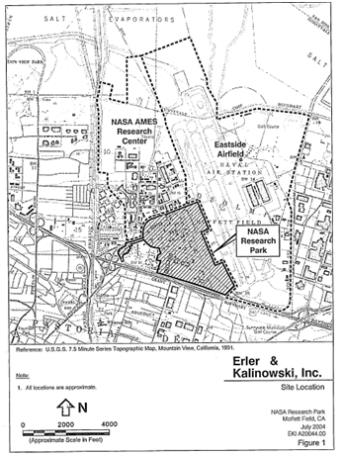
[Image FIGURE 2]
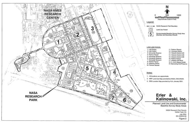
[Image FIGURE 3]
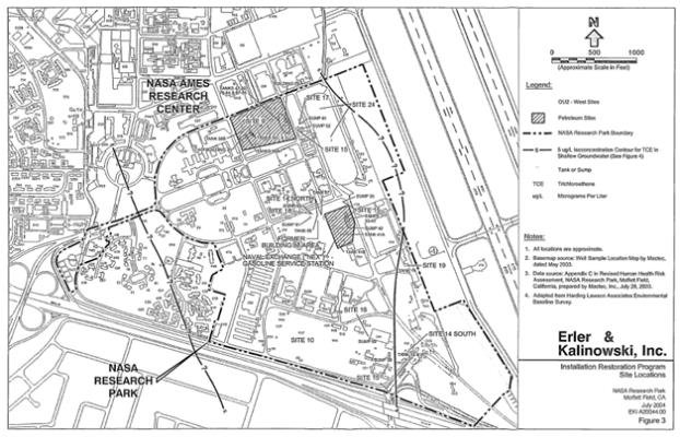
[Image FIGURE 4]
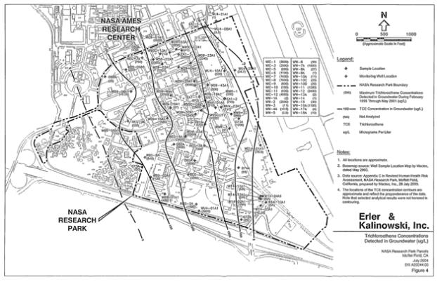
[Image FIGURE 5]
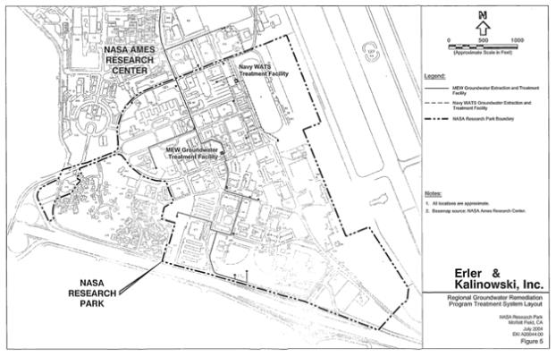
[Image FIGURE 6]
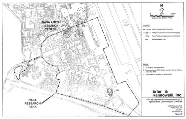
[Image FIGURE 7]
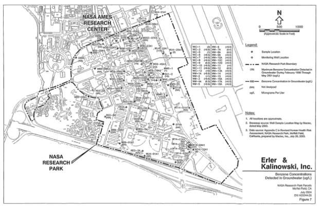
[Image FIGURE 8]
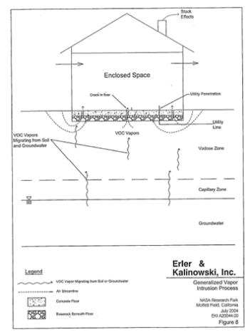
[Image FIGURE 9]
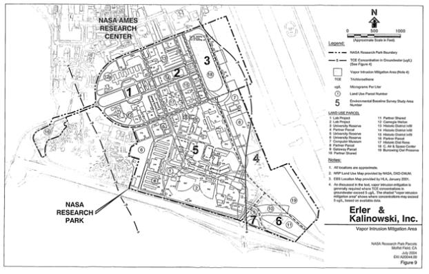
[Image FIGURE 10]
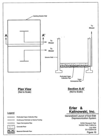
[Image FIGURE 11]
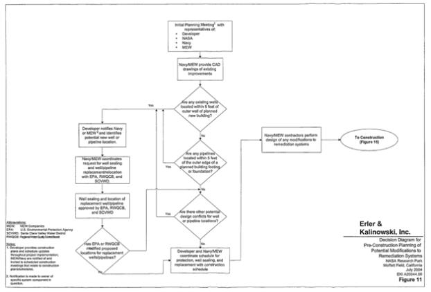
[Image FIGURE 12]
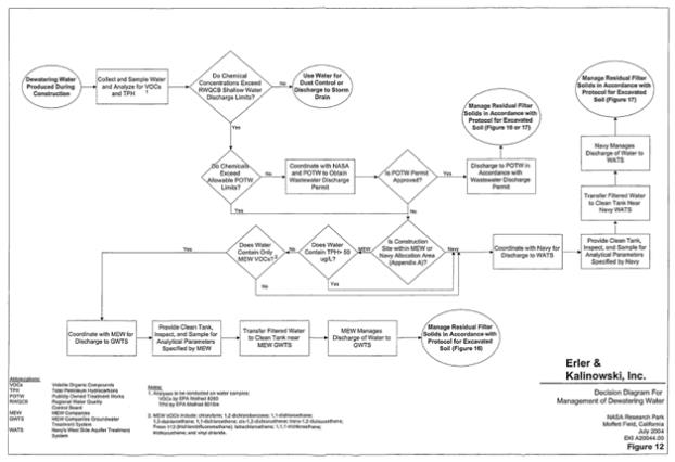
[Image FIGURE 13]
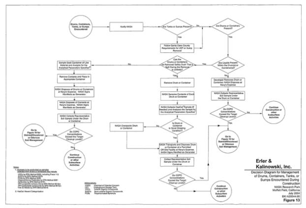
[Image FIGURE 14]
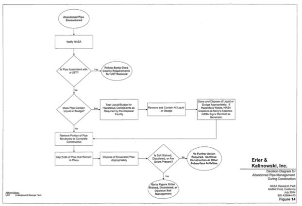
[Image FIGURE 15]
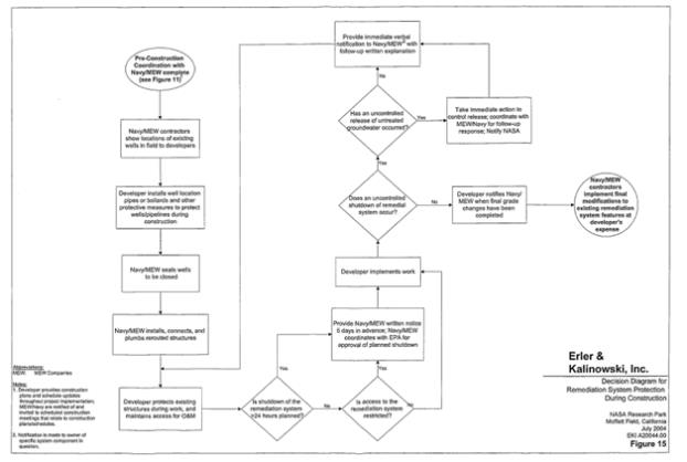
[Image FIGURE 16]
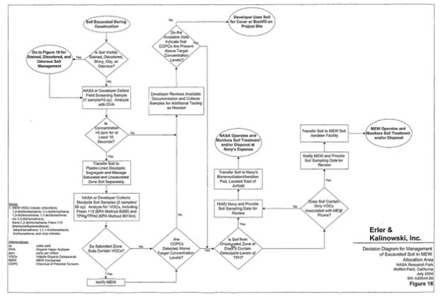
[Image FIGURE 17]
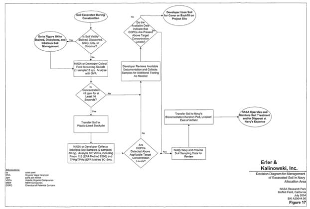
[Image FIGURE 18]
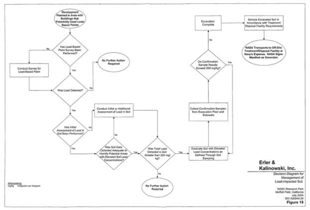
[Image FIGURE 19]
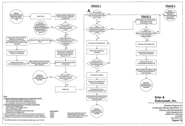
APPENDIX A
MEW Companies/Navy/NASA
Allocation Area Map
[Image EXHIBIT B1]
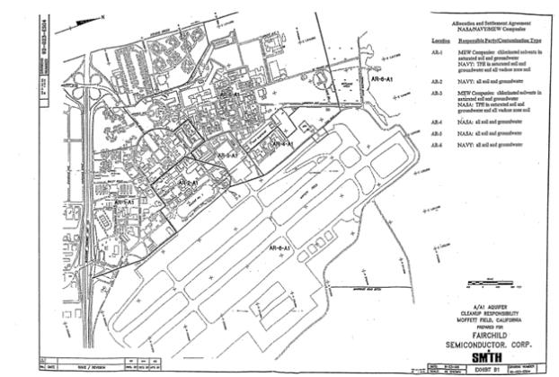
APPENDIX B
Mitigated Alternative 5 Land Use Plan from
Final Programmatic Environmental Impact Statement
Figure 2.6 from Design, Community, and Environment, NASA Xxxx Development Plan, Final Programmatic Environmental Impact Statemen5, NASA Xxxx Research Center, July 2002
[Image FIGURE 2.6]
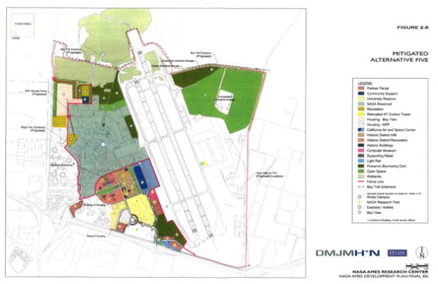
APPENDIX C
Selected Plates from
the Revised Human
Mactec, Inc., Revised Human Health Risk Assessment, NASA Research Park, Xxxxxxx Field, California, 28 July 2003
Includes:
| $ | Plate 8: Indoor Worker RME Risk; |
| $ | Plate 10: Indoor Worker RME HI; |
| $ | Plate 16: Child Resident (10 yr) RME Risk; |
| $ | Plate 18: Child Resident (10 yr) RME HI; |
| $ | Plate 20: Resident (30 yr) RJE Risk; |
| $ | Plate 22: Resident, Child (6 yr) HI, |
[Image PLATE 8]
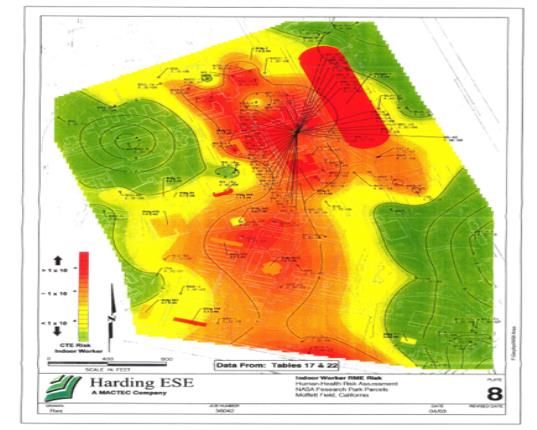
[Image PLATE 10]
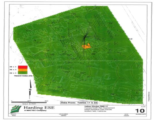
[Image PLATE 16]
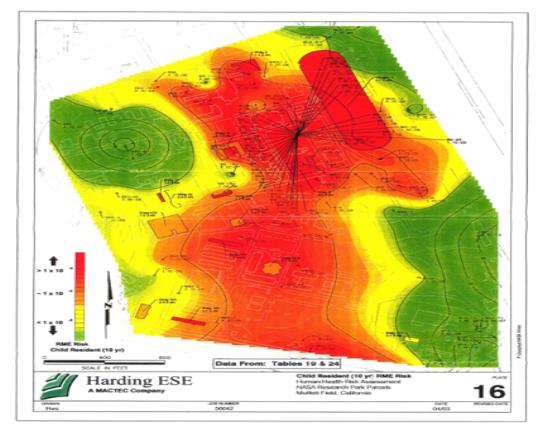
[Image PLATE 18]
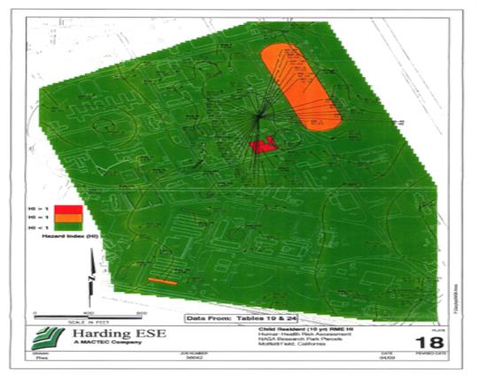
[Image PLATE 20]
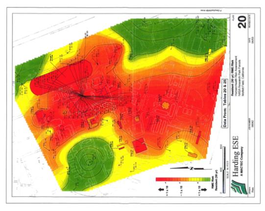
APPENDIX D
Agreement for Coordination of Construction
and MEW Remedial System Modification Work
NASA Research Park, Xxxxxxx Federal Airfield
AGREEMENT FOR COORDINATION OF CONSTRUCTION
AND MEW REMEDIAL SYSTEM MODIFICATION WORK AT
NASA RESEARCH PARK, XXXX RESEARCH CENTER, XXXXXXX FIELD,
CALIFORNIA
The National Aeronautics and Space Administration (“NASA”) enters into this Agreement for Coordination of Construction and MEW Remedial System Modification Work at NASA Research Park, Xxxx Research Center, Xxxxxxx Field, California (“Agreement”) with Xxxxxxxxx Semiconductor Corporation, a Delaware corporation, and Raytheon Company, a Delaware corporation (collectively, the “MEW Companies”), and CM SPE, LLC, a Pennsylvania limited liability company (“Project Developer”). NASA enters into this Agreement pursuant to the authority of the National Aeronautics and Space Act of 1958, as amended, 42 U.S.C. §§ 2451 et seq.
RECITALS
A. On June 9, 1989, the United States Environmental Protection Agency (“EPA”) issued a Record of Decision (the “MEW ROD”) for the Middlefield-Xxxxx-Xxxxxxx area of Mountain View, California. The MEW ROD was modified in September 1990 and April 1996 by EPA’s Explanations of Significant Differences. The MEW ROD requires the implementation of an EPA-approved regional groundwater remediation program (“RGRP”).
B. On November 29, 1990, pursuant to Section 106(a) of the Comprehensive Environmental Response, Compensation, and Liability Act of 1980, as amended by the Superfund Amendments and Reauthorization Act of 1986 (as so amended, “CERCLA”) (42 U.S.C. § 9606(a)), the EPA issued an Administrative Order for Remedial Design and Remedial Action for the MEW Site to Xxxxxxxxx Semiconductor Corporation, Schlumberger Technology Corporation, National Semiconductor Corporation, NEC Electronics, Inc., Siltec Corporation, Sobrato Development Companies, General Instrument Corporation, Tracor X-Ray, Inc., and Union Carbide Chemicals and Plastics Company Inc. (the “106 Order”).
C. On May 9, 1991, pursuant to CERCLA, the EPA entered into a Consent Decree with Intel Corporation and Raytheon Company to compel them to perform remedial actions at the MEW Site.
D. As part of the RGRP, the MEW Companies have installed, operate, monitor and maintain a groundwater monitoring and remedial system (“Remedial System”) on Xxxxxxx Field (“Xxxxxxx”) under the direction of EPA. The Remedial System’s components include, but are not limited to, groundwater monitoring xxxxx, groundwater extraction xxxxx, single and double-contained pipelines, air relief structures, electrical power and instrumentation conduits, fiber-optic instrument systems, electrical field control panels, leak detection systems, radio frequency communication links, settlement pin monuments and a groundwater treatment system (“GWTS”). The MEW Companies are required by EPA to operate the Remedial System GWTS and related
Page 1 of 13
extraction xxxxx and components continuously except during maintenance. Approval for any shutdown of more than 24 hours duration must be obtained from the EPA Remedial Project Manager (“RPM”) in advance.
E. NASA has entered into an agreement with the Project Developer to undertake redevelopment activities at Xxxxxxx in connection with the Project Developer’s lease of certain improvements at Xxxxxxx. These activities include, but are not limited to, demolition, grading, trenching and other excavation work, and construction connected with the development of office, educational, and research and development facilities (collectively, “Project Development”).
F. NASA, the MEW Companies and the Project Developer enter into this Agreement to minimize any impact of Project Development on the operation, monitoring, maintenance and modification of the Remedial System and to allow MEW Companies and the EPA access to the Remedial System during and after Project Development; and to delineate the roles and responsibilities for managing contaminated soil and groundwater that is excavated during the Project Development. NASA, the MEW Companies and the Project Developer recognize that, to coordinate Project Development and the continued operation of the Remedial System effectively, it will be necessary for NASA, the Project Developer and the MEW Companies to be in regular, frequent communication.
G. The Parties to this Agreement all agree that all actions to be taken hereunder shall be in compliance with all applicable laws and, to the extent required by law, will receive the approval of all state and federal agencies having jurisdiction over ) such actions.
NOW, THEREFORE, NASA, Project Developer and the MEW Companies agree as follows:
AGREEMENT
| 1. | Geographic Scope of Agreement |
This Agreement applies only within those geographical parts of Xxxxxxx that are or will be physically affected by the construction work performed by the Project Developer in connection with the Project Development and located within the areas designated as AR-1 and AR-3 on the attached Figure 1, together with other areas that may be affected by extensions of portions of the Remedial System that extend from AR-1 and/or AR-3.
| 2. | Scheduling of Work |
The Project Developer shall meet with the MEW Companies as early as possible during Project Development planning to coordinate Project Development with the operation, monitoring, maintenance and modification of the Remedial System. Detailed drawings showing the locations of the Remedial System components shall be provided by the MEW Companies to the Project Developer in CAD form so they can be integrated into the Project Developer’s plans.·
Page 2 of 13
| 3. | Remedial System Protection and Modification; Exacerbation of Contamination |
During Project Development, (i) the Project Developer shall protect the integrity of all components of the Remedial System and shall take all reasonable measures to minimize Remedial System downtime, in each case to the extent the Remedial System may be affected as a result of the Project Development, and (ii) the MEW Companies shall operate the Remedial System in a manner that, to the extent reasonably possible and subject to the express requirements of this Agreement, minimizes interference with the ongoing Project Development. After completion of Project Development, the MEW Companies both (a) shall protect the integrity of all components of facilities resulting from the Project Development and (b) shall take all reasonable measures to minimize interference with the Project Developer’s use of its facilities, in each case to the extent they may be affected as a result of the operation of the Remedial System, provided that the MEW Companies shall not be required to relocate components of the Remedial System as they exist on the date of this Agreement. The Project Developer shall pay any costs of relocation, replacement, alteration, protection, modification, or repair of the Remedial System caused by Project Development, to the extent any such relocation, replacement, alteration, protection, modification or repair is required by applicable laws and/or is required for the Remedial System to operate in substantially the same manner it operated prior to any such relocation, replacement, alteration, protection, modification or repair caused or necessitated by the Project Development. In addition, if the Project Developer damages any Remedial System component in a manner that causes a release of untreated groundwater or soil or if the Project Developer exacerbates existing soil or groundwater contamination, the Project Developer shall pay all costs of investigation, remediation, EPA oversight, and any penalties associated with such release or exacerbation. The design and construction of any modification to the Remedial System shall be performed by the MEW Companies; all modification costs, including EPA oversight costs, shall be paid by the Project Developer, subject to Section 18.
| 4. | Well Protection |
The Project Developer shall repair any damage to Remedial System xxxxx caused by Project Development. Prior to the initial Project Development demolition or construction field work, the MEW Companies shall field locate all Remedial System xxxxx. Prior to the start of Project Development field work, the Project Developer shall install brightly painted steel pipes over each Remedial System monitoring and extraction well designated by the MEW Companies. The painted pipe shall extend above ground not less than four feet, so as to be highly visible, and shall be buried sufficiently below the ground surface to protect the wellhead. Alternative equivalent well protection measures may be used by the Project Developer provided the MEW Companies approve any alternative protective measure in writing prior to its use.
Additionally, all Project Development work within two (2) feet of Remedial System xxxxx shall be performed manually with hand tools. Fine grading work performed in areas more than two feet from the Remedial System xxxxx but within close proximity shall be performed by light grading equipment.
Page 3 of 13
| 5. | Well Sealing and Well Replacement |
If the Project Developer determines that a Remedial System well conflicts pay all costs of well sealing and replacement and all related MEW Companies’ costs, with the planned Project Development and must be removed, the Project Developer shall including but not limited to the cost of installing replacement conduit, piping, boxes, controls and all other components needed to return a well to service, developing the well, conducting a baseline first round of groundwater sampling, and preparing all required plans, surveys and reports. The Project Developer shall be responsible for sealing all xxxxx located within 15 feet of the outer wall of a new building. No well shall be sealed or relocated without the prior written approval of the EPA RPM. Well sealing and installation shall comply with Santa Xxxxx Valley Water District (“SCVWD”) guidance and take place under SCVWD permit. Coordination with EPA and well sealing and replacement shall be performed by the MEW Companies, at the Project Developer’s sole cost, subject to Section 18.
| 6. | Remedial System Pipeline Protection and Replacement |
Prior to initial Project Development field work, the Project Developer shall provide and place steel plate or equivalent protective measures over the existing MEW Companies’ pipelines and power and control conduits. If the Project Developer determines that a pipeline conflicts with the planned Project Development and must be removed and relocated, the Project Developer shall pay all costs related to pipeline removal and replacement, including but not limited to design, permitting, review, inspection, construction and independent quality assurance inspection costs. The Project Developer shall be responsible for removing and relocating all pipelines located within five feet of the outer edge of the footing or foundation of a new building. No pipeline shall be relocated without the prior approval of the EPA RPM. Replacement pipeline installation procedures shall also be approved by the EPA RPM. Coordination to obtain EPA approval, and pipeline removal and replacement work, shall be performed by the MEW Companies at the Project Developer’s cost, subject to Section 18.
| 7. | Notification of Shutdown of Groundwater Extraction Xxxxx or GWTS |
If, during Project Development, the Project Developer believes it to be necessary that either a Remedial System extraction well or the GWTS be shut down, the Project Developer shall make written request of same to the MEW Companies no later than five (5) working days in advance of the proposed shutdown. If such shutdown does not require EPA approval, the MEW Companies shall, within five (5) working days of receipt of the Project Developer’s written request, notify Project Developer in writing either that (a) the MEW Companies consent to such request, including information on the anticipated timing of the shutdown or (b) the MEW Companies do not consent to such request and the reason(s) for such refusal. If such shutdown does require EPA approval, the MEW Companies shall, promptly upon receipt of the Project Developer’s written
Page 4 of 13
request, make appropriate application to EPA for its consent and shall notify the Project Developer of EPA’s response within one (1) working day of its receipt of EPA’s response or, failing a response from EPA within fifteen (15) working days, shall notify the Project Developer of EPA’s lack of response and any additional steps the MEW Companies have taken to elicit a response. In the event of an inadvertent shutdown of any component of the Remedial System, the Project Developer shall give immediate verbal notice to the MEW Companies, and the MEW Companies shall be responsible for any required notice to EPA pursuant to the 106 Order. Additionally, the Project Developer shall provide to the MEW Companies a written explanation of the reason for and the duration of any inadvertent shutdown within 48 hours of the shutdown.
| 8. | Access to Xxxxx and the GWTS |
Project Development shall be performed in such a way that all Remedial System xxxxx, pull boxes and the GWTS and associated components remain accessible to the EPA and the MEW Companies and their equipment for sampling, operation, maintenance, removal and replacement of pumps, and well sealing to the maximum extent practicable during and after Project Development. If it becomes necessary to restrict access to a well or other Remedial System component during Project Development, the Project Developer shall provide written notice to the MEW Companies five working days in advance of creating the restriction, with an explanation of the reason for and the expected duration of the proposed restricted access. Prior to the initial Project Development field work, the MEW Companies shall provide the Project Developer with the schedule for well sampling.
| 9. | Modifications to Well Vaults and Wellheads |
Following completion of final grade by the Project Developer, the MEW Companies shall modify the MEW xxxxx, well vaults, and pull boxes as needed based on the final grade established by the Project Developer. All costs associated with these modifications shall be paid by the Project Developer, subject to Section 18.
| 10. | Communications |
The Project Developer, all of its contractors, the MEW Companies, all of their contractors, and NASA shall each designate in writing a primary and alternate contact person, including all applicable mailing addresses, telephone numbers, email addresses and facsimile numbers. The MEW Companies shall have sole authority and responsibility for all communications with EPA regarding the Remedial System, including its operating status, any Project Development-related shutdowns and any modifications. The Project Developer shall provide the MEW Companies with all demolition, grading and construction work schedules, a full set of civil, landscaping, foundation and utility plans and specifications, and updates to these plans and specifications and schedules promptly as they occur. The MEW Companies and their contractor shall be notified of and invited to weekly construction meetings that pertain to these plans and schedules.
Page 5 of 13
| 11. | Monitoring and Sampling of Excavated Soil |
The Project Developer or NASA shall monitor all excavated soil to determine if the soils contain volatile organic compounds (“VOCs”) or petroleum constituents. Vadose zone soils shall be stockpiled and managed separately from saturated zone soils. The Project Developer shall remove and segregate concrete, asphalt, wood, piping and other demolition debris from soil and shall manage and dispose of demolition debris in accordance with all applicable regulations. The Project Developer shall pay all costs related to demolition debris disposal.
NASA, at the Project Developer’s expense and in compliance with applicable laws, shall monitor and sample soils generated from trenching and other excavation work throughout trenching and excavation activities. The soil being removed shall be visually observed for evidence of discoloration or staining. Soil exhibiting these characteristics shall be analyzed using an organic vapor analyzer (“OVA”) or equivalent device before stockpiling. Excavated soil shall be field-screened using an OVA (or equivalent) to determine if the excavated soils are clean or may be chemically affected. Field screening shall be performed in a manner acceptable to EPA, which the Project Developer, NASA and the MEW Companies currently expect will be performed with an OVA (or equivalent) at a rate of one soil sample for every 15 cubic yards of excavated soil. Excavated soils that show a continuous reading of five parts per million (“ppm”) or greater for at least ten seconds using the OVA (or equivalent) shall be considered as possibly containing chemicals, and shall be segregated. NASA shall transfer soil exhibiting these characteristics to a plastic-lined stockpile area in or near the area of trenching or excavation. Soil samples shall be collected from random locations within the stockpile at a rate of two samples for every 50 cubic yards of stockpiled soil. Each of the two samples shall consist of at least five composite samples representative of the stockpiled soil. The samples shall be submitted to a state-certified laboratory and analyzed using EPA Method 8260 (or its superceding EPA Method), including cis-1, 2-dichloroethene and Freon 113 and EPA Method 8015 (or its superceding EPA Method) for high and low boiling point total petroleum hydrocarbons (“TPH”). After the soil has been verified to conform to the soil cleanup standards specified in the MEW ROD, the soils may be used for on-site cover or backfill. Clean soil that is tested using the field head space method with an OVA (or equivalent) that does not have a reading greater than five ppm for at least ten seconds also may be used for on-site cover or backfill. Soil that does not qualify as clean soil shall be managed in accordance with Sections 13.2 through 13.6 of this Agreement.
| 11.1 | Excavated Soil Classification and Monitoring Procedure |
The Project Developer or NASA shall monitor excavated soil with an OVA (or equivalent) to determine if the soils are clean or may contain chemicals, as defined below:
Clean Soil: Soil that does not have a reading greater than five ppm continuously for ten seconds using the field head space method with an OVA (or equivalent) specified below will be considered clean soil.
Page 6 of 13
Soil Containing Chemicals: Soil that does not meet the definition of clean soil will be considered soil containing chemicals.
| 11.2 | Field Head Space Methods: |
(a) A soil sample shall be taken from excavated soil in the backhoe bucket at a point out of the excavation.
(b) The soil to be tested shall be placed into an unused re-sealable plastic bag or clean xxxxx jar container with a minimum volume of one quart or one liter, until the container is half full.
(c) The container shall be sealed and left to sit under direct sunlight for approximately five minutes.
(d) The container shall be opened just enough to allow the probe of the OVA (or equivalent) to be inserted into the container’s headspace.
(e) Any sample having a reading of five ppm or greater continuously for at least ten seconds shall be considered soil containing chemicals.
| 12. | Notification of Saturated Soil Containing VOC |
If VOCs are determined to exist in saturated zone soils, the Project Developer shall immediately notify the MEW Companies’ representative.
| 13. | Management and Disposition of Soils |
| 13.1 | Clean Soil |
NASA shall be responsible for the determination as to whether soil qualifies as clean soil either because it has been classified as clean soil in accordance with Section 11.1 of this Agreement or has been treated to the soil cleanup standards specified in the MEW ROD. Clean soil that does not require treatment may be reused for cover or backfill or shall be transported to the open field north of Electrical Substation West (N225A) on Xxxxxxx, shown as Area A on the attached Figure 2, or to other areas on Xxxxxxx designated by NASA, and spread by the Project Developer at the Project Developer’s cost. NASA and the Project Developer agree that the MEW Companies shall not be responsible for (a) .any determination made by NASA or the Project Developer that any soil qualifies as clean soil or that any soil may be used for any particular purpose at any particular location on Xxxxxxx, or (b) any other actions or omissions by NASA or the Project Developer with respect to their respective handling of soils pursuant to this Agreement.
| 13.2 | Vadose Zone Soils and Saturated Soils Containing TPH |
Vadose zone and saturated soils containing TPH from AR-1 (whether or not they also contain VOCs) shall be transported by the Project Developer to the
Page 7 of 13
bioremediation pad on the east side of Xxxxxxx, as shown on Figure 3, or to other areas on Xxxxxxx designated by NASA, and shall be managed by NASA in accordance with the procedures specified in the document entitled “Coordination of Construction and Navy Remedial System Modification Work.”
Vadose zone and saturated soils containing TPH from AR-3 (whether or not they also contain VOCs) shall be transported by the Project Developer to the bioremediation pad at the northwest xxxxx of Xxxxxxx, shown as Area C on Figure 2, or to other areas on Xxxxxxx designated by NASA, and shall be managed by NASA.
| 13.3 | Saturated Zone Soils Containing Only VOCs |
The Project Developer shall notify the MEW Companies promptly if any saturated zone soil in AR-1 or AR-3 is determined by analytical testing to contain only those VOCs associated with the MEW plume at concentrations exceeding MEW ROD soil cleanup standards. The MEW Companies shall manage and dispose of these soils at their cost. The Project Developer or NASA shall promptly make available to the MEW Companies copies of analytical soil data. Following review of the data, any soils that are found to be the responsibility of the MEW Companies shall be delivered by the Project Developer to a soil aeration facility on Xxxxxxx at the location shown as Area B on Figure 2 (the “MEW Soil Aeration Facility”) and treated and/or disposed of by the MEW Companies. Treatment or offsite disposal of the soil ,shall be at the discretion and timing of the MEW Companies, in accordance with CERCLA Section 121(d). If treated, the soils shall be treated to the soil cleanup standards specified in the MEW ROD. The Project Developer shall pay all costs of excavating and delivering the soil to the MEW Soil Aeration Facility. The MEW Companies shall pay all costs of treating the soil and spreading the treated soil on-site or disposing of it offsite. If the MEW Companies elect to dispose of soil offsite, the MEW Companies shall select the offsite disposal site in accordance with CERCLA Section 121(d), subject to NASA’s approval, which shall not be withheld unreasonably, and NASA shall be designated the generator and sign all necessary waste manifests.
| 13.4 | Polyethylene Liners |
The Project Developer shall provide plastic liners and covers for the soil stockpiles located in the areas of trenching and excavation. The MEW Companies shall provide liners and covers for the soil at the MEW Soil Aeration Facility. The location of the soil stockpiles in the areas of trenching and excavation shall be designated by NASA.
| 13.5 | MEW Soil Aeration Facility Sampling and Testing Procedures |
Following aeration of soils treated by the MEW Companies pursuant to Section 13.3, the MEW Companies shall collect two discrete soil samples for every 50 cubic yards of treated soil. Each of the two samples shall consist of at least five composite samples representative of the treated soil. The samples shall be analyzed using EPA Method 8260 (or its superceding EPA Method), including cis-1,2-dichloroethene and Freon.
Page 8 of 13
| 13.6 | On-Site Reuse |
After soil aerated by the MEW Companies has been determined to meet soil cleanup standards, the MEW Companies shall move the clean soil onto the open field adjacent to the MEW Soil Aeration Facility and spread it in a manner that effectively separates the clean soil from any soil remaining at or brought to the MEW Soil Aeration Facility for treatment.
| 13.7 | Soil Management |
All soil management plans (including, without limitation, those for screening, testing, treating and disposing of soils) shall be performed in accordance with EPA-approved plans to the extent required by the 106 Order.
| 14. | Management and Discharge of Groundwater Generated During Excavation and Dewatering Activities |
The Project Developer may be required to xxxxxxx pipeline trenches and other excavations and convey water away from excavations. Groundwater in the area of Project Development may contain VOCs or TPH. The Project Developer shall manage, contain and discharge all water removed from excavation areas. The Project Developer shall transport the water to above ground tanks, test the water by EPA Method 8260 and EPA Method 8015 (or their superceding EPA Methods) and discharge the water as follows:
| 14.1 | Ground Water Containing TPH |
If the groundwater from AR-1 contains TPH above 50 parts per billion (“ppb”) (or such lower standard as may in the future be established by EPA), as determined by EPA Method 8015 (or its superceding EPA Method), it shall not be discharged to the Remedial System GWTS. The Project Developer shall obtain all necessary approvals for discharge of such groundwater at alternate sites. (Depending on the chemical concentrations, the Project Developer may be able to obtain permission from the City of Sunnyvale Waste Water Treatment Plant or the City of Palo Alto Waste Water Treatment Plant to discharge the water to the NASA sanitary sewer systems.) The water shall be filtered before any discharge to the sewer system and the solids stored and subsequently managed by the Navy in accordance with the document entitled “Coordination·of Construction and Navy Remedial System Modification Work.”
If the groundwater from AR-1 contains TPH above 50 ppb, and cannot be discharged to the sanitary sewer, the Project Developer shall deliver it to the Navy’s Westside Aquifer Treatment System on Xxxxxxx for treatment by the Navy.
If the groundwater from AR-3 contains TPH above 50 ppb, as determined by EPA Method 8015 (or its superceding EPA Method), it shall not be discharged to the Remedial System GWTS. The Project Developer shall obtain all necessary approvals for discharge of such groundwater at alternate sites. (Depending on the chemical concentrations, the Project Developer may be able to obtain permission from the City of
Page 9 of 13
Sunnyvale Waste Water Treatment Plant or the City of Palo Alto Waste Water Treatment Plant to discharge the water to the NASA sanitary sewer systems.) The water shall be filtered before any discharge to the sewer system and the solids stored and subsequently managed by the Navy in accordance with the document entitled “Coordination of Construction and Navy Remedial System Modification Work.”
If the groundwater from AR-3 contains TPH above 50 ppb, and cannot be discharged to the sanitary sewer, the Project Developer shall deliver it to NASA’s RGRP Treatment System on Xxxxxxx for treatment by NASA.
| 14.2 | Groundwater Containing VOCs |
If the groundwater from AR-I or AR-3 contains TPH below 50 ppb (or such lower standard as may in the future be established by EPA) and contains VOCs that are identified as those associated with the MEW plume, the groundwater can be discharged, if acceptable to EPA (to the extent EPA approval is required by the 106 Order), to the Remedial System GWTS. If EPA approves (if such approval is so required), then the Project Developer shall deliver the groundwater to clean Xxxxx or similar tanks adjacent to the Remedial System GWTS at the location shown as the MEW Xxxxx Tank Staging Area on Figure 4. The Project Developer shall inspect and sample the storage tanks before using them to insure that they are clean. Sample results shall be provided to the MEW Companies, and the MEW Companies shall have an opportunity to inspect the tanks before their use. Treatment and discharge of groundwater through the Remedial System GWTS shall be performed by the MEW Companies. All groundwater shall be filtered before it is pumped into the clean storage tanks to minimize sediment buildup in the storage tanks. All solids removed from the groundwater and any filters shall be stored and subsequently characterized, managed and disposed of in the same manner as contaminated soils as specified in Sections 11 through 13 of this Agreement. NASA shall be designated the generator and shall sign all necessary waste manifests for the solids and filter wastes. The Project Developer shall pay all costs associated with extraction, delivery and storage of groundwater prior to treatment at the GWTS. The MEW Companies shall pay all costs of pumping the groundwater from the storage tanks and treating it through the Remedial System GWTS. The MEW Companies shall treat the stored water within a reasonable timeframe.
| 15. | Contractor Compliance With This Agreement |
NASA, the MEW Companies, and the Project Developer each shall provide a copy of this Agreement to their respective contractors and subcontractors and shall ensure that compliance with this Agreement is made a material part of their respective agreements with their contractors and subcontractors.
| 16. | NASA Appropriations |
NASA agrees to use its best efforts in the performance of this Agreement. However, all NASA activities under or pursuant to this Agreement are subject to the availability of appropriated funds. No provision of this Agreement shall be interpreted
Page 10 of 13
as, or constitute, a commitment or requirement that NASA or any other Federal Agency obligate or pay funds in contravention of the Anti-Deficiency Act, 31 U.S.C. 1341. Notwithstanding the foregoing, NASA agrees that, during the period in which this Agreement remains operative, NASA will be diligent in seeking appropriation of funds for the purpose of performing NASA’s obligations set forth in this Agreement.
| 17. | Notices |
All written notices required by this Agreement shall be deemed effective (1) when delivered, if personally delivered to the person being served or (2) three business days after deposit in the mail if mailed by United States mail, postage paid certified, return receipt requested:
If To: “Project Developer”:
CM SPE, LLC
0000 Xxxxxx Xxxxxx
Pittsburgh, PA 15213
Attn: Xxxxx X. Xxxxx
Facsimile: (000) 000-0000
If To: “MEW Companies”
Xxxxxxxxx Semiconductor Corporation
Xxxxxxxx X. Xxxxxxx
Remediation Manager
Schlumberger Limited
225 Sugar Land
Drive Sugar Land, TX 77478
Facsimile: (000) 000-0000
Xxxxxxx X. Xxxxxxx, Esq.
Senior Counsel
Raytheon Corporation
000 Xxxxxx Xxxxxx
Lexington, MA 02421
Facsimile: (000) 000-0000
If To: ‘‘NASA”
Mr. Xxx Xxxxx
NASA Xxxx Research Center
MS 218-1
Xxxxxxx Field, CA 94035
Facsimile: (000) 000-0000
Page 11 of 13
| 18. | Review/Audit of MEW Costs |
With respect to any and all work to be performed by the MEW Companies hereunder at Project Developer’s cost, including, without limitation, work performed pursuant to Sections 3, 5, 6 and 9 hereof:
18.1 All such work shall be conducted only to the extent required by applicable laws and/or to enable the Remedial System to operate in substantially the manner it operated prior to any damage, modification or alteration caused or required by the Project Development, and all costs related to such work shall be commercially reasonable and subject to Project Developer’s prior approval in accordance with this Section 18, which approval shall not be unreasonably withheld or delayed;
18.2 Prior to commencing such work and incurring such costs, the MEW Companies shall provide to Project Developer a detailed description of such work and cost estimates and such back-up documentation as Project Developer may reasonably request, and Project Developer shall be given an opportunity to recommend revisions or modifications to such scope of work and cost estimates. Project Developer shall either approve or disapprove (with reasonable detail as to grounds for disapproval) such work scope and cost estimate within thirty (30) days after receipt of same, unless sooner approval or disapproval is required for emergency repairs, in which case Project Developer shall respond as promptly as reasonable practicable;
18.3 After completing such work and incurring such costs, the MEW Companies shall provide to Project Developer paid invoices and such other evidence of payment of such costs previously approved by Project Developer as Project Developer may reasonably request; and
18.4 Project Developer shall have a period of thirty (30) days after submission of such proof of payment to review such costs and the work performed and, at Project Developer’s sole option and expense, to complete an audit of the MEW Companies’ records with respect to such costs and work performed. If, as a result of such review and/or audit, Project Developer determines that any such work and/or costs are outside the scope of Project Developer’s responsibility hereunder and/or were not approved by Project Developer as required hereunder, then Project Developer shall so notify the MEW Companies and the parties shall attempt to resolve such dispute extrajudicially. If the Project Developer and MEW Companies are unable to resolve such dispute extrajudicially, then either party may pursue any available remedy pursuant to applicable law or, by mutual agreement, may submit the dispute to such alternative dispute resolution procedure as may be mutually acceptable.
| 19. | Effective Date |
This Agreement shall take effect on January 8, 2003.
Page 12 of 13
IN WITNESS THEREOF, the following parties have entered into this Agreement.
| NATIONAL AERONAUTICS AND SPACE ADMINISTRATION | ||||||||
| By: |
|
Dated: |
| |||||
| X. Xxxxx Xxxxxxx | ||||||||
| Title: | Director, Xxxx Research Center | |||||||
| CM SPE, LLC | ||||||||
| By: |
|
Dated: |
| |||||
| Xxxxx Xxxxx | ||||||||
| Title: | President and CEO | |||||||
| RAYTHEON COMPANY | ||||||||
| By: |
|
Dated: |
| |||||
| Title: | ||||||||
| XXXXXXXXX SEMICONDUCTOR CORPORATION | ||||||||
| By: |
|
Dated: |
| |||||
| Title: |
|
|||||||
Page 13 of 13
EXHIBIT O
REQUIREMENTS AND PROCEDURES FOR COORDINATION OF CONSTRUCTION AND NAVY RE: MEDIAL SYSTEM MODIFICATION WORK AT NASA RESEARCH PARK, XXXX RESEARCH CENTER, XXXXXXX FIELD, CALIFORNIA
The National Aeronautics and Space Administration (‘‘NASA”) will enter into a certain Agreement for Coordination of Construction and Navy Remedial System Modification Work at the proposed NASA Research Park (‘‘NRP”), Xxxx Research Center, Xxxxxxx Field, California (“Agreement”) with the United States Navy. The following recitals, requirements and procedures are taken from the proposed Agreement and will be followed by NASA, the Navy and CM SPE, LLC (“CM SPE”) in regard to the activities under Article 26 of the Lease.
RECITALS
A. On June 9, 1989, the U1:1ited States Environmental Protection Agency (“EPA”) issued a Record of Decision (the “MEW ROD”) for the Middlefield-Xxxxx-Xxxxxxx area of Mountain View, California. The MEW ROD was modified in September 1990 and April 1996 by EPA’s Explanations of Significant Differences. The MEW ROD requires the implementation of an EPA-approved regional groundwater remediation program (“RGRP”).
B. In September, 1990, a Federal Facility Agreement (“FFA”) under CERCLA Section 120 was signed by the EPA, the Navy, and the State of California, represented by the California Department of Health Services (“DHS”), and the California Regional Water Quality Control Board (“RWQCB”). The FFA states the Navy’s responsibilities for the investigation and remediation of contaminated soil and groundwater within the proposed NRP area.
C. On December 22, 1992, the Navy and NASA signed a Memorandum of Understanding (“MOU”) that stated the Navy would continue to be responsible for the investigation and remediation of its environmental contamination after the transfer of the
1
former Naval Air Station Xxxxxxx Field to NASA. In addition to the groundwater contamination, the MOU includes Navy responsibility for petroleum contamination in the soil and groundwater, and for lead in the soil caused by lead based paint on the buildings. This MOU was further clarified by the Navy in a letter signed on October 4, 1993, which stated that “The Navy’s obligations under the MOU shall include taking possession of, and properly managing any contaminated soil or groundwater that has been left in place in accordance with a CERCLA, RCRA, or other cleanup remedy but subsequently upon its excavation, disturbance, or discharge by NASA during development for reuse of Xxxxxxx Field becomes hazardous waste, or requires treatment prior to discharge.”
D. On December 17, 1993, EPA signed the Xxxxxxx Field FFA amendment, which had already been signed by the Navy, the California Department of Toxic Substance Control (“DTSC”) and the RWQCB. In this FFA amendment, the Navy adopted the MEW ROD for the remediation of soil and groundwater contaminated with chlorinated solvents within the proposed NRP area.
E. By 1998, the Navy, NASA, and the MEW Companies had agreed in principle to an allocation and settlement of each party’s responsibilities for the RGRP. NASA and the MEW Companies signed this Allocation and Settlement Agreement on March 16, 1998.
F. As part of the RGRP, the MEW Companies have installed, operate, monitor and maintain a groundwater monitoring and remedial system on Xxxxxxx Field (“Xxxxxxx”) under the direction of EPA. These components include, but are not limited to, groundwater monitoring xxxxx, groundwater extraction xxxxx, single and double-contained pipelines, air relief structures, electrical power and instrumentation conduits, fiber-optic instrument systems, electrical field control panels, leak detection systems, radio frequency communication links, settlement pin monuments and a groundwater treatment system (“GWTS”). The MEW Companies are required by EPA to operate the GWTS and related extraction xxxxx and components continuously except during maintenance. Approval for any shutdown of more than 24 hours duration must be obtained from the EPA Remedial Project Manager (“RPM”) in advance.
2
G. Pursuant to its FFA, the Navy has installed, operates, monitors and maintains a groundwater monitoring and remedial system, the Westside Aquifer Treatment System (“WATS”) on Xxxxxxx under the direction of EPA and the RWQCB. The WATS’ components include, but are not limited to, groundwater monitoring xxxxx, groundwater extraction xxxxx, pipelines, air relief structures, electrical power and instrumentation conduits, fiber-optic instrument systems, electrical field control panels, leak detection systems, settlement pin monuments and a groundwater treatment system. The Navy is required by EPA to operate the WATS and related extraction xxxxx and components continuously except during maintenance. Approval for any shutdown of more than 24 hours duration must be obtained from the EPA RPM in advance.
H. The Navy is also responsible for investigation and remediation of petroleum sites at Xxxxxxx, with oversight by the RWQCB. The Navy had installed a treatment system at Site 14 South to address petroleum contamination. The Navy had also installed an Iron Curtain demonstration project west of Hangar 1.
I. NASA plans to sign separate agreements with the MEW Companies and each “Project Developer” (including CM SPE) to undertake redevelopment activities at Xxxxxxx in connection with the Project Developers’ leases of certain improvements at Xxxxxxx. These activities include, but are not limited to, demolition, grading, trenching and other excavation work, and construction connected with the development of office, educational, and research and development facilities (collectively, “Project Development”).
J. NASA and the Navy will enter into the Agreement to minimize any impact of Project Development on the operation, monitoring, maintenance and modification of the WATS and to allow Navy access to the WATS during and after Project Development; and to clarify the roles and responsibilities for managing contaminated soil and groundwater that is excavated during the Project Development. NASA and the Navy recognize that, to coordinate Project Development and the continued operation of the WATS effectively, it will be necessary for NASA and the Navy to be in regular, frequent communication.
3
REQUIREMENTS AND PROCEDURES
FOR NASA, THE NAVY AND CM SPE
| 1. | Geographic Scope of Agreement |
These Requirements and Procedures apply only within those geographical parts of Xxxxxxx designated as AR-1, AR-2, and AR-6 on the attached Figure 1.
| 2. | Scheduling of Work |
NASA shall meet with the Navy as early as possible during Project Development planning to coordinate Project Development with the operation, monitoring, maintenance and modification of the WATS and any petroleum site or other remedial work (collectively, the “Remedial System”). Detailed drawings showing the locations of the WATS and any other treatment system components shall be provided by the Navy to NASA in CAD form so they can be integrated into the Project Developer’s plans.
| 3. | Remedial System Protection and Modification; Exacerbation of Contamination |
The Project Developer shall protect the integrity of all components of the Remedial System during Project Development and shall take all reasonable measures to minimize Remedial System downtime. The Project Developer shall pay any costs of relocation, replacement, alteration, protection, modification, or repair of the Remedial System caused by Project Development. In addition, if the Project Developer damages any Remedial System component in a manner that causes a release of untreated groundwater or soil or if the Project Developer exacerbates existing soil or groundwater contamination, the Project Developer shall pay all costs of investigation, remediation, EPA oversight, and any penalties associated with such release or exacerbation. The design and construction of any modification to the Remedial System shall be performed by the Navy contractors, under separate contract to the Project Developer; all modification costs, including EPA oversight costs, shall be paid by the Project Developer.
| 4. | Well Protection |
The Project Developer shall repair any damage to Remedial System xxxxx caused by Project Development. Prior to the initial Project Development demolition or construction fieldwork, the Navy shall field locate all Remedial System xxxxx. Prior to
4
the start of Project Development fieldwork, the Project Developer shall install brightly painted steel pipes over each Remedial System monitoring and extraction well designated by the Navy. The painted pipe shall extend above ground not less than four feet, so as to be highly visible, and shall be buried sufficiently below the ground surface to protect the wellhead. Alternative equivalent well protection measures may be used by the Project Developer provided the Navy approves any alternative protective measure in writing prior to its use.
Additionally, all Project Development work within two feet of Remedial System xxxxx shall be performed manually with hand tools. Fine grading work performed in areas more than two feet from the Remedial System xxxxx but within close proximity shall be performed by light grading equipment.
| 5. | Well Sealing and Well Replacement |
If the Project Developer determines that a Remedial System well conflicts with the planned Project Development and must be removed, the Project Developer shall pay all costs of well sealing and replacement and all related Navy costs, including but not limited to the cost of installing replacement conduit, piping, boxes, controls and all other components needed to return a well to service, developing the well, conducting a baseline first round of groundwater sampling, and preparing all required plans, surveys and reports. The Project Developer shall be responsible for sealing all xxxxx located within 15 feet of the outer wall of a new building. No well shall be sealed or relocated without the prior written approval of the EPA and RWQCB RPMs. Well sealing and installation shall comply with Santa Xxxxx Valley Water District (“SCVWD”) guidance and take place under SCVWD permit. Coordination with EPA and the RWQCB, and well sealing and replacement, shall be performed by the Navy’s contractor, under separate contract with the Project Developer, at the Project Developer’s sole cost.
| 6. | Remedial System Pipeline Protection and Replacement |
Prior to initial Project Development field work, the Project Developer shall provide and place steel plate or equivalent protective measures over the existing Navy pipelines and power and control conduits. If the Project Developer determines that a pipeline, or other treatment system component, conflicts with the planned Project
5
Development and must be removed and relocated, the Project Developer shall pay all costs related to pipeline, and other treatment system component, removal and replacement, including but not limited to design, permitting, review, inspection, construction and independent quality assurance inspection costs. The Project Developer shall be responsible for removing and relocating all pipelines and other components located within five feet of the outer edge of the footing or foundation of a new building. No pipeline or other component shall be relocated without the prior approval of the EPA and RWQCB RPMs. Replacement pipeline installation procedures shall also be approved by the EPA and RWQCB RPMs. Coordination to obtain the approval of EPA and the RWQCB, and pipeline removal and replacement work, shall be performed by the Navy’s contractor, under separate contract to the Project Developer, at the Project Developer’s cost.
| 7. | Notification of Shutdown of Groundwater Extraction Xxxxx or GWTS |
If it appears necessary to shut down a Remedial System extraction well or the WATS during Project Development, NASA shall give written notice to the Navy five working days in advance of the proposed shutdown. In the event of an inadvertent shutdown of any component of the Remedial System, the Project Developer shall give immediate verbal notice to the Navy. Additionally, NASA shall provide to the Navy a written explanation of the reason for and the duration of any inadvertent shutdown within 48 hours of the shutdown.
| 8. | Access to Xxxxx and the GWTS |
Project Development shall be performed in such a way that all Remedial System xxxxx, pull boxes and the WATS and associated components remain accessible to the EPA, RWQCB, and the Navy and their equipment for sampling, operation, maintenance, removal and replacement of pumps, and well sealing to the maximum extent practicable during and after Project Development. If it becomes necessary to restrict access to a well or other Remedial System component during Project Development, NASA shall provide written notice to the Navy five working days in advance of creating the restriction, with an explanation of the reason for and the expected duration of the proposed restricted access. Prior to the initial Project Development fieldwork, the Navy shall provide NASA with the schedule for well sampling.
6
| 9. | Modifications to Well Vaults and Wellheads |
Following completion of final grade by the Project Developer, the Navy’s contractor, under separate contract to the Project Developer, shall modify the Navy xxxxx, well vaults, and pull boxes as needed based on the final grade established by the Project Developer. All costs associated with these modifications shall be paid by the Project Developer.
| 10. | Communications |
The Project Developer, all of its contractors, the Navy, all of their contractors, and NASA shall each designate in writing a primary and alternate contact person, including all applicable mailing addresses, telephone numbers, email addresses and facsimile numbers. The Navy shall have sole authority and responsibility for all communications with EPA and RWQCB regarding the Remedial System, including its operating status, any Project Development-related shutdowns and any modifications. NASA shall provide the Navy with all demolition, grading and construction work schedules, a full set of civil, landscaping, foundation and utility plans and specifications, and updates to these plans and specifications and schedules promptly as they occur. The Navy and their contractor shall be notified of and invited to weekly construction meetings that pertain to these plans and schedules.
| 11. | Monitoring and Sampling of Excavated Soil |
The Project Developer shall remove soils contaminated with lead from lead-based paint around the buildings that have been identified by NASA, prior to building demolition. NASA shall properly dispose of this soil at the Navy’s expense. The Project Developer or NASA, at the Project Developer’s expense, shall monitor all excavated soil to determine if the soils contain volatile organic compounds (“VOCs”) or petroleum constituents. Vadose zone soils shall be stockpiled and managed separately from saturated zone soils. The Project Developer shall remove and segregate concrete, asphalt, wood, piping and other demolition debris from soil and shall manage and dispose of demolition debris in accordance with all applicable regulations. The Project Developer shall pay all costs related to demolition debris disposal.
7
The Project Developer or NASA, at the Project Developer’s expense, shall monitor and sample soils generated from trenching and other excavation work throughout trenching and excavation activities. The soil being removed shall be visually observed for evidence of discoloration or staining. Soil exhibiting these characteristics shall be analyzed using an organic vapor analyzer (“OVA”) or equivalent device before stockpiling. Excavated soil shall be field-screened using an OVA (or equivalent) to determine if the excavated soils are clean or may be chemically affected. Field screening with an OVA (or equivalent) shall be performed at a rate of one soil sample for every 15 cubic yards of excavated soil. Excavated soils that show a continuous reading of five parts per million (“ppm”) or greater for at least ten seconds using the OVA (or equivalent) shall be considered as possibly containing chemicals, and shall be segregated. The Project Developer shall transfer soil exhibiting these characteristics to a plastic-lined stockpile area in or near the area of trenching or excavation. Soil samples shall be collected from random locations within the stockpile at a rate of two samples for every 50 cubic yards of stockpiled soil. Each of the two samples shall consist of at least five composite samples representative of the stockpiled soil. The samples shall be submitted to a state-certified laboratory and analyzed using EPA Method 8260 (or its superceding EPA Method), including cis-1, 2-dichloroethene and Freon 113 and EPA Method 8015 (or its superceding EPA Method) for high and low boiling point total petroleum hydrocarbons (“TPH”). After the soil has been verified to conform to the soil cleanup standards specified in the MEW ROD, and the Navy petroleum site cleanup standards, the soils may be used for on-site cover or backfill. Clean soil that is tested using the field head space method with an OVA (or equivalent) that does not have a reading greater than five ppm for at least ten seconds also may be used for on-site cover or backfill. Soil that does not qualify as clean soil shall be managed in accordance with Sections 13.2 through 13.6 of this Exhibit O.
8
| 11.1 | Excavated Soil Classification and Monitoring Procedure |
The Project Developer or NASA shall monitor excavated soil with an OVA (or equivalent) to determine if the soils are clean or may contain chemicals, as defined below:
Clean Soil: Soil that does not have a reading greater than five ppm continuously for ten seconds using the field head space method with an OVA (or equivalent) specified below will be considered clean soil.
Soil Containing Chemicals: Soil that does not meet the definition of clean soil will be considered soil containing chemicals.
| 11.2 | Field Head Space Methods: |
(a) A soil sample shall be taken from excavated soil in the backhoe bucket at a point out of the excavation.
(b) The soil to be tested shall be placed into an unused re-sealable plastic bag or clean xxxxx jar container with a minimum volume of one quart or one liter, until the container is half full.
(c) The container shall be sealed and left to sit under direct sunlight for approximately five minutes.
(d) The container shall be opened just enough to allow the probe of the OVA (or equivalent) to be inserted into the container’s headspace.
(e) Any sample having a reading of five ppm or greater continuously for at least ten seconds shall be considered soil containing chemicals.
| 12. | Notification of Saturated Soil Containing VOCs or TPH |
If VOCs are determined to exist in saturated zone soils in AR-1, the Project Developer shall immediately notify the MEW Companies’ representative. If VOCs are determined to exist in saturated zone soils in AR-2 or AR-6, NASA shall immediately notify the Navy. If TPH is determined to exist in saturated zone soils in AR-1, AR-2, or AR-6, NASA shall immediately notify the Navy.
| 13. | Management and Disposition of Soils |
| 13.1 | Clean Soil |
NASA shall be solely responsible for the determination as to whether soil qualifies as clean soil either because it has been classified as clean soil in accordance with Section 11.1 of this Exhibit O or has been treated to the soil cleanup standards specified in the MEW ROD or the Navy petroleum site standards. Clean soil that does not require treatment may be reused for cover or backfill or shall be transported to the open field
9
north of Electrical Substation West (N225A) on Xxxxxxx, shown as Area A on the attached Figure 2, or to other areas on Xxxxxxx designated by NASA, and spread by the Project Developer at the Project Developer’s cost. NASA agrees that Navy shall not be responsible for any determination made by NASA or the Project Developer that any soil qualifies as clean soil or that any soil may be used for any particular purpose at any particular location on Xxxxxxx.
| 13.2 | Vadose Zone Soils and Saturated Soils Containing TPH |
Vadose zone and saturated soils containing TPH (whether or not they also contain VOCs) shall be transported by the Project Developer to the bioremediation pad on the east side of Xxxxxxx, as shown on Figure 3, or to other areas on Xxxxxxx designated by NASA, and shall be managed by NASA, at the Navy’s expense.
| 13.3 | Saturated Zone Soils Containing Only VOCs |
The Project Developer shall notify the MEW Companies promptly if any saturated zone soil in AR-1 is determined by analytical testing to contain only those VOCs associated with the MEW plume at concentrations exceeding MEW ROD soil cleanup standards. The MEW Companies shall manage and dispose of these soils as stated in the Agreement for Coordination of Construction and MEW Remedial System Modification Work (the “MEW Agreement”).
NASA shall notify the Navy promptly if any saturated zone soil in AR-2 or AR-6 is determined by analytical testing to contain VOCs at concentrations exceeding MEW ROD soil cleanup standards, or if any saturated zone soil in AR-I, AR-2, or AR-6 is determined by analytical testing to contain TPH above the Navy petroleum site cleanup standards. NASA shall manage and dispose, pursuant to CERCLA Section 121 (d), these soils at the Navy’s cost.
NASA shall promptly make available to the Navy copies of analytical soil data. Following review of the data, any soils that are found to be the responsibility of the Navy shall be delivered by the Project Developer to the bioremediation pad on the east side of Xxxxxxx, as shown on Figure 3, where it will be managed by NASA at the Navy’s expense. Treatment or offsite disposal of the soil, pursuant to CERCLA Section 121 (d) shall be at the discretion and timing of NASA. If treated, the soils shall be treated to the
10
soil cleanup standards specified in the MEW ROD or Navy’s petroleum site cleanup standards. The Project Developer shall pay all costs of excavating and delivering the soil to the East Side Bioremediation Pad. The Navy shall pay all costs of treating the soil and spreading the treated soil on-site or disposing of it offsite. If NASA elects to dispose of soil offsite pursuant to CERCLA Section 121 (d), NASA shall be designated the generator and sign all necessary waste manifests.
| 13.4 | Polyethylene Liners |
The Project Developer shall provide plastic liners and covers for the soil stockpiles located in the areas of trenching and excavation. The MEW Companies shall provide liners and covers for the soil at the MEW Soil Aeration Facility. NASA, at the Navy’s expense, shall provide plastic liners and covers for the soil stockpiles at the East Side Bioremediation Pad. The location of the soil stockpiles in the areas of trenching and excavation shall be designated by NASA.
| 13.5 | East Side Bioremediation Pad Sampling and Testing Procedures |
Following aeration, NASA shall collect two discrete soil samples for every 50 cubic yards of treated soil. Each of the two samples shall consist of at least five composite samples representative of the treated soil. The samples shall be analyzed using EPA Method 8260 and 8015 (or their superceding EPA Methods), including cis-1,2- dichloroethene and Freon. Sample collection and analytical costs shall be paid by the Navy.
| 13.6 | On-Site Reuse |
After soil treated by NASA has been determined to meet soil cleanup standards, NASA shall move the clean soil onto an open field at the Navy’s expense.
| 14. | Management and Discharge of Groundwater Generated During Excavation and Dewatering Activities |
The Project Developer may be required to xxxxxxx pipeline trenches and other excavations and convey water away from excavations. Groundwater in the area of Project Development may contain VOCs or TPH. The Project Developer shall manage, contain and discharge all water removed from excavation areas. The Project Developer shall transport the water to above ground tanks, test the water by EPA Method 8260 and
11
EPA Method 8015 (or their superceding EPA Methods) and discharge the water as follows:
| 14.1 | Ground Water Containing TPH |
If the groundwater contains TPH above 50 parts per billion (“ppb”), as determined by EPA Method 8015 (or its superceding EPA Method), it shall not be discharged to the MEW GWTS. Depending on the chemical concentrations, the Project Developer may be able to obtain permission from the City of Sunnyvale Waste Water Treatment Plant or the City of Palo Alto Waste Water Treatment Plant to discharge the water to the NASA sanitary sewer systems. Request for permission to discharge to sanitary sewer shall be coordinated with NASA. The water shall be filtered before any discharge to the sewer system and the solids stored and subsequently managed by NASA at the Navy’s expense, as described above in Section 13.
If the groundwater contains TPH above 50 ppb, the Project Developer shall deliver it to the WATS for treatment by the Navy.
| 14.2 | Groundwater Containing VOCs |
If the groundwater from AR-1 contains TPH below 50 ppb and contains VOCs that are identified as those associated with the MEW plume, the groundwater can be discharged to the MEW GWTS. The Project Developer shall follow the procedures described in the MEW Agreement.
If the groundwater from AR-2 or AR-6 contains VOCs above the MEW ROD cleanup levels, the groundwater can be discharged to the WATS. The Project Developer shall deliver the groundwater to clean Xxxxx or similar tanks adjacent to WATS at the location shown as Area B -WATS Xxxxx Tank Staging Area on Figure 4. The Project Developer shall inspect and sample the storage tanks before using them to insure that they are clean. Sample results shall be provided to the Navy, and the Navy shall have an opportunity to inspect the tanks before their use. Treatment and discharge of groundwater through the WATS shall be performed by the Navy. All groundwater shall be filtered before it is pumped into the clean storage tanks to minimize sediment buildup in the storage tanks. All solids removed from the groundwater and any filters shall be stored and subsequently characterized, managed and disposed of in the same manner as
12
contaminated soils as specified in Sections 11 through 13 of this Exhibit O. NASA shall be designated the generator and shall sign all necessary waste manifests for the solids and filter wastes. The Project Developer shall pay all costs associated with extraction, delivery and storage of groundwater prior to treatment at the WATS. The Navy shall pay all costs of pumping the groundwater from the storage tanks and treating it through the WATS. The Navy shall treat the stored water within a reasonable timeframe.
| 15. | Contractor Compliance With This Exhibit and the Agreement |
NASA and the Navy each shall provide a copy of the Agreement to their respective contractors and subcontractors and shall ensure that compliance with the Agreement is made a material part of their respective agreements with their contractors and subcontractors. CM SPE shall provide a copy of this Exhibit O to its contractors and subcontractors and shall ensure that compliance with the Agreement is made a material part of its agreements with their contractors and subcontractors.
13
APPENDIX E
Coordination of Construction
and Navy Remedial System Modification
Work NASA Research Park, Xxxxxxx
Federal Airfield
AGREEMENT FOR COORDINATION OF CONSTRUCTION
AND NAVY REMEDIAL SYSTEM MODIFICATION WORK AT
NASA RESEARCH PARK, XXXX RESEARCH CENTER, XXXXXXX FIELD,
CALIFORNIA
The National Aeronautics and Space Administration (“NASA”) enters into this Agreement for Coordination of Construction and Navy Remedial System Modification Work at the proposed NASA Research Park (“NRP”), Xxxx Research Center, Xxxxxxx Field, California (“Agreement”) with the United States Navy. NASA enters into this Agreement with the Navy pursuant to the authority of the National Aeronautics and Space Act of 1958, as amended, 42 U.S.C. §§ 2451 et seq.
RECITALS
A. On June 9, 1989, the United States Environmental Protection Agency (“EPA”) issued a Record of Decision (the “MEW ROD”) for the Middlefield-Xxxxx-Xxxxxxx area of Mountain View, California. The MEW ROD was modified in September 1990 and April 1996 by EPA’s Explanations of Significant Differences. The MEW ROD requires the implementation of an EPA-approved regional groundwater remediation program (“RGRP”).
B. In September, 1990, a Federal Facility Agreement (“FFA”) under CERCLA Section 120 was signed by the EPA, the Navy, and the State of California, represented by the California Department of Health Services (“DHS”), and the California Regional Water Quality Control Board (“RWQCB”). The FFA states the Navy’s responsibilities for the investigation and remediation of contaminated soil and groundwater within the proposed NRP area.
C. On December 22, 1992, the Navy and NASA signed a Memorandum of Understanding (“MOU”) that stated the Navy would continue to be responsible for the investigation and remediation of its environmental contamination after the transfer of the former Naval Air Station Xxxxxxx Field to NASA. In addition to the groundwater contamination, the MOU includes Navy responsibility for petroleum contamination in the soil and groundwater, and for lead in the soil caused by lead based paint on the buildings.
1
This MOU was further clarified by the Navy in a letter signed on October 4, 1993, which stated that “The Navy’s obligations under the MOU shall include taking possession of, and properly managing any contaminated soil or groundwater that has been left in place in accordance with a CERCLA, RCRA, or other cleanup remedy but subsequently upon its excavation, disturbance, or discharge by NASA during development for reuse of Xxxxxxx Field becomes hazardous waste, o requires treatment prior to discharge.”
D. On December 17, 1993, EPA signed the Xxxxxxx Field FFA amendment, which had already been signed by the Navy, the California Department of Toxic Substance Control (“DTSC”) and the RWQCB. In this FFA amendment, the Navy adopted the MEW ROD for the remediation of soil and groundwater contaminated with chlorinated solvents within the proposed NRP area.
E. By 1998, the Navy, NASA, and the MEW Companies had agreed in principle to an allocation and settlement of each party’s responsibilities for the RGRP. NASA and the MEW Companies signed this Allocation and Settlement Agreement on March 16, 1998.
F. As part of the RGRP, the MEW Companies have installed, operate, monitor and maintain a groundwater monitoring and remedial system on Xxxxxxx Field (“Xxxxxxx”) under the direction of EPA. These components include, but are not limited to, groundwater monitoring xxxxx, groundwater extraction xxxxx, single and double-contained pipelines, air relief structures, electrical power and instrumentation conduits, fiber-optic instrument systems, electrical field control panels, leak detection systems, radio frequency communication links, settlement pin monuments and a groundwater treatment system (“GWTS”). The MEW Companies are required by EPA to operate the GWTS and related extraction xxxxx and components continuously except during maintenance. Approval for any shutdown of more than 24 hours duration must be obtained from the EPA Remedial Project Manager (“RPM”) in advance.
G. Pursuant to its FFA, the Navy has installed, operates, monitors and maintains a groundwater monitoring and remedial system, the Westside Aquifer Treatment System (“WATS”) on Xxxxxxx under the direction of EPA and the RWQCB. The WATS’ components include, but are not limited to, groundwater monitoring xxxxx,
2
groundwater extraction xxxxx, pipelines, air relief structures, electrical power and instrumentation conduits, fiber-optic instrument systems, electrical field control panels, leak detection systems, settlement pin monuments and a groundwater treatment system. The Navy is required by EPA to operate the WATS and related extraction xxxxx and components continuously except during maintenance. Approval for any shutdown of more than 24 hours duration must be obtained from the EPA RPM in advance.
H. The Navy is also responsible for investigation and remediation of petroleum sites at Xxxxxxx, with oversight by the RWQCB. The Navy had installed a treatment system at Site 14 South to address petroleum contamination. The Navy had also installed an Iron Curtain demonstration project west of Hangar 1.
I. NASA plans to sign agreements with “Project Developers” to undertake redevelopment activities at Xxxxxxx in connection with the Project Developers’ leases of certain improvements at Xxxxxxx. These activities include, but are not limited to, demolition, grading, trenching and other excavation work, and construction connected with the development of office, educational, and research and development facilities (collectively, “Project Development”).
J. NASA and the Navy enter into this Agreement to minimize any impact of Project Development on the operation, monitoring, maintenance and modification of the WATS and to allow Navy access to the WATS during and after Project Development; and to clarify the roles and responsibilities for managing contaminated soil and groundwater that is excavated during the Project Development. NASA and the Navy recognize that, to coordinate Project Development and the continued operation of the WATS effectively, it will be necessary for NASA and the Navy to be in regular, frequent communication.
NOW, THEREFORE, NASA and the Navy agree as follows:
AGREEMENT
| 1. | Geographic Scope of Agreement |
This Agreement applies only within those geographical parts of Xxxxxxx designated as AR-I, AR-2, and AR-6 on the attached Figure 1.
3
| 2. | Scheduling of Work |
NASA shall meet with the Navy as early as possible during Project Development planning to coordinate Project Development with the operation, monitoring, maintenance and modification of the WATS and any petroleum site or other remedial work (collectively, the “Remedial System”). Detailed drawings showing the locations of the WATS and any other treatment system components shall be provided by the Navy to NASA in CAD form so they can be integrated into the Project Developer’s plans.
| 3. | Remedial System Protection and Modification; Exacerbation of Contamination |
The Project Developer shall protect the integrity of all components of the Remedial System during Project Development and shall take all reasonable measures to minimize Remedial System downtime. The Project Developer shall pay any costs of relocation, replacement, alteration, protection, modification, or repair of the Remedial System caused by Project Development. In addition, if the Project Developer damages any Remedial System component in a manner that causes a release of untreated groundwater or soil or if the Project Developer exacerbates existing soil or groundwater contamination, the Project Developer shall pay all costs of investigation, remediation, EPA oversight, and any penalties associated with such release or exacerbation. The design and construction of any modification to the Remedial System shall be performed by the Navy contractors, under separate contract to the Project Developer; all modification costs, including EPA oversight costs, shall be paid by the Project Developer.
| 4. | Well Protection |
The Project Developer shall repair any damage to Remedial System xxxxx caused by Project Development. Prior to the initial Project Development demolition or construction fieldwork, the Navy shall field locate all Remedial System xxxxx. Prior to the start of Project Development fieldwork, the Project Developer shall install brightly painted steel pipes over each Remedial System monitoring and extraction well designated by the Navy. The painted pipe shall extend above ground not less than four feet, so as to be highly visible, and shall be buried sufficiently below the ground surface to protect the wellhead. Alternative equivalent well protection measures may be used by the Project Developer provided the Navy approves any alternative protective measure in writing prior to its use.
4
Additionally, all Project Development work within two feet of Remedial System xxxxx shall be performed manually with hand tools. Fine grading work performed in areas more than two feet from the Remedial System xxxxx but within close proximity shall be performed by light grading equipment.
| 5. | Well Sealing and Well Replacement |
If the Project Developer determines that a Remedial System well conflicts with the planned Project Development and must be removed, the Project Developer shall pay all costs of well sealing and replacement and all related Navy costs, including but not limited to the cost of installing replacement conduit, piping, boxes, controls and all other components needed to return a well to service, developing the well, conducting a baseline first round of groundwater sampling, and preparing all required plans, surveys and reports. The Project Developer shall be responsible for sealing all xxxxx located within 15 feet of the outer wall of a new building. No well shall be sealed or relocated without the prior written approval of the EPA and RWQCB RPMs. Well sealing and installation shall comply with Santa Xxxxx Valley Water District (“SCVWD”) guidance and take place under SCVWD permit. Coordination with EPA and the RWQCB, and well sealing and replacement, shall be performed by the Navy’s contractor, under separate contract with the Project Developer, at the Project Developer’s sole cost.
| 6. | Remedial System Pipeline Protection and Replacement |
Prior to initial Project Development field work, the Project Developer shall provide and place steel plate or equivalent protective measures over the existing Navy pipelines and power and control conduits. If the Project Developer determines that a pipeline, or other treatment system component, conflicts with the planned Project Development and must be removed and relocated, the Project Developer shall pay all costs related to pipeline, and other treatment system component, removal and replacement, including but not limited to design, permitting, review, inspection, construction and independent quality assurance inspection costs. The Project Developer shall be responsible for removing and relocating all pipelines and other components
5
located within five feet of the outer edge of the footing or foundation of a new building. No pipeline or other component shall be relocated without the prior approval of the EPA and RWQCB RPMs. Replacement pipeline installation procedures shall also be approved by the EPA and RWQCB RPMs. Coordination to obtain the approval of EPA and the RWQCB, and pipeline removal and replacement work, shall be performed by the Navy’s contractor, under separate contract to the Project Developer, at the Project Developer’s cost.
| 7. | Notification of Shutdown of Groundwater Extraction Xxxxx or GWTS |
If it appears necessary to shut down a Remedial System extraction well or the WATS during Project Development, NASA shall give written notice to the Navy five working days in advance of the proposed shutdown. In the event of an inadvertent shutdown of any component of the Remedial System, the Project Developer shall give immediate verbal notice to the Navy. Additionally, NASA shall provide to the Navy a written explanation of the reason for and the duration of any inadvertent shutdown within 48 hours of the shutdown.
| 8. | Access to Xxxxx and the GWTS |
Project Development shall be performed in such a way that all Remedial System xxxxx, pull boxes and the WATS and associated components remain accessible to the EPA, RWQCB, and the Navy and their equipment for sampling, operation, maintenance, removal and replacement of pumps, and well sealing to the maximum extent practicable during and after Project Development. If it becomes necessary to restrict access to a well or other Remedial System component during Project Development, NASA shall provide written notice to the Navy five working days in advance of creating the restriction, with an explanation of the reason for and the expected duration of the proposed restricted access. Prior to the initial Project Development fieldwork, the Navy shall provide NASA with the schedule for well sampling.
| 9. | Modifications to Well Vaults and Wellheads |
Following completion of final grade by the Project Developer, the Navy’s contractor, under separate contract to the Project Developer, shall modify the Navy xxxxx, well vaults, and pull boxes as needed based on the final grade established by the Project Developer. All costs associated with these modifications shall be paid by the Project Developer.
6
| 10. | Communications |
The Project Developer, all of its contractors, the Navy, all of their contractors, and NASA shall each designate in writing a primary and alternate contact person, including all applicable mailing addresses, telephone numbers, email addresses and facsimile numbers. The Navy shall have sole authority and responsibility for all communications with EPA and RWQCB regarding the Remedial System, including its operating status, any Project Development-related shutdowns and any modifications. NASA shall provide the Navy with all demolition, grading and construction work schedules, a full set of civil, landscaping, foundation and utility plans and specifications, and updates to these plans and specifications and schedules promptly as they occur. The Navy and their contractor shall be notified of and invited to weekly construction meetings that pertain to these plans and schedules.
| 11. | Monitoring and Sampling of Excavated Soil |
The Project Developer shall remove soils contaminated with lead from lead-based paint around the buildings that have been identified by NASA, prior to building demolition. NASA shall properly dispose of this soil at the Navy’s expense. The Project Developer or NASA, at the Project Developer’s expense, shall monitor all excavated soil to determine if the soils contain volatile organic compounds (“VOCs”) or petroleum constituents. Vadose zone soils shall be stockpiled and managed separately from saturated zone soils. The Project Developer shall remove and segregate concrete, asphalt, wood, piping and other demolition debris from soil and shall manage and dispose of demolition debris in accordance with all applicable regulations. The Project Developer shall pay all costs related to demolition debris disposal.
The Project Developer or NASA, at the Project Developer’s expense, shall monitor and sample soils generated from trenching and other excavation work throughout trenching and excavation activities. The soil being removed shall be visually observed for evidence of discoloration or staining. Soil exhibiting these characteristics shall be analyzed using an organic vapor analyzer (“OVA”) or equivalent device before
7
stockpiling. Excavated soil shall be field-screened using an OVA (or equivalent) to determine if the excavated soils are clean or may be chemically affected. Field screening with an OVA (or equivalent) shall be performed at a rate of one soil sample for every 15 cubic yards of excavated soil. Excavated soils that show a continuous reading of five parts per million (“ppm”) or greater for at least ten seconds using the OVA (or equivalent) shall be considered as possibly containing chemicals, and shall be segregated. The Project Developer shall transfer soil exhibiting these characteristics to a plastic-lined stockpile area in or near the area of trenching or excavation. Soil samples shall be collected from random locations within the stockpile at a rate of two samples for every 50 cubic yards of stockpiled soil. Each of the two samples shall consist of at least five composite samples representative of the stockpiled soil. The samples shall be submitted to a state-certified laboratory and analyzed using EPA Method 8260 (or its superceding EPA Method), including cis-1, 2-dichloroethene and Freon 113 and EPA Method 8015 (or its superceding EPA Method) for high and low boiling point total petroleum hydrocarbons (“TPH”). After the soil has been verified to conform to the soil cleanup standards specified in the MEW ROD, and the Navy petroleum site cleanup standards, the soils may be used for on-site cover or backfill. Clean soil that is tested using the field head space method with an OVA (or equivalent) that does not have a reading greater than five ppm for at least ten seconds also may be used for on-site cover or backfill. Soil that does not qualify as clean soil shall be managed in accordance with Sections 13.2 through 13.6 of this Agreement.
| 11.1 | Excavated Soil Classification and Monitoring Procedure |
The Project Developer or NASA shall monitor excavated soil with an OVA (or equivalent) to determine if the soils are clean or may contain chemicals, as defined below:
Clean Soil: Soil that does not have a reading greater than five ppm continuously for ten seconds using the field head space method with an OVA (or equivalent) specified below will be considered clean soil.
Soil Containing Chemicals: Soil that does not meet the definition of clean soil will be considered soil containing chemicals.
8
| 11.2 | Field Head Space Methods: |
(a) A soil sample shall be taken from excavated soil in the backhoe bucket at a point out of the excavation.
(b) The soil to be tested shall be placed into an unused re-sealable plastic bag or clean xxxxx jar container with a minimum volume of one quart or one liter, until the container is half full.
(c) The container shall be sealed and left to sit under direct sunlight for approximately five minutes.
(d) The container shall be opened just enough to allow the probe of the OVA (or equivalent) to be inserted into the container’s headspace.
(e) Any sample having a reading of five ppm or greater continuously for at least ten seconds shall be considered soil containing chemicals.
| 12. | Notification of Saturated Soil Containing VOCs or TPH |
If VOCs are determined to exist in saturated zone soils in AR-1, the Project Developer shall immediately notify the MEW Companies’ representative. If VOCs are determined to exist in saturated zone soils in AR-2 or AR-6, NASA shall immediately notify the Navy. If TPH is determined to exist in saturated zone soils in AR-1, AR-2, or AR-6, NASA shall immediately notify the Navy.
| 13. | Management and Disposition of Soils |
| 13.1 | Clean Soil |
NASA shall be solely responsible for the determination as to whether soil qualifies as clean soil either because it has been classified as clean soil in accordance with Section 11.1 of this Agreement or has been treated to the soil cleanup standards specified in the MEW ROD or the Navy petroleum site standards. Clean soil that does not require treatment may be reused for cover or backfill or shall be transported to the open field north of Electrical Substation West (N225A) on Xxxxxxx, shown as Area A on the attached Figure 2, or to other areas on Xxxxxxx designated by NASA, and spread by the Project Developer at the Project Developer’s cost. NASA agrees that Navy shall not be responsible for any determination made by NASA or the Project Developer that any soil qualifies as clean soil or that any soil may be used for any particular purpose at any particular location on Xxxxxxx.
9
| 13.2 | Vadose Zone Soils and Saturated Soils Containing TPH |
Vadose zone and saturated soils containing TPH (whether or not they also contain VOCs) shall be transported by the Project Developer to the bioremediation pad on the east side of Xxxxxxx, as shown on Figure 3, or to other areas on Xxxxxxx designated by NASA, and shall be managed by NASA, at the Navy’s expense.
| 13.3 | Saturated Zone Soils Containing Only VOCs |
The Project Developer shall notify the MEW Companies promptly if any saturated zone soil in AR-1 is determined by analytical testing to contain only those VOCs associated with the MEW plume at concentrations exceeding MEW ROD soil cleanup standards. The MEW Companies shall manage and dispose of these soils as stated in the Agreement for Coordination of Construction and MEW Remedial System Modification Work (the “MEW Agreement”).
NASA shall notify the Navy promptly if any saturated zone soil in AR-2 or AR-6 is determined by analytical testing to contain VOCs at concentrations exceeding MEW ROD soil cleanup standards, or if any saturated zone soil in AR-1, AR-2, or AR-6 is determined by analytical testing to contain TPH above the Navy petroleum site cleanup standards. NASA shall manage and dispose, pursuant to CERCLA Section 121 (d), these soils at the Navy’s cost.
NASA shall promptly make available to the Navy copies of analytical soil data. Following review of the data, any soils that are found to be the responsibility of the Navy shall be delivered by the Project Developer to the bioremediation pad on the east side of Xxxxxxx, as shown on Figure 3, where it will be managed by NASA at the Navy’s expense. Treatment or offsite disposal of the soil, pursuant to CERCLA Section 121 (d) shall be at the discretion and timing of NASA. If treated, the soils shall be treated to the soil cleanup standards specified in the MEW ROD or Navy’s petroleum site cleanup standards. The Project Developer shall pay all costs of excavating and delivering the soil to the East Side Bioremediation Pad. The Navy shall pay all costs of treating the soil and spreading the treated soil on-site or disposing of it offsite. If NASA elects to dispose of soil offsite pursuant to CERCLA Section 121 (d), NASA shall be designated the generator and sign all necessary waste manifests.
10
| 13.4 | Polyethylene Liners |
The Project Developer shall provide plastic liners and covers for the soil stockpiles located in the areas of trenching and excavation. The MEW Companies shall provide liners and covers for the soil at the MEW Soil Aeration Facility. NASA, at the Navy’s expense, shall provide plastic liners and covers for the soil stockpiles at the East Side Bioremediation Pad. The location of the soil stockpiles in the areas of trenching and excavation shall be designated by NASA.
| 13.5 | East Side Bioremediation Pad Sampling and Testing Procedures |
Following aeration, NASA shall collect two discrete soil samples for every 50 cubic yards of treated soil. Each of the two samples shall consist of at least five composite samples representative of the treated soil. The samples shall be analyzed using EPA Method 8260 and 8015 (or their superceding EPA Methods), including cis-1,2- dichloroethene and Freon. Sample collection and analytical costs shall be paid by the Navy.
| 13.6 | On-Site Reuse |
After soil treated by NASA has been determined to meet soil cleanup standards, NASA shall move the clean soil onto an open field at the Na’s expense.
| 14. | Management and Discharge of Groundwater Generated During Excavation and Dewatering Activities |
The Project Developer may be required to xxxxxxx pipeline trenches and other excavations and convey water away from excavations. Groundwater in the area of Project Development may contain VOCs or TPH. The Project Developer shall manage, contain and discharge all water removed from excavation areas. The Project Developer shall transport the water to above ground tanks, test the water by EPA Method 8260 and
11
EPA Method 8015 (or their superceding EPA Methods) and discharge the water as follows:
| 14.1 | Ground Water Containing TPH |
If the groundwater contains TPH above 50 parts per billion (“ppb”), as determined by EPA Method 8015 (or its superceding EPA Method), it shall not be discharged to the MEW GWTS. Depending on the chemical concentrations, the Project Developer may be able to obtain permission from the City of Sunnyvale Waste Water Treatment Plant or the City of Palo Alto Waste Water Treatment Plant to discharge the water to the NASA sanitary sewer systems. Request for permission to discharge to sanitary sewer shall be coordinated with NASA. The water shall be filtered before any discharge to the sewer system and the solids stored and subsequently managed by NASA at the Navy’s expense, as described above in Section 13.
If the groundwater contains TPH above 50 ppb, the Project Developer shall deliver it to the WATS for treatment by the Navy.
| 14.2 | Groundwater Containing VOCs |
If the groundwater from AR-1 contains TPH below 50 ppb and contains VOCs that are identified as those associated with the MEW plume, the groundwater can be discharged to the MEW GWTS. The Project Developer shall follow the procedures described in the MEW Agreement.
If the groundwater from AR-2 or AR-6 contains VOCs above the MEW ROD cleanup levels, the groundwater can be discharged to the WATS. The Project Developer shall deliver the groundwater to clean Xxxxx or similar tanks adjacent to WATS at the location shown as Area B -WATS Xxxxx Tank Staging Area on Figure 4. The Project Developer shall inspect and sample the storage tanks before using them to insure that they are clean. Sample results shall be provided to the Navy, and the Navy shall have an opportunity to inspect the tanks before their use. Treatment and discharge of groundwater through the WATS shall be performed by the Navy. All groundwater shall be filtered before it is pumped into the clean storage tanks to minimize sediment buildup in the storage tanks. All solids removed from the groundwater and any filters shall be stored and subsequently characterized, managed and disposed of in the same manner as contaminated soils as specified in Sections 11 through 13 of this Agreement. NASA shall be designated the generator and shall sign all necessary waste manifests for the solids and filter wastes. The Project Developer shall pay all costs associated with extraction,
12
delivery and storage of groundwater prior to treatment at the WATS. The Navy shall pay all costs of pumping the groundwater from the storage tanks and treating it through the WATS. The Navy shall treat the stored water within a reasonable timeframe.
| 15. | Contractor Compliance With This Agreement |
NASA, the Navy, and the Project Developer each shall provide a copy of this Agreement to their respective contractors and shall ensure that compliance with this Agreement is made a material part of their respective agreements with their contractors.
| 16. | Notices |
All written notices required by this Agreement shall be deemed effective (1) when delivered, if personally delivered to the person being served or (2) three business days after deposit in the mail if mailed by United States mail, postage paid certified, return receipt requested:
If To: “Navy”
Xxxxxxxx Xxxxxxxx
Navy SouthWest Div
Address
San Diego, CA zip
If To: ‘‘NASA”
Xxx Xxxxx
NASA Xxxx Research Center
MS 218-1
Xxxxxxx Field, CA 94035
13
| 17. | Effective Date |
This Agreement shall take effect upon the date of the last signature appearing below.
IN WITNESS THEROF, the following parties have entered into this Agreement.
| NATIONAL AERONAUTICS AND SPACE ADMINISTRATION | ||||||||
| By: |
|
Dated: |
| |||||
| Title: |
|
|||||||
| U.S. Navy | ||||||||
| By: |
|
Dated: |
| |||||
| Title: |
|
|||||||
14
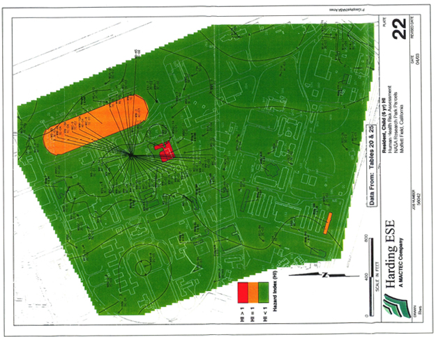
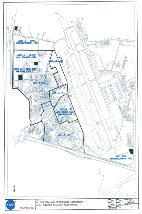
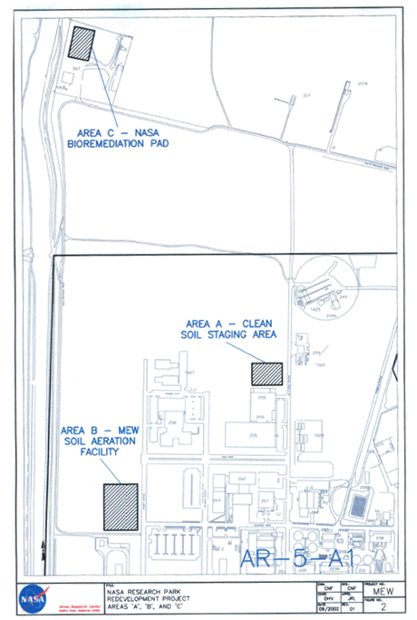
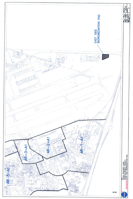
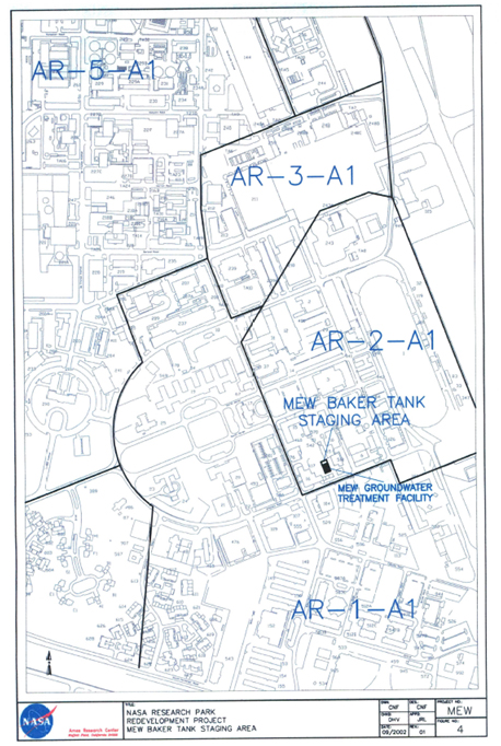
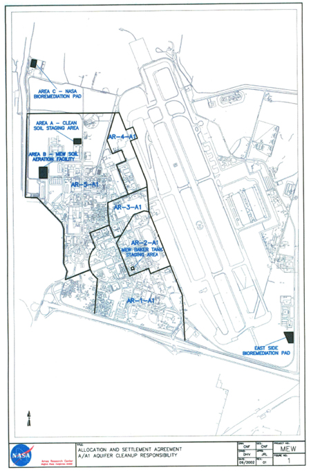
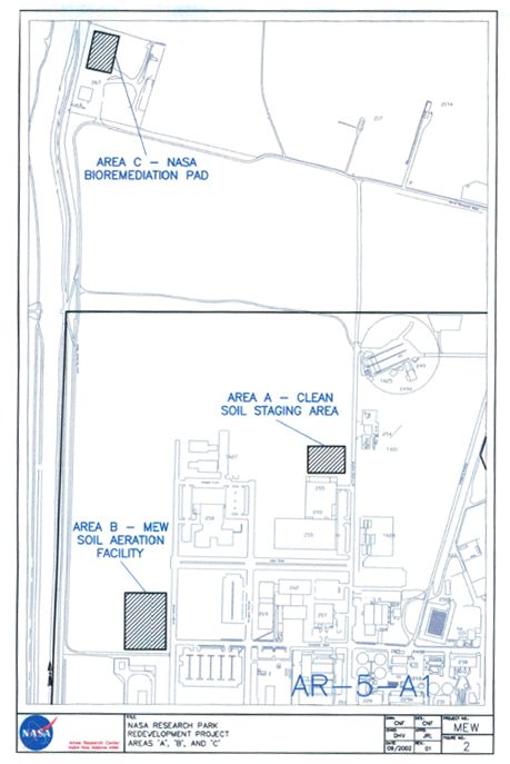
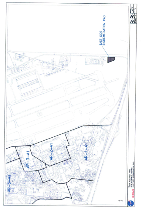
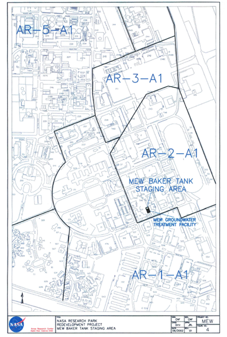

January 28, 2003
56910 002
Xx. Xxxxxx Xxxxxxxx
PAI/ISSi
NASA Xxxx Research Center, MS 19-21
Xxxxxxx Field, California 94035-1000
Lead Impacted Soil Sampling and
Removal Action Workplan Implementation Initial Soil Sample Results
NASA Research Park Xxxxxxx Field, California
Dear Xx. Xxxxxxxx:
This report presents the results of soil sampling performed by MACTEC Engineering and Consulting, Inc. (MACTEC; formerly known as Xxxxxxx ESE, Inc.) for PAI/ISSi at the National Aeronautics and Space Administrations (NASA) Research Park (NRP), Xxxxxxx Field, California. The intent of this investigation was to assess the levels oflead in soil from lead-based paint (LBP) at the NASA NRP, Xxxxxxx Field, California (Site; Plate 1). XXXXXX conducted this assessment and prepared this report under contract to PAI/XXXx on behalf of the NASA Xxxx Research Center.
Background
In July 2002, Xxxxxxx ESE, prepared Lead Impacted Soil Summary Report and Sampling and Removal Action Workplan, NASA Research Park, Xxxxxxx Field, California (Xxxxxxx ESE, 2002) to summarize previous LBP in soil data collected by others at the NRP. That document also presented the following:
| • | A description of additional soil sampling activities (Initial Soil Lead Assessments) for those buildings where the presence of LBP in the building materials is suspected or confirmed |
| • | An outline of removal action activities for areas where previous data has confirmed the presence of LBP in soil |
| • | The process and protocols to be utilized for the Initial Soil Lead Assessment. |
The objective of the Workplan was to identify and develop removal procedures for soil that contains lead exceeding the San Francisco Regional Water Quality Control Board (SFRWQCB) risk-based screening level (RBSL) and to confirm that this cleanup level is not exceeded after soil removal activities. Based on a residential land use scenario, the RBSL for lead in surface soils (<3 meters (m) in depth) used for NRP is 200 milligrams per kilogram (mg/kg).
MACTEC Engineering and Consulting, Inc.
00 Xxxxxxx Xxxxx
Novato, CA 94949
000-000-0000 • Fax: 000-000-0000
January 28, 2003
56910 002
Xx. Xxxxxx Xxxxxxxx
PAI/ISSi
Page 2
On the basis of the review of previous data, MACTEC identified multiple buildings/areas where lead-impacted soils were identified or suspected. On October 24, 2001, Xxxxxxx ESE conducted a site visit to inspect these buildings/areas and to identify those that were surrounded by soil. Buildings/areas surrounded by paved surfaces were not included for soil lead assessments. The areas identified for initial soil lead assessments are the pre-1978 buildings with the potential for lead based paint (Xxxxxxx ESE, 2002). The sampling locations are shown on Plates 2 through 12. In addition, a building/area’s previous use was also considered. For example, Building 38 (Area 2, Parcel 1) is and has historically been tennis courts. Therefore, LBP impacts were not suspected and sampling was not recommended.
Field Investigation
MACTEC collected samples from the Site on September 17 and 18, 2002, in accordance with protocols outlined in the workplan. The samples were collected using a stainless steel trowel and immediately transferred to clean four-ounce glass jars. The soil assessment included collecting a suite of composite samples in unpaved areas at the building comers, near suspect discharge points such as downspouts, and at regular intervals around the periphery of the building. The sampling grid consisted of six samples collected from cells up to 30-feet long by 20-feet wide. Samples were collected from 0 to 6 inches below the surface at the dripline or no more than 2-feet from the building wall if the dripline was not apparent.
Six samples per cell were collected and the samples from each cell were thoroughly mixed and composited in accordance with ASTM Standard D-6051-96 (ASTM, 1996). The samples were labeled and transported under chain of custody procedures to a state-certified analytical laboratory for total lead analysis by EPA Test Method 6010. Samples with total lead concentrations greater than 50 mg/kg were also analyzed for teachable lead using the Waste Extraction Test (WET) method in accordance with the Workplan.
Upon inspection of the site and discussion with Mr. Xxx Xxxxxxxx of PAl/ISSi, ten building locations were established and sampled. Several sites were eliminated from the original sampling program due to the soil bed being a veneer of soil over an asphaltic concrete (AC) pavement. One building was a transite roofed open structure on steel poles above a recreational barbecue area. Two additional building locations, Area 10 buildings 512C and 547B were added by request. Sampling locations are shown on Plates 2 (overview) through 12 and are summarized as follows:
| Area 2 |
||
| Building 24 |
6 samples | |
| Area 3 |
||
| Building 943 |
6 samples | |
January 28, 2003
56910 002
Xx. Xxxxxx Xxxxxxxx
PAI/ISSi
Page 3
| Area 4 | ||
| Building 510 | 6 samples | |
| Area s | ||
| Building 29 | 2 samples (discrete sample and duplicate collected at east side downspout) | |
| Are 6b | ||
| Building 3 | 72 sample | |
| Area 7 | ||
| Building 533 | 6 samples | |
| Area 9 | ||
| Building 113 | 6 samples (one exposed soil location only) | |
| Area 10 | ||
| Building 512C | 24 samples Area IO | |
| Building 547B | 6 samples | |
| Area 11 | ||
| Building 329 | 6 samples (samples collected from voids in the AC surfacing where accessible) | |
Field Investigation
Analytical Results
Table 1 summarizes the total lead results of the soil composites and the corresponding teachable lead results for samples yielding results greater than or equal to 50 mg/kg total lead. The analytical reports and chain of custody documentation are presented in Appendix A.
MACTEC’s evaluation of the analytical data is summarized as follows:
| • | With the exception of the sample collected from Building 113, Area 9, all total lead results were below the 200 mg/kg RBSL. Lead was detected at a concentration of 990 mg/kg in the sample collected from Building 113. Lead was detected in the remainder of the samples at concentrations between 14 and 170 mg/kg. |
| • | Samples from 22 locations (Building 3 [11 locations and one duplicate sample], Building 24 [original and duplicate samples], Building 29 [original and duplicate samples], Building 113, Building 329, Building 510, Building 512C, Building 533, and Building 943) exceeded 50 mg/kg and were analyzed for teachable lead using the WET method. |
| • | The teachable lead results for samples from Building 3 (East side of building, north end 1”1 inset), Building 29 (original and duplicate samples), Building 113 and Building. 510) were at or above the STLC threshold of 5.0 milligrams per liter (mg/L) as cited in Title 22, California Code of Regulations. It should be noted that the sample location at Building 29 represents materials washed into the gutters and deposited on the AC surfacing materials surrounding the building and do not necessarily indicate soil concentrations below the AC cover. |
January 28, 2003
56910 002
Xx. Xxxxxx Xxxxxxxx
PAI/ISSi
Page 4
Summary
Based on the results of the sampling, soil from the vicinity of Building 113, exceeds the NASA RBSL of 200 mg/kg. Prior to building demolition, soil in the vicinity of this building will require removal and disposal as Class I hazardous waste because the teachable lead concentration exceeded the STLC. Confirmation sampling of soil below the excavated area will need to be performed in accordance with procedures outlined in the Workplan developed for the NRP. All other sample results were below the NASA RBSL and soil at these building locations does not require additional investigation or removal.
Based on the results of the leachable lead analysis, soil in the vicinity of Buildings 3 (East side of building, north end 111 inset), 29, 113 and 510 has leachable lead concentrations that exceed the STLC threshold of 5.0 mg/L. Because the soil did not exceed the RBSL, it is acceptable for the soil to be left in place. However, if the soil is to be excavated and moved elsewhere, then the soil must be disposed of as a Class I waste because the leachable lead concentrations exceeded the STLC threshold.
Due to the limited nature of the sampling program, it is possible that concealed materials above the RBSL or hazardous waste levels may be present or encountered during excavation or other intrusive activities. Ifother hazardous materials are discovered during excavation or construction activity, work should cease and NASA soil screening policy and procedures should be implemented to determine the nature and extent of the encountered hazard.
If you have questions or would like additional information, please contact Xxxx Xxxxxxxxx at (000) 000-0000
| Very truly yours, |
| MACTEC Engineering and Consulting, Inc. |
| Xxxxxxx X. Xxxxxxxx, CSST 96-2072 |
| Staff Environmental Scientist |
| XXXxxxxxxx@xxxxxx.xxx |
January 28, 2003
56910 002
Xx. Xxxxxx Xxxxxxxx
PAI/ISSi
Page 5
Xxxx X. Xxxxxxxxx
Senior Geologist
XXXxxxxxxxx@xxxxxx.xxx
MW/Gl./kb/KBS9306.DOC-NASA
| Attachments: |
Plate 1. Site Vicinity Map | |
| Plate 2. Base Map, Soil/Lead Sampling Plates 3-12. Sampling Locations | ||
| Table 1. Summary of Soil Analytical Results | ||
| Appendix. A. Laboratory Analytical Results and Chain of Custody Forms |
References
American Society for Testing and Materials (ASTM), 1996. Guide D6051-96(2001) Standard Guide for Composite Sampling and Field Subsampling for Environmental Waste Management Activities.
MACTEC Engineering and Environmental Services, Inc. (MACTEC) 2002. Lead Impacted Soil Summary Report and Sampling and Removal Action Workplan, NASA Research Park, Xxxxxxx Field, California. July 24.
January 28, 2003
56910 002
Xx. Xxxxxx Xxxxxxxx
PAI/ISSi
Page 6
Distribution
January 28, 2003
56910 002
Xx. Xxxxxx Xxxxxxxx
PAI/ISSi
Page 7
PLATES
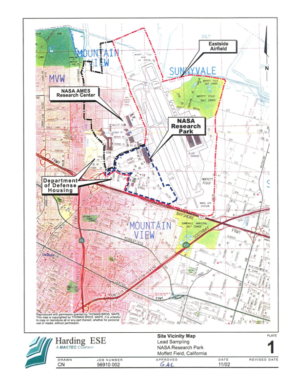
[Plate 1]
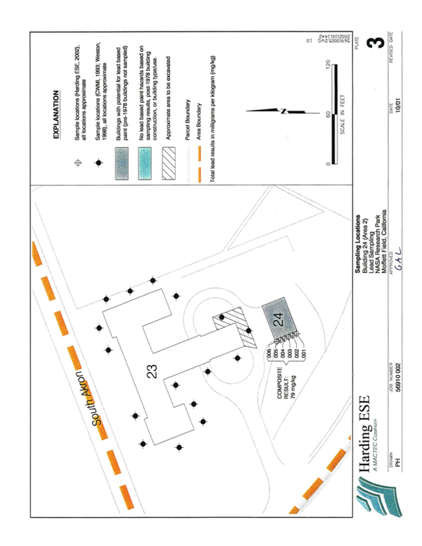
[Plate 2]
2
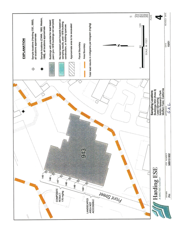
[Plate 3]
3
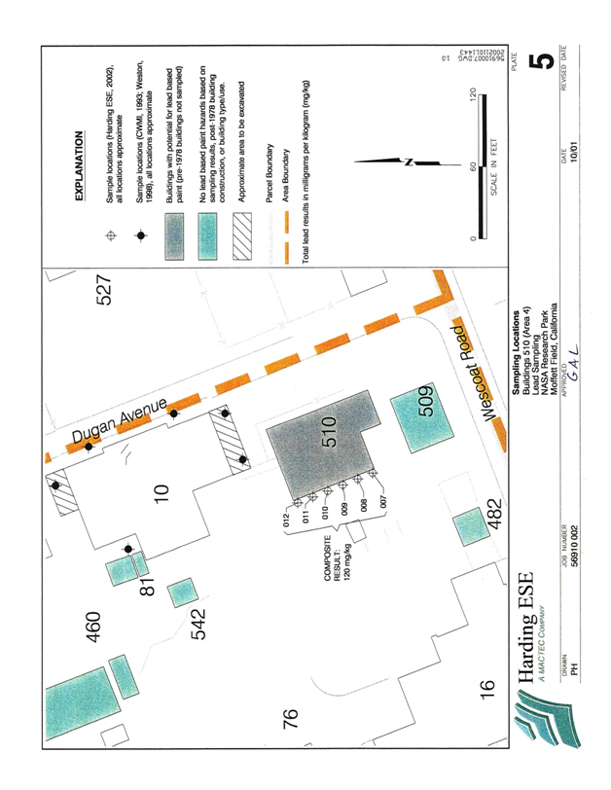
[Plate 4]
4
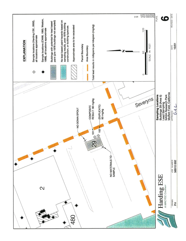
[Plate 5]
5
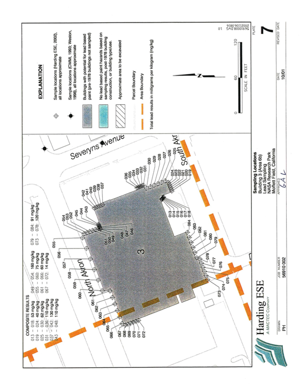
[Plate 6]
6
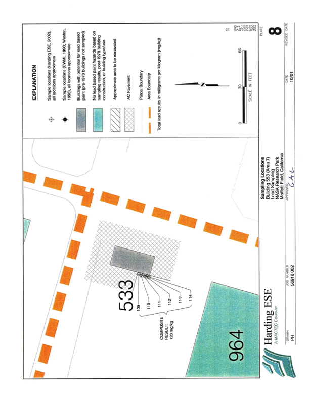
[Plate 7]
7
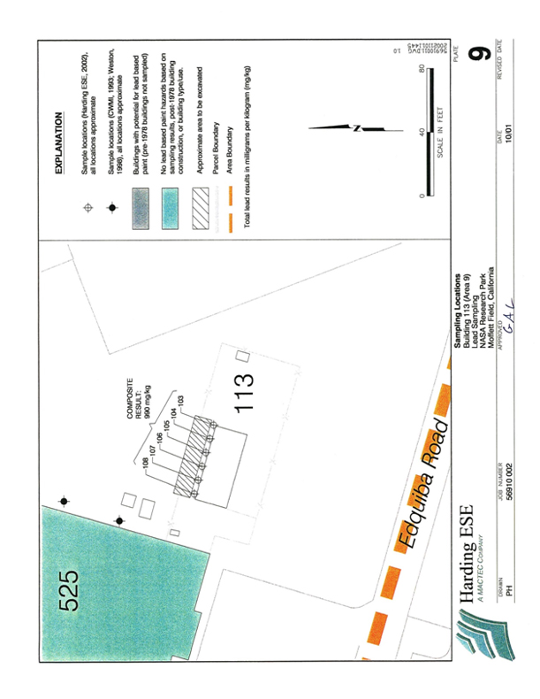
[Plate 8]
8
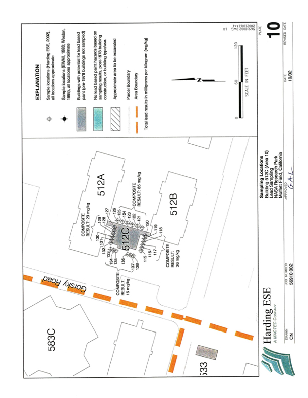
[Plate 9]
9
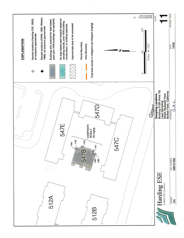
[Plate 10]
10
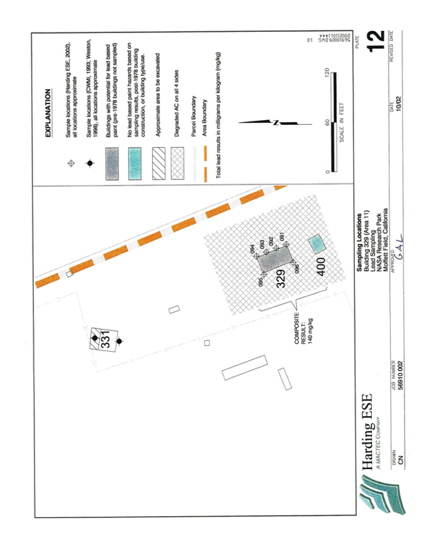
[Plate 11]
11
TABLES
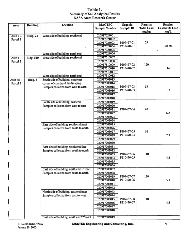
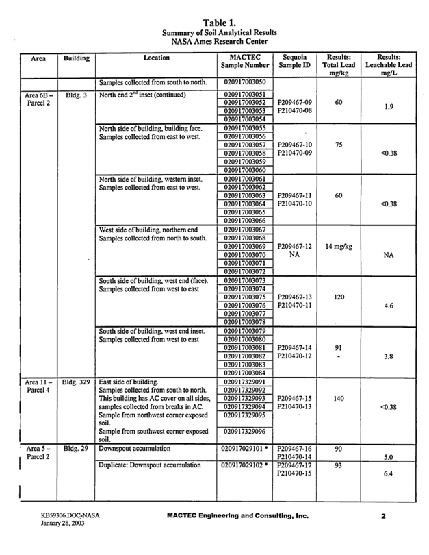
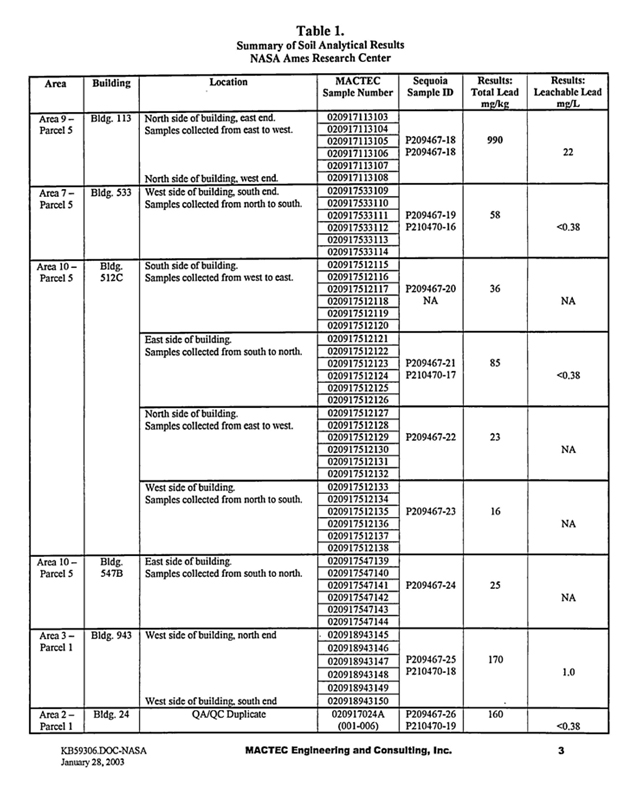
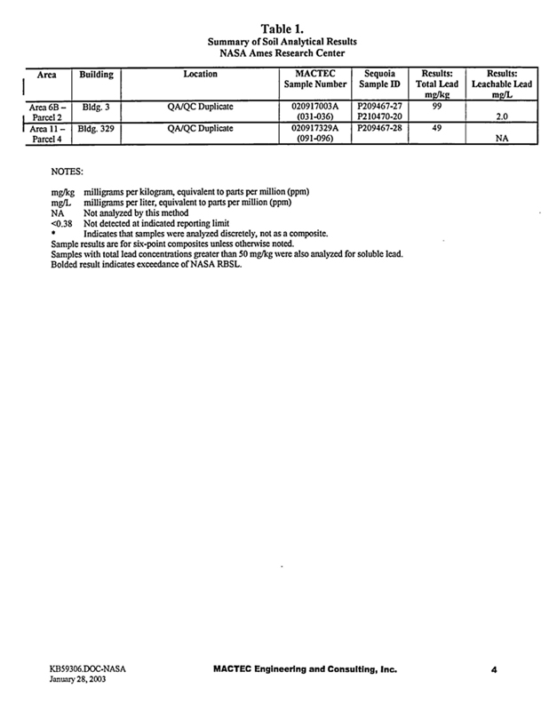
APPENDICES

4 October, 2002
Xxxx Xxxxxxxxx Xxxxxxx ESE
00 Xxxxxxx Xxxxx
Novato, CA 94949
RE: General Commercial
Sequoia Work Order: P209467
Enclosed are the results of analyses for samples received by the laboratory on 09/19/02 13:00. If you have any questions concerning this report, please feel free to contact me.
Sincerely,
Xxxxxxxx X. Xxxxx
Project Manager
CA ELAP Certificate #2374
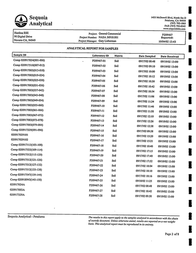
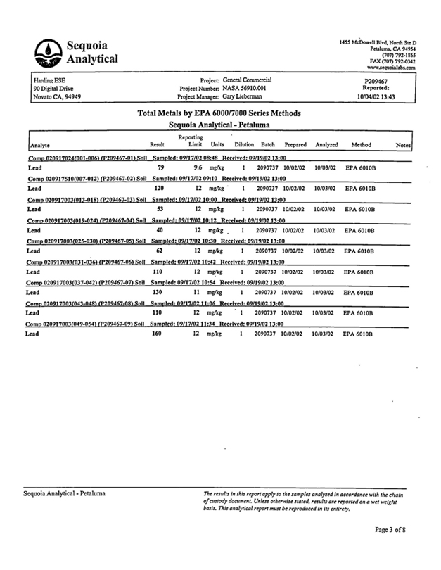
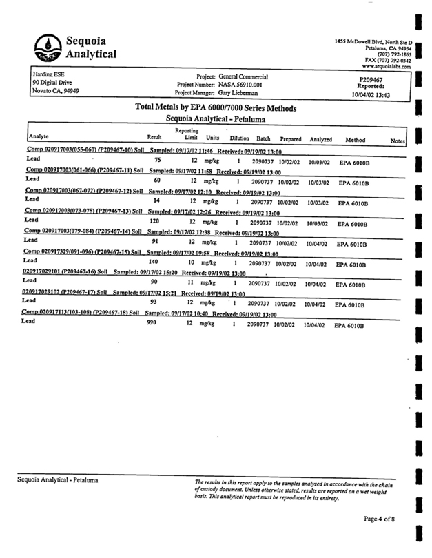
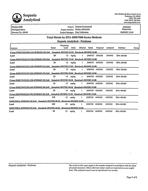
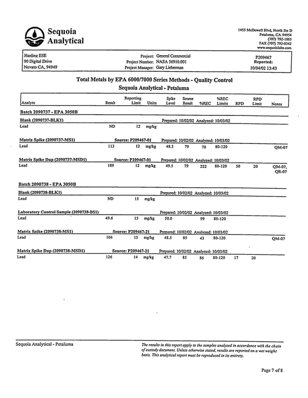

29 October, 2002
Xxxx Xxxxxxxxx Xxxxxxx ESE
00 Xxxxxxx Xxxxx
Novato, CA 94949
RE: General Commercial Sequoia Work Order. P210470
Enclosed are the results of analyses for samples received by the laboratory on 10/21/02 06:35. If you have any questions concerning this report, please feel free to contact me.
| Sincerely, |
| Xxxxxxxx X. Xxxxx Project Manager |
CA ELAP Certificate #2374
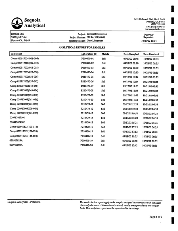
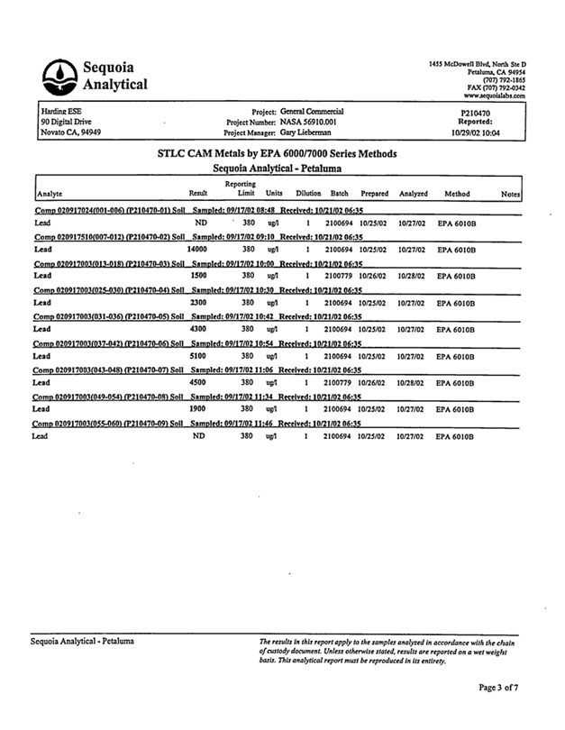
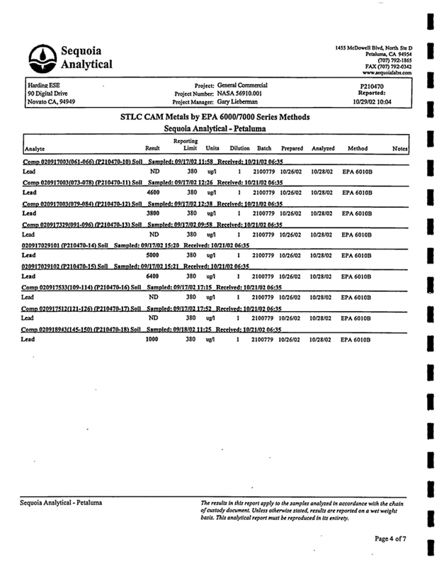
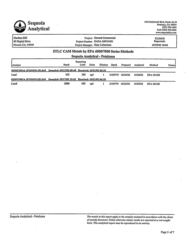
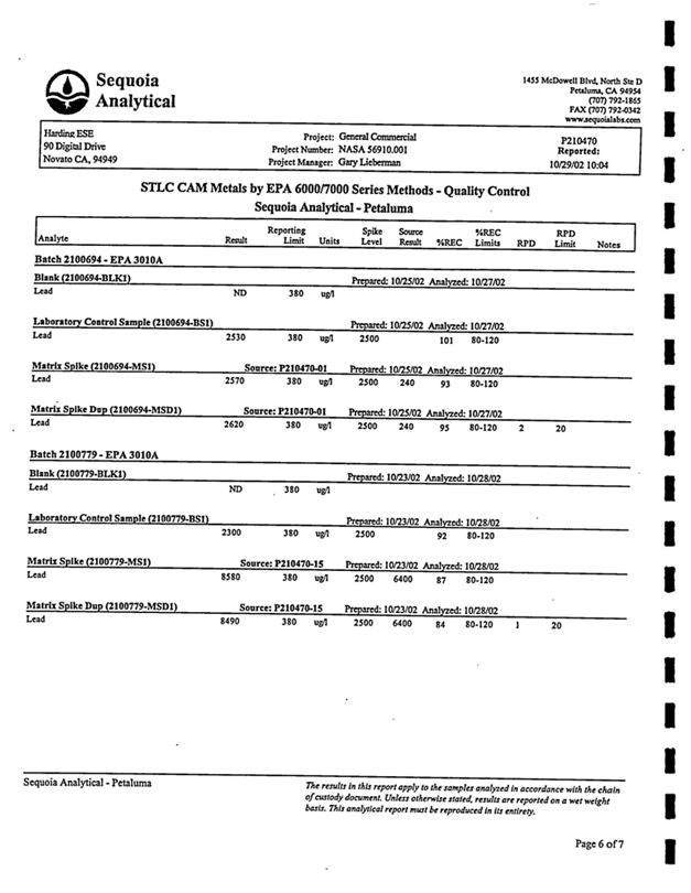

18 October, 2002
Xxxx Xxxxxxxxx Xxxxxxx ESE
00 Xxxxxxx Xxxxx
Novato, CA 94949
RE: General Commercial Sequoia Work Order: P209467
Enclosed are the results of analyses for samples received by the laboratory on 09/19/02 13:00. If you have any questions concerning this report, please feel free to contact me.
| Sincerely, |
| Xxxxxxxx X. Xxxxx Project Manager |
CA ELAP Certificate #2374
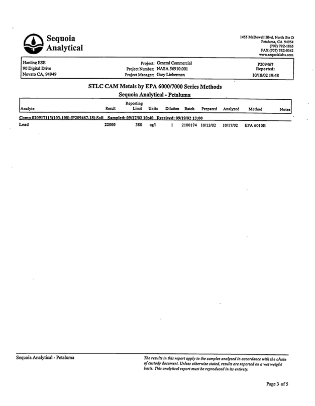
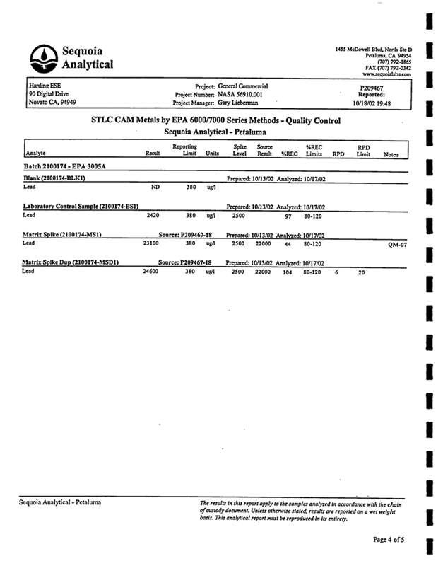
Environmental Baseline Survey
NASA Research Park Parcel 5
Xxxxxxx Federal Airfield
Xxxxxxx Field, California
Prepared for
| PAI/ISSI |
| NASA Xxxx Research Center |
| Xxxxxxx Field, California 94035-1000 Xxxxxxx ESE Project No. 50487 32 |
|
|
| Xxxx X. Xxxxxxxxx |
| Senior Geologist |
|
|
| Xxxxx Xxxxxx RG |
| Principal Geologist |
December 28, 2000

2
Environmental Baseline Survey
NASA Research Park Parcel 5
Xxxxxxx Federal Airfield
Xxxxxxx Field, California
Xxxxxxx ESE Project No. 50487 32
This document was prepared by Xxxxxxx ESE, Inc (Xxxxxxx ESE, formerly Xxxxxxx Xxxxxx Associates) at the direction of PAI/ISSI for the sole use of PAI/ISSI, NASA, the U.S. Environmental Protection Agency, the California Environmental Protection Agency, Department of Toxic Substances Control, the California Environmental Protection Agency, Regional Water Quality Control Board, the U.S. Navy, the Middlefield-Xxxxx-Xxxxxxx (MEW) Companies, and prospective NASA partners, the only intended beneficiaries of this work. No other party should rely on the information contained herein without the prior written consent of the PAI/ISSI and NASA. This report and the interpretations, conclusions, and recommendations contained within are based in part on information presented in other documents that are cited in the text and listed in the references. Therefore, this report is subject to the limitations and qualifications presented in the referenced documents.
CONTENTS
| 1.0 |
INTRODUCTION |
1 | ||||||||||
| 1.1 |
Purpose |
1 | ||||||||||
| 1.2. |
Procedures for Conducting an Environmental Baseline Survey |
2 | ||||||||||
| 1.3 |
Limitations |
2 | ||||||||||
| 1.4 |
Document Organization |
3 | ||||||||||
| 2.0 |
SURVEY METHODOLOGY |
4 | ||||||||||
| 2.1. |
Approach and Rationale |
4 | ||||||||||
| 2.2. |
Program Review |
4 | ||||||||||
| 2.3 |
Document Review |
5 | ||||||||||
| 2.4 |
Interviews |
5 | ||||||||||
| 3.0 |
BACKGROUND |
6 | ||||||||||
| 3.1. |
Physical Setting |
6 | ||||||||||
| 3.2. |
History |
6 | ||||||||||
| 3.3 |
Environmental Setting |
7 | ||||||||||
| 3.3.1 |
Physical Characteristics |
7 | ||||||||||
| 3.3.1.1 |
Surface Features |
7 | ||||||||||
| 3.3.1.2 |
Surface Water |
8 | ||||||||||
| 3.3.1.3 |
Meteorology and Climatology |
8 | ||||||||||
| 3.3.1.4 |
Geology |
9 | ||||||||||
| 3.3.1.5 |
Hydrogeology |
9 | ||||||||||
| 3.3.1.6 |
Habitat and Threatened or Endangered Species |
10 | ||||||||||
| 3.3.1.7 |
Archeological Resources |
12 | ||||||||||
| 3.4 |
Environmental Restoration Programs |
13 | ||||||||||
| 3.4.1 |
Installation Restoration Program |
14 | ||||||||||
| 3.4.2 |
Groundwater Contamination – West Side Aquifers/Regional Groundwater Plume North of 101 |
15 | ||||||||||
| 3.4.3 |
Risk Assessments |
16 | ||||||||||
| 3.5 |
Environmental Compliance Programs |
17 | ||||||||||
| 3.5.1 |
Hazardous Materials and Waste Management |
17 | ||||||||||
| 3.5.2 |
Storage Tanks |
18 | ||||||||||
| 3.5.3 |
Medical/Biohazardous Waste |
18 | ||||||||||
| 3.5.4 |
Lead-Based Paint |
19 | ||||||||||
| 3.5.5 |
Spent Abrasive Materials |
19 | ||||||||||
| 3.5.6 |
Radioactive Materials |
19 | ||||||||||
| 3.5.7 |
Mixed Waste |
20 | ||||||||||
| 3.5.8 |
Radon |
20 | ||||||||||
| 3.5.9 |
Storm Water Discharges and System |
20 | ||||||||||
| 3.5.10 |
Wastewater |
21 | ||||||||||
| 3.5.11 |
Air Quality |
21 | ||||||||||
| 3.5.12 |
Emissions Inventory |
22 | ||||||||||
| 3.5.13 |
Indoor Air Testing |
22 | ||||||||||
| 3.5.14 |
Building 566 Passive Gas Monitoring Survey |
23 | ||||||||||
i
| 3.5.15 |
Asbestos |
24 | ||||||||||
| 3.5.16 |
Pesticides |
24 | ||||||||||
| 3.5.17 |
Polychlorinated Biphenyls |
25 | ||||||||||
| 3.5.18 |
Ordinance |
25 | ||||||||||
| 3.5.19 |
Mold |
25 | ||||||||||
| 3.6 |
Closure Plans |
26 | ||||||||||
| 4.0 |
FINDINGS FOR PARCEL 5 |
27 | ||||||||||
| 4.1 |
History and Current Usage |
27 | ||||||||||
| 4.2 |
Environmental Restoration Programs |
27 | ||||||||||
| 4.2.1 |
Site 10 |
28 | ||||||||||
| 4.2.2 |
Site 14 |
28 | ||||||||||
| 4.2.3 |
Site 15 |
28 | ||||||||||
| 4.2.4 |
Site 16 |
29 | ||||||||||
| 4.2.5 |
Site 18 |
29 | ||||||||||
| 4.3 |
Environmental Compliance Programs |
29 | ||||||||||
| 4.3.1 |
Hazardous Waste Management |
29 | ||||||||||
| 4.3.2 |
Hazardous Materials Management |
29 | ||||||||||
| 4.3.3 |
Storage Tanks |
29 | ||||||||||
| 4.3.3.1 |
Underground Storage Tanks, Oil/Water Separators and Sumps |
29 | ||||||||||
| 4.3.3.2 |
Aboveground Storage Tanks |
30 | ||||||||||
| 4.3.4 |
Lead-Based Paint |
30 | ||||||||||
| 4.3.5 |
Air Quality |
30 | ||||||||||
| 4.3.6 |
Asbestos |
31 | ||||||||||
| 4.3.7 |
Polychlorinated Biphenyls |
31 | ||||||||||
| 4.4 |
Discussion of Findings |
31 | ||||||||||
| 5.0 |
BIBLIOGRAPHY |
33 | ||||||||||
TABLES
| 1. |
History of Installation Operations | |
| 2 |
Installation Restoration Program Sites | |
| 3 |
Underground Storage Tank Status | |
| 4 |
Aboveground Storage Tank Status | |
| 5 |
Lead Sampling Results | |
| 6 |
Asbestos Survey/Sampling Results | |
ii
| 7 |
PCB Impacted Transformers/Capacitors | |
| 8 |
Building List Summary | |
| 9 |
Monitoring and Extraction Well Ownership and Total Depth | |
| 10 |
Former Hazardous Materials and Waste Locations | |
| 11 |
Current Hazardous Materials and Waste Locations | |
| PLATES | ||
| 1. |
Site Vicinity Map | |
| 2 |
Site and Parcel Location Map | |
| 3 |
IRP Location Map | |
| 4 |
Well and Treatment System Location Map | |
| 5 |
Storage Tank Location Map | |
| 6a |
Utility Location Map #1 | |
| 6b |
Utility Location Map #2 | |
| APPENDICES | ||
| A |
PARCEL ENVIROMENTAL SUMMARYR REPORTS | |
| B |
PLUME AND ALLOCATION MAPS | |
| C |
BURROWING OWL LOCATION MAP | |
| D |
ARCHEOLOGICAL SENSITIVE AREAS | |
| DISTRIBUTION | ||
iii
ACRONYMS
| 1,1,l-TCA |
I, I, I-Trichloroethane | |
| 1,2-DCA |
1,2-Dichloroethane | |
| 1,1-DCA |
1,1-Dichloroethane | |
| 1,1,2-TCA |
1,1,2-Trichloroethane | |
| 1,1-DCE |
1,1-Dichloroethene | |
| 1,2-DCE |
cis and trans-1,2 -dichloroethene | |
| ACGIH |
American Conference of Governmental Industrial Hygienists | |
| ACM |
Asbestos Containing Material | |
| AOis |
Areas of Investigation | |
| AST |
Aboveground Storage Tank | |
| BRAC |
Base Realignment & Closure Program | |
| CalEPA |
California Environmental Protection Agency | |
| CANG |
California Air National Guard | |
| CERCLA |
Comprehensive Environmental Response, Compensation and Liability Act | |
| CP |
Closure Plan | |
| DFG |
California Department of Fish and Game | |
| DOI |
Department of the Interior | |
| DTSC |
Department of Toxic Substances Control | |
| EA |
Endangerment Assessment | |
| EBS |
Environmental Baseline Survey | |
| ESAs |
Environmental Site Assessments | |
| FEMA |
Federal Emergency Management Agency | |
| FFA |
Federal Facilities Agreement | |
| FOSL |
Finding of Suitability to Lease | |
| FS |
Feasibility Study | |
| Xxxxxxx ESE |
Xxxxxxx ESE, Inc. | |
| HHRA |
Human Health Risk Assessment | |
| HWAAs |
Hazardous Waste Accumulation Areas | |
| HWMP |
Hazardous Waste Management Plan | |
| IRP/OU |
Installation Restoration Program and Operable Units | |
| LBP |
Lead-Based Paint | |
| LTA |
Lighter-Than-Air | |
| MCLs |
Maximum Contaminant Levels | |
| MFA |
Xxxxxxx Federal Airfield | |
| MSL |
Mean Sea Level | |
| NACA |
National Advisory Committee for Aeronautics | |
| NAS |
Naval Air Station | |
| NASA |
National Aeronautics and Space Administration | |
| National Register |
National Register of Historic Places | |
| NEX |
Navy Exchange | |
| NPDES |
National Pollutant Discharge Elimination System |
iv
| NPL |
National Priorities List | |
| OF |
Fahrenheit | |
| OSHA |
Occupational Safety & Health Administration | |
| PA |
Preliminary Assessment | |
| PCBs |
Polychlorinated Biphenyls | |
| PCE |
Tetrachloroethene | |
| PELs |
Permissible Exposure Limits | |
| PRGs |
Preliminary Remediation Goals | |
| RI |
Remedial Investigation | |
| RI/FS |
Remedial Investigation/Feasibility Study Program | |
| ROD |
Record of Decision | |
| RWQCB |
California Regional Water Quality Control Board | |
| STLC |
Soluble Threshold Limit Concentration | |
| SWEA |
Station-Wide Ecological Assessment | |
| TCE |
Trichloroethene | |
| TLV-TWAs |
Threshold Limit Values-Time Weighted Averages | |
| USACE |
U.S. Army Corps of Engineers | |
| USEPA |
U.S. Environmental Protection Agency | |
| USFWS |
United States Fish and Wildlife Service | |
| UST |
Underground Storage Tank | |
| VOCs |
Volatile Organic Compounds | |
| WATS |
West-Side Aquifers Treatment Systems |
v
1.0 INTRODUCTION
Xxxxxxx ESE has prepared this Environmental Baseline Survey (EBS) to present the results of the assessment of known existing environmental conditions for Parcel 5 at Xxxxxxx Federal Airfield (MFA), formerly part of Naval Air Station (NAS) Xxxxxxx Field (NAS Xxxxxxx Field), California. The subject parcels are heretofore referred to as the NASA Research Park (NRP) Parcels. The location of Xxxxxxx Field is shown on Plate 1 and the NRP is shown on Plate 2. Xxxxxxx ESE conducted the assessment and prepared this report under contract to PAI/XXXX on behalf of NASA Xxxx Research Center.
As shown on Plate l, the NRP Parcels are located along the southern boundary of the Xxxxxxx Field and comprise an area of approximately 213 acres that is being planned for redevelopment as a collaborative research and educational campus. As discussed above and in Section 2.0, the area is within Xxxxxxx Field, which was continuously operated by the U.S. military since it was commissioned in 1933 until it was transferred to the National Aeronautics and Space Administration (NASA) in 1994. As described in the Xxxxxxx Field Comprehensive Use Plan, Environmental Assessment (Xxxxx & Associates, i994), portions of Xxxxxxx Field will be converted from their former military use and redeveloped as a laboratory and associated offices. In addition, the remainder of NRP is proposed for development as a collaborative research and educational campus as described in the Notice of intent to Prepare an Environmental impact Statement, published in the Federal Register on June 16, 2000.
| 1.1 | Purpose |
The purpose of the EBS is to 1) summarize the known existing environmental condition of the NRP in a manner that is easy to use by future partners, and 2) evaluate the potential constraints that the existing conditions may have upon future uses. To the extent that the information was available to the authors, the EBS addresses the following:
| • | Status of the site investigations and remediation |
| • | Nature and extent of known contamination, if any |
| • | Hazardous materials and waste management |
| • | Underground storage tanks (UST) and aboveground storage tanks (AST) |
| • | Status of building surveys for asbestos, lead-based paint (LBP), and radon |
| • | Other information pertaining to environmental conditions on the parcel. |
The EBS focuses on identifying and documenting environmental site characterization and remediation activities and the presence or likely presence of hazardous substances and/or hazardous waste on a portion of real property considered for reuse. The EBS addresses hazardous substances or wastes, including certain substances not usually regulated under the Comprehensive Environmental Response, Compensation, and Liability Act (CERCLA), and
1
other substances such as petroleum products, asbestos, LBP, PCBs, and mold in structures to the extent that relevant information is available. The EBS considers soil and groundwater contamination, and a description of potential public health and safety issues, for example, those associated with the soil or groundwater contamination or the condition of buildings, that may affect NASA’s ability or decision to redevelop such property. The EBS does not constitute a complete site characterization because it is based on existing available information. In addition, no confirmation/field verification was conducted.
| 1.2 | Procedures for Conducting an Environmental Baseline Survey |
Procedures for conducting an EBS are described in the DoD guidance (U.S. DoD, 1994). The EBS is similar to CERCLA Preliminary Assessment (PA) and may include information from many sources, including ongoing programs, such as CERCLA remedial investigation and remediation, building surveys for asbestos, LBP, and radon, solid and hazardous waste management activities, and other programs, as discussed in Section 2.0. Specific EBS activities may include the following:
| • | Search, review, and documentation of existing records regarding environmental conditions on the parcel |
| • | Description of known current or past activities on the parcel |
| • | Interviews with current and/or former employees involved in operations on the parcel |
| • | Description of known hazardous substance or hazardous waste management practices on the parcel and on adjacent parcels |
| • | Documentation of observations made during visual and physical inspections (Not conducted for this EBS) |
| • | Description of possible sources of contaminants on the parcel or on adjacent parcels, on the basis of available information |
| 1.3 | Limitations |
This document was prepared at the direction of PAI/ISSI for the sole use of PAI/ISSI, NASA, the U.S. Environmental Protection Agency (USEPA), the California Environmental Protection Agency (CalEPA), Department of Toxic Substances Control (DTSC), the Cal-EPA, Regional Water Quality Control Board (RWQCB), the U.S. Navy, the Middlefield-Xxxxx-Xxxxxxx (MEW) Companies, and prospective NASA partners, the only intended beneficiaries of our work, to support redevelopment of the NASA Research Park Parcels. No other party should rely on the information contained herein without the prior written consent of NASA and Xxxxxxx ESE.
Xxxxxxx ESE’s professional services for this EBS, including the preparation of this document, were conducted in accordance with practices and procedures generally accepted in the environmental consulting field at this time; no other warranty is given or implied by this report.
2
Information about the presence or absence of hazardous substances in the area discussed in this report is based on limited data and observations. Environmental conditions may change over time and may be different away from locations where data or samples were collected or observations made. Xxxxxxx ESE does not and cannot have complete knowledge of environmental conditions in the area discussed. Furthermore, this report is complete and accurate only to the extent that cited reports and agency information are complete and correct, and to the extent that all relevant information has been provided to Xxxxxxx ESE. The purpose of the EBS is to identify and describe available information. In the EBS, Xxxxxxx ESE has not attempted to independently verify the completeness or accuracy of the information presented, or to independently assess the environmental condition of the described area.
| 1.4 | Document Organization |
The remainder of this report is organized as follows:
| • | Section 2.0 provides a description of the methodology used to complete the EBS |
| • | The background of the site including a physical description, history of the facility, the environmental setting including geology, hydrogeology, surface water, threatened or endangered species and sensitive habitat, and. archeological resources, and a summary of the environmental restoration and compliance programs is presented in Section 3.0 |
| • | Sections 4.0 describes the Findings for Parcel 5 |
| • | References are provided in Section 5.0 |
| • | A summary of the information for Parcel 5 is presented in Appendix A |
| • | Appendix B presents plume and environmental cleanup allocation maps for the NRP |
| • | Burrowing owl locations and archeologically sensitive areas are presented in Appendix C and D, respectively. |
3
2.0 SURVEY METHODOLOGY
| 2.1 | Approach and Rationale |
A systematic process was followed in which all available reports, records, maps, and interviews were analyzed. Reported conditions were evaluated to determine their impact on the characterization, remediation, reuse, and occupation of the NRP. On the basis of this information, conclusions were drawn relative to the environmental condition of the NRP. As discussed previously, physical inspections of the NRP to identify any new potential environmental concerns or to verify information obtained during the records review, were not conducted as part of this EBS.
Analysis of the ongoing or completed environmental programs at Xxxxxxx Field included the following:
| • | Building surveys for asbestos and lead based paint (LBP) |
| • | Building surveys for mold |
| • | Radon monitoring (limited to residential units and NASA buildings not within the NRP) |
| • | Management of electrical transformers containing polychlorinated biphenyls (PCBs) |
| • | Underground and aboveground storage tank (USTs and ASTs) management |
| • | Basewide Remedial Investigation/Feasibility Study Program (Rl/FS) |
| • | Installation Restoration and Operable Unit Programs (IRP/OU) |
| • | Stormwater Pollution Prevention Plan implementation |
| • | Hazardous Waste Management, Minimization and Spill Contingency Plans |
| • | Assessment of impacts from adjoining properties (MEW Superfund Site) |
| • | Evaluation of air quality. |
Results of each of these programs for Parcel 5 are described in Section 4.0.
| 2.2 | Program Review |
A review of the ongoing environmental restoration and compliance programs (discussed above) for the NRP was performed. NASA and PAI/ISSI program managers provided relevant and updated program data. The examination of these programs provided a comprehensive overview of the past and current environmental status of the NRP. After data evaluation the information was entered into Parcel Summary tables to facilitate record access and summary report production. The table for Parcel 5 is included as Appendix A to support the evaluation of the environmental condition of the NRP.
4
| 2.3 | Document Review |
The document review process focused on identifying parcel specific surveys, inspections, studies, field investigations, and interim and final remedial measures especially those completed subsequent to transfer of the NRP from the Navy.
Documents and information reviewed for this EBS include the following type of reports or investigative and management plans:
| • | Site reuse plans |
| • | Building preliminary assessment/site inspections |
| • | Work plans and sampling and analysis plans |
| • | Remedial Investigation and Feasibility Study Reports |
| • | Building construction information for buildings |
| • | Results of building surveys for asbestos, LBP, radon, PCBs, and hazardous material/waste |
| • | Inventories and management plans for USTs and ASTs |
| • | Air monitoring reports/emissions inventories. |
A complete list of the documents reviewed is provided in Section 5.0.
| 2.4 | Interviews |
Interviews were conducted with NASA and PAI/ISSI staff familiar with historic and current environmental restoration and compliance programs. Interviews with past and present employees who worked in the buildings located within the NRP were not performed as part of this EBS. Mr. Xxxxxx Xxxx of the Cal/EPA Regional Water Quality Control Board and Xx. Xxxxxxx Xxxxx of the U.S. EPA were contacted regarding the environmental restoration programs.
5
3.0 BACKGROUND
This section presents relevant information about Xxxxxxx Field with an emphasis on the NASA Research Park Parcels. It includes a description of the physical setting, the history of Xxxxxxx Field, a summary of the environmental setting, and the environmental restoration and compliance programs. Xxxxxxx Field includes NASA Xxxx Research Center and MFA. Xxxxxxx Field also includes the Army housing; however, the housing is not operated by NASA and is not included in this report.
| 3.1 | Physical Setting |
Xxxxxxx Field lies 35 miles south of San Francisco, 10 miles north of San Xxxx, and about 1 mile south of San Francisco Bay (Plate 1). The facility encompasses about 2,000 acres in Santa Xxxxx County and borders the cities of Mountain View and Sunnyvale, California. To the north of Xxxxxxx Field are saltwater evaporation ponds and wetlands associated with San Francisco Bay; Stevens Creek lies to the west; U.S. Highway 101 runs along the southern perimeter; and Lockheed-Xxxxxx Aerospace facilities are located to the east. NASA Xxxx Research Center is in the northwest portion of Xxxxxxx Field. The area south of U.S. 101 is and has been industrial and includes a group of companies located or formerly located in a 0.5 square-mile area bounded by East Middlefield Road, Xxxxx Street, Xxxxxxx Road, and U.S. 101 referred to as the MEW Superfund Site. These companies are cleaning up soil and groundwater contamination believed to originate within the MEW Superfund site that has also affected groundwater quality beneath the NRP (Tetra Tech, 1998c).
The NASA Research Park Parcels (Plate 2) are in the southern portion of Xxxxxxx Field and comprise 213 acres. The NASA Xxxx Research Center lies to the north and west of the NRP, U.S. 101 bounds the NRP to the south, and the runways and hangars of Xxxxxxx Federal Airfield lie to the east.
| 3.2 | History |
Since the 19th century, the Xxxxxxx Field area was used for agriculture. Historic maps show a series of landings along the bay with connecting roads, stage stops, and residences in the area. (PRC, 1994).
The U.S. military continuously operated the Naval Air Station (NAS) Xxxxxxx Field from its date of commission in April 1933 as the Sunnyvale Naval Air Station until it was transferred to NASA on July 1, 1994. A summary of the history of the base operations is provided in Table 1. NAS Xxxxxxx Field’s original mission was to serve as a base for the West Coast dirigibles of the lighter-than-air (LTA) program. The Navy continued to use the station as an air base until October 1935 when it was transferred to the Army Air Corps for use as a training base. During the Army’s tenure, the National Advisory Committee for Aeronautics (NACA) established Xxxx Aeronautical Laboratory in December 1939 on land adjacent to the Navy at Xxxxxxx Field.
In April 1942, the base was returned to the Navy and renamed Naval Air Station (NAS) Xxxxxxx Field.
6
By 1950, Xxxxxxx Field was the largest naval air transport base on the West Coast and became the first all- weather air station. Jets first arrived in 1950 and included fighters (F3Ds, F2Hs, and F7Us). In 1953, the base became home to all Navy fixed-wing, land-based antisubmarine craft. A weapons department was formed on the base in 1954.
In 1958, NASA was created and absorbed NACA; thus it became the NASA Xxxx Research Center.
In February 1966, the base activated its high-speed refueling facilities, and in 1973, it became the headquarters of the Commander Patrol Wings, U.S. Pacific Fleet.
Between 1973 and 1994, NAS Xxxxxxx Field’s mission involved support of antisubmarine warfare training and patrol squadrons. At one point, Xxxxxxx Field was the largest P-3 base in the world, with nearly 100 P-3C Orion Patrol aircraft. These aircraft were assigned to nine squadrons supported by 5,500 military, 1,500 civilian, and 1,000 reserve personnel. No heavy manufacturing or major aircraft maintenance was conducted during the last mission; mostly unit- and intermediate-level maintenance occurred.
The base was designated for closure as an active military base under the U.S. Department of Defense Base Realignment and Closure (BRAC) program. The base was transferred in July 1994 to NASA, except the military housing units and associated facilities, which were transferred to Onizuka Air Force Base.
| 3.3 | Environmenyal Setting |
| 3.3.1 | Physical Characteristics |
The following description of physical characteristics discusses surface features, surface water, meteorology and climatology, geology, hydrogeology, and threatened or endangered species and habitat at Xxxxxxx Field.
| 3.3.1.1 | Surface Features |
Xxxxxxx Field is located near the southern end of San Francisco Bay on nearly flat fluvial basin deposits. Elevations range from approximately 36 feet above mean sea level (msl) to 2 feet below msl (IT, 1993). Since topographic relief is minimal, manmade structures are the most noticeable surface features and include buildings, aircraft hangars, roads, parking lots, runways, and landscaped areas.
The eastern and western sides of Xxxxxxx Field are separated by northwest trending runways. Most buildings are located on the western side of Xxxxxxx Field with the most prominent one being the very large Hangar 1 that at one time housed the dirigible, the USS Macon. Features on the eastern side of Xxxxxxx Field include Hangars 2 and 3, the California Air National Guard (CANG) area, a golf course, and other buildings. Most areas surrounding the buildings are landscaped.
The area north of Xxxxxxx Field was once tidal salt marshes and mud flats of San Francisco Bay. These marshes and mud flats have been eliminated or greatly altered by diking and filling (IT, 1993). Currently, commercial saltwater evaporation ponds are present north of Xxxxxxx Field. A stormwater retention pond·exists on lands of Midpeninsula Regional Open Space District and NASA Xxxx.
7
| 3.3.1.2 | Surface Water |
San Francisco Bay, California’s largest estuary, is approximately 1 mile north of Xxxxxxx Field. Historically, tidal salt xxxxx and mud flats covered extensive areas of the southern portion of the bay including the northern portion of Xxxxxxx Field. However, most of these wetlands have been eliminated or greatly altered. The large area north and northeast of Xxxxxxx Field was diked several decades ago and is still used as commercial salt evaporation ponds.
Surface water features at Xxxxxxx Field include or have included stormwater drainage ditches, several small ponds, and a stormwater retention pond. There are no streams on Xxxxxxx Field, although several streams are present to the east and west. Coyote Creek and Xxxxxxxxx Xxxxxx drain into San Francisco Bay east of Xxxxxxx Field, and Stevens Creek drains into San Francisco Bay to the west.
Stormwater in the eastern portion of the airfield (including the runways and aircraft aprons) drains through a system of surface channels (Patrol Road Ditch and Marriage Road Ditch) and subsurface drains to the Building 191 lift station and is pumped into the Northern Channel at its western end. Water is pumped from the eastern end of Northern Channel to Xxxxxxxxx Xxxxxx, which drains to San Francisco Bay. During significant rainfall, temporary lift stations pump water from Patrol Road Ditch and Marriage Road Ditch directly into the Northern Channel.
Stormwater in the western portion of the base drains to the stormwater settling basin via underground pipes. From the settling basin, the water flows northward through the Eastern Diked Xxxxx to the stormwater retention pond.
On the basis of an initial assessment study of Xxxxxxx Field performed by the Naval Energy and Environmental Support Activity (XXXXX), the Federal Emergency Management Agency (FEMA) projects that the eastern portion of Xxxxxxx Field will be inundated by 100-year tidal flooding (XXXXX 1984). The 100-year flood is projected to reach 7.5 feet above msl and a significant portion of Xxxxxxx Field would be affected.
| 3.3.1.3 | Meteorology and Climatology |
Xxxxxxx Field experiences a Mediterranean climate with relatively dry, warm xxxxxxx and cool, wet xxxxxxx (IT 1993). Influences from the Pacific Ocean, San Francisco Bay, and cool valley breezes help to maintain moderate temperatures. The average annual temperature is 58 degrees Fahrenheit (°F). The average monthly temperature in August is 66°F, and the average monthly temperature in January is 50°F. Maximum temperatures have been recorded above 100°F, and minimum temperatures have been recorded as low as 22°F (IT, 1993).
During the day, moderate northern and northwestern winds are common; during the evening, winds are generally from the west (IT, 1993). Occasionally, winter storms are accompanied by severe southwestern winds. The average annual wind velocity is 7 miles per hour.
8
The average annual rainfall is 13.2 inches (IT, 1993). Most precipitation falls during the winter with a dry period from May through September. During December, January, and February, the maximum monthly average precipitation is 2.5 inches, which decreases to between 1 and 2 inches per month during the spring and fall. Rainfall during the dry period is usually less than 0.5 inches per month. Thunderstorms are rare and can occur during any month, but are not usually intense. Snow is rare, and if it does fall, it does not accumulate.
Humidity averages 74 percent, with daily highs of 85 percent and lows of 60 percent (IT, 1993). Much of the humidity is attributed to the site’s proximity to San Francisco Bay.
| 3.3.1.4 | Geology |
Xxxxxxx Field is located at the northern end of the Santa Xxxxx Valley Basin, about I mile south of San Francisco Bay. The Santa Xxxxx Valley Basin is a Pliocene-age, large, northwest-trending structural depression between the San Andreas and Hayward faults. The basin is bordered on the west by the Santa Xxxx Mountains and on the east by the Diablo Range.
Regionally, the Santa Xxxxx Valley contains up to 1,500 feet of interbedded alluvial, fluvial, and estuarine deposits (Iwamura, 1980). Locally, these sediments consist of varying combinations of clay, silt, sand, and gravel that represent interfingering of estuarine and fluvial depositional environments during the late Pleistocene and Holocene epochs. The interfingering of fluvial and estuarine sediments in southern San Francisco Bay is related to world-wide fluctuations in sea level during glacial and interglacial episodes of the late Quaternary period (Tetra Tech, 1998c). The fluvial sediments were derived from the Santa Xxxx highlands west of the basin and deposited on an alluvial plain bounded by alluvial fan deposits to the west and baylands to the northeast (Iwamura, 1980). Surface geologic maps indicate that alluvial fan deposits extend toward the basin approximately to U.S. Highway 101, which forms the southern boundary of Xxxxxxx Field. Shallow deposits on Xxxxxxx Field are branching river and flood plain deposits. Estuarine deposits are found at the extreme northern end of Xxxxxxx Field.
| 3.3.1.5 | Hydrogeology |
Within the northern Santa Xxxxx Valley groundwater basin, watershed boundaries are defined by drainage divides in the Santa Xxxx Mountains and Diablo Range. The contact between the bedrock and Quaternary alluvium defines the extent of the groundwater basin (Tetra Tech, 1998c). Regionally, the Quaternary water-bearing deposits are divided into a deep, confined aquifer, and a shallow, unconfined aquifer based on the extent of a regional confining layer (Tetra Tech, 1998c). Four regional subdivisions of the upper 250 feet of Quaternary sediments are as follows:
| • | Holocene (Recent Interglacial Period) alluvium (A Aquifer zone) |
| • | Late Pleistocene (Wisconsinan Glacial Period) alluvium (B aquifer zone) |
| • | Late Pleistocene (Sangamon) Interglacial deposits (B/C acquitard) |
| • | Pleistocene (Illinoian Glacial Period) alluvium (C aquifer zone). |
9
The shallow aquifer (upper 250 feet) is subdivided into the A, B, and C aquifers. A laterally extensive clay aquitard (B/C aquitard) effectively isolates the C aquifer (160 to 250 feet below ground surface [bgs]) from the upper aquifers. The A/B aquitard may be locally discontinuous.
The remaining discussion focuses on the A aquifer zones beneath the NRP because the aquifer is most accessible and likely to be impacted by contamination and because of the relative lack of contamination in the deeper aquifers.
The A aquifer extends from a depth of 5 to 65 feet bgs at the western side of Xxxxxxx Field. The A aquifer is divided into the Al- and A2- aquifer zones by a discontinuous, low-penneability horizon (A1/A2 aquitard) located between 25 and 30 feet bgs (Tetra Tech, 1998a). The aquifer consists of sands and gravels with gravel comprising 20 to 90 percent of the coarse material. In general, groundwater flow is toward San Francisco Bay (north) with a horizontal gradient of 0.004 to 0.005 feet per feet (ft/ft) (PRC, 1996). Depth to groundwater ranges from 5 to 12 feet bgs (Tetra Tech, 1998a)
| 3.3.1.6 | Habitat and Threatened or Endangered Species |
This section summarizes the types of habitats occurring at Xxxxxxx Field. A comprehensive assessment of Xxxxxxx Field ecology can be found in the Phase II Site wide ecological assessment (SWEA, PRC and Xxxxxxxxxx Xxxxxx [MW], 1997). The habitats at Xxxxxxx Field have been classified into two major categories: (1) wetlands and aquatic, and (2) uplands.
The wetlands and aquatic habitats have been defined using the United States Fish and Wildlife Service (USFWS) classification system and the U.S. Army Corps of Engineers (USACE) system discussed in the WESCO (1993) report. The California Department of Fish and Game (DFG) uses the USFWS protocol for wetland classification. The majority of the wetlands are located in the northern section of Xxxxxxx Field bordering the commercial salt evaporation ponds. These areas help to support a variety of species including some listed as endangered under the federal Endangered Species Act and as California species of special concern.
The uplands habitat can be further divided into levee banks, disturbed grasslands, and landscaped areas. The disturbed grasslands and landscaped areas occur within the NRP.
The levee banks provide limited upland habitat bordering the saltwater and brackish marshes. They range from 5 to 15 feet in height and are mostly covered by grasses and weeds. This type of vegetation provides cover for species such as the California ground squirrel, mourning dove, and various species of rodents. The location of the banks near the marshes makes them a suitable resting area for waterfowl and wading birds between periods of feeding. They also provide a corridor for predatory mammals that can have an adverse effect on the federally endangered and special status species occupying these areas.
The grasslands are highly disturbed areas that provide limited useable habitat for wildlife. These areas are located between buildings and runways and are mowed on a regular basis. The burrowing owl has been observed foraging in these areas. This species is listed as a California special status species. Appendix C presents a map showing the most recent locations where burrowing owls are nesting at Xxxxxxx Field. None of these areas are located within Parcel 5.
10
Specific mitigation measures have been developed for areas where burrowing owls have been identified and are as follows:
| 1) | Early in the planning process, review all proposed projects, programs, and activities to determine if they may occur near (i.e., within 250 feet) areas occupied or recently occupied by burrowing owls. For projects that may occur near owls or their habitat, submit to the Environmental Services Office as soon as possible a preliminary description of the activity, a map showing its proposed location, and a proposed timeline. When applicable, also submit a NEPA Environmental Checklist. A qualified wildlife biologist must survey the project site. For assistance contact the onsite Wildlife Technician, Xxxxx Xxxxxxxx at 43532 or (000) 000-0000 (cell). |
| 2) | Whenever possible, avoid potential impacts to burrowing owls and their habitat (see Appendix C) by: |
| a. | Considering alternative project locations during the early planning stages. The 23 acres of burrowing owl habitat south of Building 158, and other owl protection areas identified in Appendix C shall be avoided. |
| b. | Scheduling work in areas near burrowing owls to occur outside the nesting season. The nesting season is from February 1-August 31. |
| c. | Considering alternative approaches that reduce or eliminate potential impacts to burrowing owls. |
| d. | Reducing the amount of time spent conducting activities near burrowing owls. |
| 3) | Avoid disturbing active nesting owl xxxxxxx during the nesting season, which occurs from February 1-August 31. For disturbances outside the nesting season, obtain proper regulatory approval through the Environmental Services Office. |
| 4) | Avoid disturbances that occur within 250 feet of an active owl nest during the nesting season or with 160 feet outside the nesting season. For unavoidable disturbances, work with the Environmental Office to determine specific owl impacts and required mitigation based on the nature of the project or activity, and its timing, location, and duration. |
| 5) | Obtain approval from the Environmental Services Office (Code QE) prior to conducting activities near burrowing owls or their habitat. Code QE will obtain permits and approvals from regulatory agencies, as needed. |
| 6) | When applicable, obtain the required Construction Permits (AMI 8829.1) and comply with their conditions, including those related to burrowing owls. |
11
Fund and implement mitigation activities identified in the planning stages. These may include the following:
Avoid impacts to owls by conducting work outside the nesting season, or at a distance from active physical xxxxxxx that avoids disturbances (>250 in nesting season, > 160 feet outside of nesting season). Prevent impacts to owl xxxxxxx by:
| 1. | Keeping the project footprint as small as possible. |
| 2. | Limiting the movement of construction vehicles, size of staging areas, and other disturbances. Protect areas within 160-foot to 250-foot radius from owl xxxxxxx. Use fencing or construction tape to delineate work areas from protected areas. |
| 3. | Placing fencing around active owl xxxxxxx for the duration of the project. Barriers must be adequate to prevent disturbance to xxxxxxx. Remove fencing when the project is completed. |
If active owl xxxxxxx must be destroyed, work with the Environmental Services Office to develop a plan to evict owls from their natural xxxxxxx. Eviction shall occur outside the nesting season. Owls are evicted using temporary “one-way doors” placed on the natural xxxxxx for at least 48 hours. After 48 hours, excavate the natural xxxxxx, and then fill it in to prevent owls from reoccupying those xxxxxxx. Replace lost xxxxxxx with artificial xxxxxxx at a 3:1 ratio within 300 feet of the destroyed xxxxxxx, if possible, or within the closest onsite Burrowing Owl Preserve.
Historically active and satellite xxxxxxx can also be very important for burrowing owl survival. These lesser-used xxxxxxx will be evaluated on a case by case basis by a qualified wildlife biologist, who will determine if mitigation is required. Artificial xxxxxx placement and design will be developed in coordination with the NASA Environmental Services Office. The project proponent must complete construction of any required artificial xxxxxxx prior to project initiation (e.g., beginning construction activities), unless agreed to in writing by the NASA Environmental Services Office. Onsite land set-aside may also be used for mitigation on larger projects.
The landscaped areas provide habitat similar to urban parks. The vegetation is composed of non-native and/or exotic grasses, shrubs, and trees. These areas can be found near the administration buildings, housing complexes, and the golf course. Species commonly observed in this habitat include the mourning dove, house sparrow, American xxxxx, northern mockingbird, and the fox squirrel.
| 3.3.1.7 | Archeological Resources |
No archeological resources are known to occur within NRP. However, prehistoric and historic use of the Xxxxxxx Field vicinity is well documented and as yet unidentified buried archeological resources could be encountered during ground disturbing activity. Appendix D presents a plate identifying archeological sensitive areas. To ensure that all resources are properly identified, evaluated and treated (if necessary), the following measures will be initiated:
| • | Specific language should be included in the General Specifications section of any contract requiring excavation in regard to the required protection of cultural resources and the procedures to be followed by the contractor in an unexpected discovery situation. |
12
| • | NASA shall develop an Unexpected Discovery Plan to deal with the inadvertent exposure of subsurface archeological resources during construction, in accordance with 36 CFR 800.11. |
| • | In lieu of a formal Unexpected Discovery Plan, any construction operations should stop within 3 meters ( 10 feet) of the exposure of an unanticipated archeological materials and a qualified archeologist should be contacted to evaluate the materials and recommend an appropriate treatment for them (see 36 CFR 800.11.1). |
| • | It is not considered that there is a high potential for inadvertent exposure of prehistoric Native American skeletal remains and associated grave goods at Xxxxxxx Field. However, the region’s Native Americans consider the graves of their ancestors to be of utmost importance. The remains and the offerings buried with them are sacred to the Native Americans, and there is a strong desire among this community to prevent disturbance of burial sites. The Native American Graves Protection and Repatriation Act (NAGPRA; Section 3) requires federal agencies to consult with likely descendants and Indian tribes prior to intentional excavation, and requires cessation of activity and notification of tribes when there is an inadvertent discovery of Native American skeletal remains on federal land. The State of California Native American Heritage Commission (ATTN: Execution Secretary, 915 Capitol Mall, Room 288, Sacramento, CA 95814) can provide a list of tribes and most likely descendants on request. In the event of discovery of Native American skeletal remains, the implementing regulations 43 CFR 10, subpart B (Federal Register 60(232); 62134-62169, December 4, 1995) of NAGPRA shall be followed. |
| • | Curation of any recovered archeological materials not associated with Native American skeletal remains shall be curated in accordance with 36 CFR 79, Curation of Federally Owned and Administered Archeological Collections Final Rule (Federal Register 55 [177: 5-37639], September 12, 1990). Local repositories meeting the curation standards for archeological materials shall be selected over distant repositories whenever possible. |
| • | All archeological work shall be conducted under the direction of professional archeologists meeting the qualification standards described in Archeology and Historic Preservation; Secretary of the Interior” Standards (Federal Register 48 (190: 44716-44742, September 29, 1983). |
| 3.4 | Environmental Restoration Programs |
Naval Air Station Moffett Field was added to the National Priorities List (NPL) in July 1987. Work conducted at Moffett Field is being completed under the authority of the Comprehensive Environmental Response, Compensation, and Liability Act (CERCLA) and coordinated through a Federal Facilities Agreement (FFA) with the U.S. Environmental Protection Agency (EPA), Region IX; the California State EPA Department of Toxic Substances Control (DTSC) and the California Regional Water Quality Field are broken into the CERCLA Installation Restoration Program (IRP) and the non-CERCLA sites, Control Board, San Francisco Bay Region (RWQCB). Environmental Restoration Programs at Moffett (i.e., Petroleum sites) which were and are being addressed in accordance with applicable state regulations. Groundwater beneath the NRP is impacted by migration of chemicals from the MEW Superfund Site (south of Moffett Field; see also Section 3.1) and from operations at Moffett Field. This is collectively referred to
13
as the Regional Plumes or the West Side Aquifer north of 101 (Tetra Tech, 1998a; Locus, 1999). In addition, a number of investigations have been conducted at the adjacent NASA Ames Research Center to evaluate Areas of Investigation (AOIs). However, none of the AOIs are located within the NRP and, therefore, the AOI program is not discussed further.
| 3.4.1 | Installation Restoration Program |
Under its IRP, the Navy identified and investigated several locations for the presence of chemical contamination related to site use. Currently, Moffett Field is divided into five Operable Units (QU1, OU2-West, OU2-East, OU5 and OU6), the West Side Aquifer, and two study areas (petroleum sites and station-wide sites). OU1 includes Sites 1 and 2. OU2-West includes Sites 8, 10 (Chase Park), 14-North, 16, 17, and 18. OU2-East includes Sites 3, 4, 6, 7, 10 (runways), 11 and 13. OU5 includes the aquifers on the east side of the Moffett Field, and OU6 includes wetland areas. The West Side Aquifer include the aquifers located under the western portion of the Moffett Field (aquifers west of the runways). The petroleum sites are the non-CERCLA sites and include Sites 5, 9, 12, 14-South, 15, 19, 20 and 24. The Station-Wide Sites include Sites 21 to 23 as well as other areas of investigation.
All OU1, OU2-East, OU5, OU6, the Station-Wide Sites, and Site 8 (OU2-West), lie outside of the area included in the scope of this EBS and are not discussed further. Of the petroleum sites, only Sites 9, 14-South, 15, 19 and 24 are located within the parcels included in this EBS. The following summarizes the IRP Sites that are located within the NRP. Plate 3 presents their locations, and Table 2 provides a summary.
| Parcel 1: | West Side Aquifer | |
| Parcel 2: | West Side Aquifer | |
| Sites 9, 15, 17 | ||
| Parcel 3: | West Side Aquifer | |
| Site 24 | ||
| Parcel 4: | West Side Aquifer | |
| Site 19 | ||
| Parcel 5: | West Side Aquifer | |
| Sites 10, 14-North and South, 15, 16, 18 | ||
| Parcel 6: | None | |
| Parcel 7: | None | |
The next section describes the groundwater contamination (West Side Aquifer and MEW Plume) as it applies to all parcels, and summarizes the risk assessments. The remaining sites are discussed within the parcel findings (Section 4.0).
14
| 3.4.2 | Groundwater Contamination - West Side Aquifers/Regional Groundwater Plume North of 101 |
Groundwater contamination beneath the NRP consists of the commingled MFA and MEW Plumes often referred to as the West Side Aquifers or the Regional Plume North of U.S. Highway 101. It will be referred to in the remainder of this document as the Regional Plume.
The West Side Aquifer includes the aquifers located under the western portion of Moffett Field (aquifers west of the runways). In 1992, the EPA determined that because the aquifers on the western side of Moffett Field were being impacted by a groundwater plume from the aforementioned MEW Superfund site to the south of Moffett Field, they were subject to the 1989 MEW Record of Decision (ROD). Additionally, historical operations at Moffett Field (primarily from the former dry cleaning facility at former Building 88 [Site 18; Parcel 5 northern boundary] and fuel operations at Site 9 [Parcel 2 northwestern portion) also contributed solvents and fuel products to the MEW groundwater plume. Therefore, cleanup technologies and cleanup levels proposed and used by the Navy for site restoration on the western side of the runway follow those specified in the MEW Record of Decision (ROD, U.S. EPA, 1989).
The remedial investigation (RI) of the MEW area was concluded in 1988 (Harding ESE, 1988). The investigation included a regional study area bounded by El Camino Real to the south, San Francisco Bay to the north, Mathilda Avenue to the east, and Stevens Creek to the west; and a local study area focusing on three Superfund sites within the MEW area. Volatile organic compounds (VOCs), especially Trichloroethene (TCE), and 1,1,1-Trichloroethane (1,1,1-TCA), were the most frequently detected. An estimated 98 percent of the mass of TCE and 1,1,1-TCA, and cis- and trans-1,2-dichloroethene (1,2-DCE) in the groundwater that has emanated from the MEW area exists within 100 feet bgs. The regional VOC plume within this shallow zone extends beneath Moffett Field approximately 5,000 feet north of U.S. Highway 101 (PRC, 1996). The MEW companies have completed the RI feasibility study (FS) and remedial design, and are currently conducting remedial action activities under U.S. EPA supervision. Construction of the MEW treatment system was completed and routine operations began in October 1998 ( Tetra Tech, 1999a). Their treatment system is located on Parcel 2 (Plate 4). According to the MEW ROD ( U.S. EPA 1989), the voes in the groundwater are being cleaned up to maximum contaminant levels (MCLs). Quarterly monitoring is being conducted to evaluate the plume conditions and remedial progress (Locus, 1999).
The remedial investigation work for the Navy portion of West Side Aquifer was completed in 1992 ( Tetra Tech, 1998a). Several source areas of potential Navy-related groundwater contamination were identified. Potential groundwater source areas identified included an old fuel storage tank farm and former Navy Exchange (NEX) Service Station (Site 9), a former aircraft wash rack and sump (Site 15), and a former dry cleaners (Site 18). The former tank farm and NEX station, (Site 9) have been identified as sources of petroleum-related contamination, but do not appear to be sources of VOC contamination. The former dry cleaner (Site 18-Parcel 5) has been identified as a source of VOC contamination, particularly tetrachloroethene (PCE). The wash rack (Site 15, Sump 25, Parcel 5) is considered a VOC source (Tetra Tech, 1998a). The Navy designed and installed the West-Side Aquifers Treatment System (WATS) on Parcel 2 (Plate 4) (Tetra Tech, 1999b) to extract VOCs and petroleum contamination from groundwater in the A1- and A2-aquifer zones. Groundwater is being cleaned up to MCLs for VOCs (U.S. EPA,
15
1989) and for the petroleum hydrocarbons, to the levels shown in the Basewide Petroleum Site Evaluation Methodology Technical Memorandum ( Tetra Tech, 1998b). Monitoring is being conducted to monitor the plume conditions and remedial progress. Responsibility for remediation of the West Side Aquifer has been allocated among MEW, Navy and NASA in accordance with the Allocation and Settlement Agreement (see Allocation map in Appendix B).
Monitoring of the groundwater contamination plume associated with the MEW site and former Navy activities at Moffett Field (West-side Aquifers) is being conducted; water-levels are measured on a quarterly basis, and groundwater sampling is conducted by the Navy and the MEW Companies. Based on the most recent available data the contaminants of primary concern present in groundwater beneath the parcels include TCE, 1,1:1-TCA, PCE, 1,1-dichloroethane (1,1-DCA), 1,1-dichloroethene (1,1-DCE), cis- and trans-1,2-dichloroethene (1,2-DCE), dichlorobenzene, chloroform, freon 113, phenol and vinyl chloride. The VOCs TCE and 1,1,1-TCA are the most frequently detected and widespread ( Tetra Tech, 1999a).
The current plume limits, for TCE, benzene and TPHs and their respective concentrations are presented in Appendix B. Extraction wells and piping associated with the system are located on Parcels 1, 2, 3, and 5.
| 3.4.3 | Risk Assessments |
A human health risk assessment (HHRA) was conducted to evaluate the carcinogenic and noncarcinogenic risk for potential future residential, occupational, and recreational receptors at Moffett Field. The HHRA was included with the station-wide RI report (PRC, 1996). In addition station-wide ecological risk assessments (SWEAs) were conducted (PRC and MW, 1995, and 1997). Both of these focused on the wetland areas and the runway and surrounding hangars and maintenance facilities and did not address the areas occupied by the redevelopment property.
According to Joseph Chou of the RWQCB, risk assessments are in the process of being prepared for many of the petroleum sites (Personal communication, 2000).
In accordance with the MEW ROD, an Endangerment Assessment (EA) was prepared for the MEW Site (including Moffett Field) to address the potential affects to human health and the environment for the environmental conditions at that time (/CF-Clement, 1988). The EA evaluated the potential risks posed by contamination existing in 1988 without considering future remedial actions proposed for the Site. The assessment focused primarily on risks from exposure to contaminated groundwater, but also qualitatively evaluated risks to construction workers as well as a worst-case scenario where residential units would be constructed. The EA concluded that there was not a significant risk over most of the MEW area because of the relatively low volatile organic compounds (VOC) concentrations in exposed surface soils under the then current use conditions. However, the EA did qualitatively note that redevelopment of the Site could lead to significant exposure to contaminants present in subsurface soils through inhalation of vapors or dust assuming that no remedial action was taken at the Site.
NASA is preparing a Risk Evaluation specifically for the NRP.
16
| 3.5 | Environmental Compliance Programs |
| 3.5.1 | Hazardous Materials and Waste Management |
In the early 1990s the Navy implemented several programs to better manage hazardous materials and waste at the facility. The programs were as follows:
| • | Hazardous Waste Management Plan - The Hazardous Waste Management Plan (HWMP) was drafted in April 1991 to ensure that NAS Moffett Field’s program met all federal, state, and local regulations (NAS Moffett Field, 1991b) |
| • | Hazardous Waste Minimization Plan - A used oil and solvent recycling management plan was completed for NAS Moffett Field in October 1989 to reduce generation of NAS Moffett Field’s hazardous waste output (Naval Energy and Environmental Support Activity [NEESA], 1989) |
| • | Spill Contingency Plan - The NAS Moffett Field Spill Contingency plan was completed in February 1989 to present procedures for responding to spills and notification of organizations if spills occur (NAS Moffett Field, 199Ja). |
No evidence of audits/investigations conducted to evaluate the Navy programs performance exists in the records reviewed.
Review of file documents did indicate that several investigations and assessments have been completed to evaluate the status of the management programs for specific buildings and to address whether hazardous materials or waste were present at the facility at the time of base transfer. These investigations/assessments included:
| • | A number of Phase 1 Environmental Site Assessments (ESAs) were conducted in the early 1990s for NASA by Boeing Aerospace Operations Inc. (Boeing, 1993a and 1993b), Chemical Waste Management Inc. (CWMI, 1993a, 1993b, 1993c and 1993d), SEC Donahue Inc. (SEC Donahue, 1993), and Uribe and Associates (Uribe, 1993) for buildings at Moffett Field including buildings within the NRP. The ESAs identified whether hazardous materials or waste were present at the buildings evaluated. |
| • | The Base Realignment and Closure (BRAC) Cleanup Plan (PRC Environmental Management, Inc [PRC], 1994), presented a history of hazardous waste generating activities at Moffett Field. |
| • | In August 1995, a multi-media audit was conducted for NASA by SAIC (SAIC, 1995). As part of the audit, SAIC evaluated hazardous waste management practices. Results of the audit indicated that no significant risk to the environment existed from current hazardous waste management practices. |
These investigations/assessments indicated that many of the buildings within the NRP used hazardous materials and generated hazardous wastes.
17
In 1995, NASA established a three-year schedule for assessing environmental media utilizing the Environmental Protection Agency’s (EPA’s) Generic Protocol for Conducting Environmental Audits of Federal Facilities (1996 Revision). However, users are required to augment the protocol to address new requirements, state requirements and unique operations.
Compliance with the various items outlined in the EPA Protocol is established through self-assessments consisting of interviews, site visits, and review of records. If deficiencies are identified during a self-assessment, they are written in draft form and given to the responsible department for a 10-day review period. The purpose of the review period is to allow the affected parties to resolve the issue, correct any period, any deficiencies that could not be fully resolved were included in the final report. Affected parties inaccuracies in the findings and participate in the recommendations. At the end of the 10-day review are required to agree to the recommended corrective action plan and give an estimated date of completion. Progress toward completion is tracked on a monthly basis.
The most recent Environmental Self-Assessment to include hazardous materials management and hazardous waste management was conducted in 1998 (NASA, 1998). The pertinent findings from that report (now resolved) indicated that the only non compliance items were labeling deficiencies in hazardous materials storage areas. An inventory of hazardous waste generated between 1994 and the present has been prepared by NASA. A list of buildings where hazardous waste was generated between 1994 and the present is presented as Table 11.
NASA has begun the preparation of closure plans for the buildings within the NRP parcels. The closure activities will include visual surveys and a determination of whether the problems identified in the above investigations/assessments were addressed or if others exist. Sampling will be conducted if necessary (Personal Communication, 2000b).
| 3.5.2 | Storage Tanks |
A total of 155 former and current USTs, ASTs, oil/water separators (OWS) and sumps have been identified at Moffett Field (Tetra Tech, 1999a). Tanks present on the NRP are identified on Plate 5 and summarized on Tables 3 and 4. The numbering system and location of the storage tanks was derived from the BRAC Cleanup Plan, (PRC, 1994) and the Baseline Environmental Report (Tetra Tech, 1994). According to Tetra Tech (l999a) the majority of tanks/OWS/sumps at Moffett Field have been removed and no further investigations were required. However, documentation indicating regulatory agencies approved closure for the majority of these tanks was not available. In a letter to the Navy dated August 8, 2000, the RWQCB granted closure for 13 tanks at Moffett Field (RWQCB, 2000). Five of the former tank locations are present within the NRP. Several of the removed tanks/OWS/sumps required investigations as part of the IRP investigations; discussions for these investigations are included in the parcel findings (Section 4.0).
| 3.5.3 | Medical/Biohazardous Waste |
No medical/biohazardous waste has been or is generated within the NRP. The only medical/biohazardous waste generated at NAS Moffett Field was by the Naval Regional Hospital Branch Clinic, which is (NEESA, 1991) located outside the NRP west of Parcel 1. Medical/biohazardous waste is not discussed further in this document.
18
| 3.5.4 | Lead-Based Paint |
Lead-based paint (LBP) was in common use prior to 1978, at which point its use was discontinued. No LBP survey has been performed at NAS Moffett Field; therefore, based on the age, it is assumed that the majority of buildings/structures within the NRP contain lead. Some buildings at Moffett Field have been sampled as a result of modifications being performed. Table 5 presents a summary of the building construction dates, lists buildings that were sampled and their sample dates, and identifies which sampled buildings detected LBP.
In July and August 1993, as part of a facility wide investigation to evaluate the presence of lead around the perimeter of buildings that may have had lead based painted exteriors, CWMI collected 332 surface soil samples. Lead was detected above the residential Preliminary Remediation Goal (PRG) of 400 milligrams per kilogram (mg/kg) and/or soluble threshold limit concentration (STLC) of five milligrams per liter (mg/I), in perimeter soil at many of the building locations (CWM/, / 993e). In addition, perimeter soil at several locations also exceeded the industrial PRG of 1,000 mg/kg. Table 5 presents a summary of the building perimeters sampled within NRP and lists which buildings exceeded residential and industrial PRGs. The EPA conducted a follow-up sampling investigation around some of the buildings in July 1998. Roy F. Weston (Weston), under the direction of the EPA, collected 120 soil samples around 11 selected buildings. These results indicated that the residential or industrial PRG was exceeded in at least one sample collected from seven of the building locations (USEPA, 1998). LBP issues for Parcel 5 are discussed in Section 4.0.
Lead surveys of the buildings including sampling of the building material and soil shall be conducted by NASA at the partners expense, if appropriate, prior to demolition, rehabilitation, or occupancy of any buildings within the NRP (Personal Communications, 2000b).
| 3.5.5 | Spent Abrasive Materials |
Uncontrolled blasting may have occurred in aircraft support zones within the NRP parcels but no documented locations are known. Abrasive materials are not discussed further in this report.
| 3.5.6 | Radioactive Materials |
A radiological survey was performed on December 7 and 8, 1993 at the Navy Weapons Storage and Laboratory Buildings (Buildings 459, 484, 486, 487, 490 and 4XC1, all located east of the runway with the exception of Building 459 located in Parcel 5) to declassify and make available the rooms for unrestricted use. The rooms had been used by the Navy for storage of Naval Weapons and handling of hazardous materials used with the weapons. Results of the sampling indicated that all results were below background levels; no radioactive contamination was found during the survey, and the rooms were released for unrestricted use (CWM/, 1994).
According to Bill Vermeere, PAI/ISSI Radiologist Specialist (Personal Communication, 2000), radiological materials are only used in the Hangar 2 and 3 areas and in several NASA buildings. Additionally, radiation calibration materials are also used in Building 19 (Parcel 1). None of these areas/buildings are located within Parcel 5. On the basis of this communication, radioactive materials are not discussed further in this document.
19
| 3.5.7 | Mixed Waste |
On the basis of the results of Phase 1 ESAs conducted in the early 1990s for NASA by CWMI (CWM/, 1993a, / 993b, / 993c and 1993d), SEC Donahue (SEC Donahue, 1993), Uribe ( Uribe, 1993), and the multi-media audit conducted by SAIC in August 1995, there are no mixed waste storage areas located within the NRP. Mixed waste is not discussed further in this document.
| 3.5.8 | Radon |
Federal law requires every federal department or agency that owns federal buildings to conduct a study to evaluate radon contamination in those buildings. Navy policy also requires that all buildings and housing units occupied for more than four hours per day be tested for radon gas. Any structure that has radon levels greater than four pico-curies needs to have mitigation actions performed.
In 1988 and 1989, a radon survey was conducted for 16 NASA buildings that are not part of the NRP. Samples were taken over a 7 day period between December 27, 1988 and January 2, 1989. Results of the sampling indicated that radon was not detected above detection limits ranging between 0.3 and 0.7 picoCuries per liter of air (pCi/L) (NASA-ARC, 1989). Additionally in 1989, as part of a NASA radon monitoring program conducted at 13 NASA installations in the United States, 107 canisters were set up at 23 buildings to monitor for radon over an approximate 116 day period. None of the canisters detected radon above 1 pCi/L ( Unknown Source).
NAS Moffett Field’s initfal screening process of the housing units reportedly showed high levels of radon (Tetra Tech, 1994). Assessment of the housing units began in March 1993 by installing 807 radon detectors in the housing units. Two non-housing units were also reportedly screened. Building 153(Parcel 5) and another unidentifiable building screening results indicated that high levels of radon were not identified.
On the basis of several memorandums present in NASA files it appears that radon surveys were also performed for 13 other buildings within Moffett Field. Two of the Buildings (23 and 25) are located in Parcel I, five of the buildings (111, 146, 153, 154, 155) are located in Parcel 5, and the remaining buildings (256, 511, 956B, C, and D and Hangar 3) are scattered throughout Moffett Field. Results of these surveys did not identify radon above I pCi/L (Department of the Army [Army], 1994).
On the basis of the results of the radon monitoring programs conducted for the Moffett Field buildings and the similarities between those buildings and the NRP buildings, it is unlikely that radon is present in buildings within NRP above the EPA’s 4 pCi/L action level, and it is not discussed further in this document.
| 3.5.9 | Storm Water Discharges and System |
NASA holds a general industry storm water discharge permit. Additionally, the Navy received a National Pollutant Discharge Elimination System (NPDES) permit from the RWQCB on October 20, 1998 and August 25, 1999 for authorization to discharge treated groundwater from the East-Side and West-Side Aquifer Treatment Systems respectively. After treatment discharge requirements are met, the groundwater is discharged to the storm water drain system. In 1994
20
Stanford University received a NPDES permit from the RWQCB to investigate in-situ biodegradation methodologies for restoration of contaminated aquifers. This program, being performed for the EPA, studies the degradation of halogenated compounds and includes the injection and extraction of small quantities of groundwater. After treatment to meet the NPDES discharge requirements, the groundwater is also discharged to the storm drain system. The MEW companies also discharge treated groundwater under an NPDES permit to Stevens Creek.
NASA implemented a storm water pollution prevention program plan for Moffett Field in 1992 and currently performs storm water monitoring at seven locations within the Moffett Field facility under the general permit. None of the sampling locations are located within the NRP. Review of the latest available storm water monitoring report indicated that TCE, copper, lead, zinc, and pH exceeded the San Francisco Bay Basin Water Quality Control Plan shallow surface water limits during the latest monitoring round (SAIC, 1999b). The TCE and pH exceedances were just above the control plan limits of 5.0 micrograms per liter (µg/L) and 6.5 - 8.5 respectively. The three metals were three to four times the control plan limits of 23.6, 5.6 and 170 (µg/L).
Investigations were conducted by Insituform Technologies Inc. (ITI) Salem, Oregon to evaluate the integrity of the storm drain systems. According to the ITI report, the pipelines had problems such as grease inflow, root infiltration, misaligned and broken joints, radial and longitudinal cracks, and holes in pipes. According to the ITI report, the problem areas have been reconstructed using cured in place pipe and appear in like new condition (ITI, 1997a)
| 3.5.10 | Wastewater |
The wastewater sewer collection system at Moffett Field connects with a force main to the city of Sunnyvale treatment plant. Industrial wastewater discharge occurs within NRP.
Investigations were conducted by ITI to evaluate the integrity of the sanitary sewer system in May 1997. According to the m report, the pipelines had grease inflow, root infiltration, misaligned and broken joints, radial and longitudinal cracks, and holes in the pipe. The pipelines have now been reconstructed using cured in place pipe and appear in “like new” condition (ITI, 1997b).
| 3.5.11 | Air Quality |
Air quality issues have been investigated as part of several studies undertaken at the facility as follows:
| • | Hazardous Air Pollutant Emissions Inventory, 1996 (SAIC, 1996 and 1999) |
| • | Indoor Air Testing, Various Buildings 1999 and 2000 (SAIC, 2000 and Harding ESE, 2000) |
| • | Passive Gas Monitoring Survey of Indoor Ambient Air and Subsurface Organic Vapors, Building 566 (SAIC, 1999). |
21
Each study is summarized below. Additionally NASA and several of the resident agencies have permits to operate Air Pollution Sources from the Bay Area Air Quality Management District (BAAQMD). A list of current sources is provided as applicable for each parcel.
| 3.5.12 | Emissions Inventory |
The Hazardous Air Pollutant Emissions Inventory measured and evaluated emission rates of chemicals from sources around the Moffett Field facility including those within the NRP. This investigation quantified emissions from:
| • | Abrasive blasting |
| • | External Combustion |
| • | Internal Combustion |
| • | Fuel Storage and Transfer |
| • | Hazardous Materials |
| • | Welding and Soldering. |
NASA Ames and Moffett Field were investigated separately and emission results were evaluated for each area. The most significant air emission at NASA was found to be toluene (1298.71 pounds/year) from predominantly hazardous materials use. The most significant air emission at Moffett Field was found to be ethylene glycol (1379.08 pounds/year), also from predominantly hazardous materials use.
| 3.5.13 | Indoor Air Testing |
In 1999, SAIC conducted an indoor air quality testing program for NASA to measure the levels of VOCs in Hangar 1 and Buildings 6, 21, 22, 111, 148, and 156. These buildings were selected based on their location with respect to the West Side Aquifer groundwater plume. Buildings 26 and 269 are not located over the plume, and served as background sampling locations. Outdoor air samples were also collected concurrently outside buildings 6, 111, 148, and 566 in order to determine ambient VOC levels for the area. With the exception of Building 269, all the buildings discussed above are located within the NRP.
Low levels of 21 VOCs were detected in at least some of the buildings tested. Concentrations of all detected VOCs were far below the Occupational Safety and Health Administration (OSHA) permissible exposure limits (PELs) and the American Conference of Governmental Industrial Hygienists (ACGIH) threshold limit values - time weighted averages (TLV-TWAs). Eight VOCs were detected above the EPA Region 9 Preliminary Remediation Goals (PRGs), adjusted for a residential exposure scenario of 24 hours per day over 20 years. Those VOCs were TCE, benzene, chloromethane, 1,2-DCA, 1,1,2-trichloroethane, chlorobenzene, 1,4-dichlorobenzene, and 1,4-dioxane. All other compounds detected in the buildings were found at concentrations below their respective PRGs for the adjusted exposure scenario.
22
In Spring 2000, Harding ESE conducted an indoor air quality testing program for NASA to measure the levels of VOCs in Buildings 476 and 543 (located within Parcel 5) to evaluate the potential for using these buildings as dormitory/living quarters. The analysis for the 26 VOCs was divided into three classes: aromatic hydrocarbons, chlorinated hydrocarbons, and “other VOCs”. Results of the testing program were compared to OSHA PELs, ACGIH TLV-TWAs, and EPA Region 9 PRGs adjusted for an exposure period of 16 hours per day over 5 years. The following results were noted:
| • | Low levels of some aromatic hydrocarbons (benzene and toluene) were present in all of the rooms in both buildings, and in an outside ambient air sample collected in the vicinity of each of the buildings, but did not exceed any of the standards used for comparison. |
| • | No chlorinated hydrocarbons were detected in the ambient air sample. Perchloroethylene was detected at very low concentrations for two of the five samples taken in Building 476. 1,1,1-TCA was detected in one sample of five in Building 543. All other indoor measurements for chlorinated hydrocarbons were non-detects. None of the measured levels exceeded the PEL, the TLV-TWA, or the adjusted EPA PRG. |
| • | The only “other VOC” detected at concentrations above any of the standards used for comparison was 1,4-dioxane, which was detected above its adjusted EPA PRG. The compound was detected in the ambient air sample and for all indoor samples for both buildings. The levels of 1,4-dioxane exceeded the adjusted PRG for one of five samples in Building 476 and for four of five samples within Building 543. The ambient air concentration for 1,4-dioxane also exceeded the adjusted PRG. All of the “other VOC” compounds were either non-detected or below the respective PEL, TLV-TWA, and the adjusted EPA PRG. Based on the sampling conducted to date, it is unclear whether 1,4-dioxane is emanating from the plume, the building materials, or both. |
A discussion of these results, as they pertain to Parcel 5, is presented in Section 4.0.
| 3.5.14 | Building 566 Passive Gas Monitoring Survey |
In January 1999, SAIC performed a passive gas monitoring survey for NASA of indoor ambient air and subsurface organic vapors at building 566 (located within Parcel 1) to evaluate whether chlorinated organic vapors (TCE, PCE, 1,1,1-TCA, cis 1,2-DCE, and vinyl chloride only) have migrated from the groundwater into Building 566 and its surrounding soils. The evaluation used Gore-Sorber technology, a passive soil gas sampling technology that allows transfer of vapors to microporous membranes which absorb the organic materials.
A total of 43 Gore-Sorber modules were used for this evaluation as follows:
| • | 10 located three-feet bgs around perimeter of building |
| • | 10 located six inches bgs around perimeter of building |
| • | 12 scattered throughout inside of building at floor level |
23
| • | 5 at in-take vents in ceiling tile inside building |
| • | 1 at floor level of conference room |
| • | 1 in the HVAC unit in north exterior of building |
| • | l in the vent intake in north exterior of building |
| • | 3 in “contaminated” groundwater monitoring wells in building vicinity. |
Sampling duration was dependent upon whether the module was located above or below ground surface. Modules above ground surface were sampled between January 12 and 19, 1999 and subsurface modules were sampled over a two week period between January 12 and 26, 1999.
Of the five analytes of concern, only TCE and 1,1,1-TCA were detected or exceeded minimum detection limit in subsurface (excluding wells) or building samples. Additionally, Gore-Sorber reported results of other organic compounds which are part of their standard reporting package. Detected compounds included methyl tertiary-butyl ether (MTBE), 2-methyl naphthalene, chlorobenzene, carbon tetrachloride and BTEX.
Due to the detection of TCE and 1,1,1-TCA and BTEX, SAIC recommended additional studies within the building to determine concentrations of the analytes and their risk to human health. An additional air study performed by SAIC in 1999 for Building 566 using air canisters, indicated that the building was not suitable for use as a child care center.
| 3.5.15 | Asbestos |
A limited asbestos survey of the housing units was conducted by the Navy in 1988, and a basewide survey was conducted by Tetra Tech in 1993 (Tetra Tech, 1994b). The surveys identified both confirmed and suspect asbestos containing materials (ACMs) including pipe lagging, floor and ceiling tile, mastic, sheetrock and tape mud, water lines and gasket material. Results of the survey identified multiple buildings with confirmed and suspect asbestos present within the NRP. Table 6 presents a summary of the buildings with confirmed and suspect asbestos. In addition, some buildings at Moffett Field were also sampled as a result of modifications being performed. Table 6 also presents a summary of the buildings that were sampled and their sample dates, and identifies which sampled buildings detected ACM. A discussion of these results for Parcel 5 is presented in Section 4.0.
Asbestos surveys and sampling, shall be conducted by NASA at the Partners expense if necessary, prior to demolition, rehabilitation, or occupancy of any buildings within the parcel (Personal Communication, 2000b).
| 3.5.16 | Pesticides |
Normal use of pesticides, herbicides, and fertilizers has occurred, however the extent and types used is unknown. Therefore, there is the potential for residual levels of pesticides in soil and groundwater within the NRP. No pesticide mixing areas were known to be present within the NRP parcels. The presence of pesticides is not discussed further in this document.
24
| 3.5.17 | Polychlorinated Biphenyls |
The NASA Environmental Services Office performs quarterly inspections, completes Annual Document Logs, and submits transformer registration of equipment with concentrations of polychlorinated biphhenyls (PCBs) at greater than or equal to 50 ppm in compliance with 40 CFR 761 to the U.S. EPA. In addition, the NASA Facilities Maintenance group completes additional inventories, inspections and testing of the equipment. Historical documentation includes a PCB inventory of the former Naval Air Station, at Moffett Field conducted by the Navy in 1993 (NAS Moffett Field, 1993). In this document, a total of 252 items were identified and sampled, including capacitors, regulators, oil fuse cutouts, oil circuit breakers, oil switches, and transformers. PCB concentrations ranged from non-detect to 542,000 ppm. Since the completion of this 1993 report, many pieces of equipment have been removed and disposed of as indicated in the PCB Annual Document Logs.
Transformers or capacitors with PCB concentrations above the California DHS regulated concentration (5 ppm) for hazardous waste are present within the NRP. Four of these transformers are included because they have not been tested for PCBs and in compliance with 40 CFR 761 are assumed to have concentrations of PCBs >500 ppm. However, since these items are inspected regularly and PCB releases have not been observed these items are not considered an environmental concern. Table 7 presents a summary of the buildings with transformers and/or capacitors with concentrations of detected PCBs above the DHS regulated concentrations. Equipment with PCB concentrations of 5 ppm or greater present in Parcel 5 is discussed in Section 4.0. Any buildings with fluorescent lighting may contain PCB light ballasts. These must be removed and disposed of properly prior to demolition.
| 3.5.18 | Ordnance |
There is no evidence that ordnance was used or stored within the NRP parcels (Tetra Tech, 1994a). Several high explosive magazines, an ordnance shop, and a missile magazine are located on the northeast side of Moffett Field several thousand feet from the parcel. Ordnance is not discussed further in this document.
| 3.5.19 | Mold |
On September 14, 2000, in preparation for a visitor tour scheduled for buildings in Parcel I, PAI/ISSI conducted hazard reviews of Buildings 20 through 27. Results of the review identified substantial visual molds in Buildings 20, 23, and 25. Laboratory analysis of molds observed in Building 25 during a previous visit indicated that a number of different mold types including aspergillus, penicillium and stachybotrys were present within this building. Deleterious health effects can be produced by mold species, including infectious disease, allergenic response, irritation and dermatitis. Because of the mold hazard, NASA issued a memorandum dated September 22, 2000, detailing precautions which need to be taken prior to entering buildings with molds present, specifically Building 0.Xx: (NASA, 2000b). No mold has been investigated or identified in Parcel 5.
25
| 3.6 | Closure Plans |
A Closure Plan (CP) was prepared for NASA (PAI/ISSI, 2000), which describes the requirements and procedures for the demolition of several buildings and associated structures within Parcel 5. The CP also outlines the environmental requirements for rebuilding these facilities. Closure Plan I includes Buildings 111, 146/146A, 161, 574, 958, and 992. In addition, the CP covers the removal of the underground storage tanks 431 and 432 (also known as Tanks 70 and 71). Closure Plan 2 includes Buildings 50, 148, 149, 150, 151, 555, 583A, 583B, 590, 964 and 965. Closure Plan 3 will include Buildings 82, 459, 512A, 512B, 512C, 534, 547B, 547C, 547D, 547E, 572, 583, 945, 966 and 967. It will be completed by February 1, 2001. Closure Plan 4 will include Buildings 184, 343, 544, 585, 950 and 951. It will be completed by March 15, 2001. The CP includes descriptions of the facilities and hazardous materials handling and storage. In addition, infrastructures that may contain hazardous materials (e.g. PCBs in electrical equipment) are also identified. A description of the procedures to protect and/or destroy groundwater monitoring wells and treatment system equipment are also included.
26
4.0 FINDINGS FOR PARCEL 5
This section provides a summary of data collected at Parcel 5 of the NRP, which is designated for reuse as a collaborative research and educational campus. The findings pertaining to this parcel describe past and current environmental restoration and compliance program activities. A discussion of potential environmental constraints is also provided.
| 4.1 | History and Current Usage |
The majority of the buildings on Parcel 5 were constructed between the mid 1940s and the mid 1980s. No buildings were identified on the National Register. Historic use of the buildings was varied and included recreation, barracks, retail and training. Table 8 presents a list of buildings and summarizes the following:
| • | Historic use |
| • | Building Area |
| • | Year Constructed |
| • | Presence on National Register |
| • | Current occupant and use if known |
| • | Preferred development alternative. |
The buildings are currently used for office and training space, motor pool operations, storage, retail, and recreation or are vacant. Utilities present on Parcel 5 include fresh water, sanitary sewer, telephone, storm drain, power and steam lines and compressed air. (Plates 6a and 6b).
| 4.2 | Environmental Restoration Programs |
Parcel 5 includes all or portions of five Sites (10, 14, 15, 16 and 18) and is underlain by the West Side Aquifer. Sites 10, 14, 15, 16 and 18 are discussed below; the West Side Aquifer OU was discussed above in Section 3.4.2. The chemicals detected in the groundwater below Parcel 5 are generally above MCLs for VOCs (Locus 1999, Tetra Tech, 1999b). See Appendix B for a recent plume map.
Seventy-five groundwater monitoring and 8 extraction wells lie on Parcel 5 (Table 9 and Plate 4). The monitoring and extraction wells monitor and remove the Westside groundwater contamination plume.
27
| 4.2.1 | Site 10 |
Site 10 includes the Chase Park Area and the Moffett Field runways. Only the Chase Park Area is located within the NRP. Chase Park is a recreation area that includes ball fields and a running track. No contamination sources have been identified in the Chase Park Area, but the underlying groundwater is contaminated with volatile organic compounds from the West Side Aquifer groundwater contamination plume ( Tetra Tech, 1998b). A discussion of the groundwater can be found in Section 3.4.2, no further action decision has been reached for Site 10 ( USEPA, 1993).
| 4.2.2 | Site 14 |
Site 14-North (former USTs 67 and 68) is part of OU2-west and is located near Building 88 (former dry cleaning building). The dry cleaning building was investigated as part of the investigation of Site 18 (Section 4.2.5). Tank 67 contained fuel oil and was removed in May 1990. Tank 68 contained solvents and was removed in July 1994 during the Building 88 remedial action. Investigations performed at both tank locations did not identify contamination related to the operation of USTs 67 and 68 (Tetra Tech, 1998b and PRC, 1997).
Site 14-south is at an operating vehicle fueling station. Leakage from two removed tanks (Tanks 19 and 20) and piping appears to have contributed to soil and groundwater contamination. A groundwater pump and treat system was previously operated at this site, although low-permeability soils limited flow rates and this approach was abandoned. A recirculating in situ treatment system was designed and installed at Site 14-south in 1995 to replace the pump and treat system (PRC, 1997). This system was operated until 1998, when it was turned off to allow natural attenuation to occur. Current benzene concentrations in the groundwater are 3,000 µgll. The current double-walled tanks were installed in 1986, and upgraded in 1998. The requirements for removal of the contaminated soil associated with Tank 19 and 20 are outlined in the CP (PAii/SS/, 2000).
| 4.2.3 | Site 15 |
Site 15 includes eight sumps and oil/water separators and one tank located throughout Moffett Field. Four of the sumps are not located on the NRP parcels and are not covered in this EBS; three sumps and oil/water separators (25, 42, and 58) are located on Parcel 5. Tank 25 includes an oil/water separator. The separator collected wastewater generated by aircraft washing activities south of Hangar 1 and has been removed. No evidence of a release was identified in the investigation at oil/water separator 25 (PRC, 1993); however, low concentrations of VOCs were detected in groundwater below this area (Tetra Tech, 1998b). Sump 42 collected condensed gasoline vapor and was located at the new NEX service station and was removed in October 1990. Low levels of TPH and BTEX were detected in soil samples collected from below the sump; however, no further action for the sump was recommended. Tank 58 is an oil/water separator that received drainage from the work areas and wash water from the wash rack at the hobby shop (Building 544). The wastewater was discharged from the separator to the sanitary sewer. The tank was removed in 1994. Analytical results available for soil surrounding Tank 58 show BTEX present above cleanup levels. The requirements for removal of the contaminated soil associated with Tank 58 are outlined in the CP (PAI/ISSI, 2000).
28
| 4.3.4 | Site 16 |
Site 16 is a public works steam-cleaning Sump (Tank 60) which included two catch basins that drained a concrete wash pad to an underground oil/water separator. Data for this site were collected during the sump removal and contamination was noted during removal (PRC, 1997). A no further action decision has been reached for Site 16 (USEPA, 1993). However, TCE has been detected in the groundwater at this location at 250 ppb. The CP discussed the requirements for removal of potentially contaminated soil associated with Tank 60 (PAI/ISSI, 2000).
| 4.3.5 | Site 18 |
Site 18 includes Sump 66 on the northern side of former Building 88 (dry cleaners building). Floor drains in Building 88 flowed into Sump 66, which was removed in 1990 (PRC, 1996). Sample data did not indicate contamination from the sump. A remedial action, however, was conducted during 1994 and 1995 to address potential contamination from the Building 88 floor drains. The building, foundation, underground piping, and Tank 68 and Sump 91 (also located on the northern side of Building 88) were demolished and removed. Approximately 400 cubic yards of soils contaminated with cleaning solvents were excavated and treated. Remediation of VOC impacted soil is complete and no further contamination remains (PRC, I997). This VOC contamination has most likely contributed to the regional VOC plume.
| 4.3 | Environmental Compliance Programs |
| 4.3.1 | Hazardous Waste Management |
On the basis of the review of the documents discussed above in Section 3.5.1, ten buildings (Tables 10 & 11, Buildings 88, 113, 146/146a, 503, 525, 529, 950, 958, 992) historically (prior to 1994) accumulated hazardous wastes. Hazardous waste is currently (1994 to present) accumulated at ten buildings (111, 146, 152, 156, 529, 543, 544, 583, 944, and 950). A list of the hazardous wastes previously and currently generated in buildings within Parcel 5 is presented in Tables 10 and 11, respectively.
| 4.3.2 | Hazardous Materials Management |
Hazardous materials were historically stored or used at fifteen buildings within Parcel 5 (Boeing, 1993b,- SEC Donahue Inc., 1993). Hazardous materials are currently stored or used at eight buildings. Tables 10 and 11 list the hazardous materials formerly and currently stored or used in Parcel 5, respectively.
| 4.3.3 | Storage Tanks |
| 4.3.3.1 | Underground Storage Tanks, Oil/Water Separators and Sumps |
Twenty-eight USTs, four oil/water separators, two active (Tanks 431 and 432 [also known as Tanks 70 and 71]), and seven sumps are or were present within Parcel 5. The USTs, oil/water separators, and sumps that have been present on Parcel 5 are identified on Plate 5 and summarized on Table 3. The majority of the USTs were discussed as part of the Site 14 (Tanks 19, 20, 67, 68), Site 15 (Tanks 25, 42, and 58), Site 16 (Tank 60) and Site 18 (Sump 66)
29
investigations (in Sections 4.2.2, 4.2.3 and 4.3.5 respectively). Tanks 33 through 42 are associated with the Navy Exchange Service Station Investigation, at Building 503. The NEX Site is a gasoline dispensing facility. It contained eight USTs that stored gasoline, a waste oil UST and a vapor recovery sump. All tanks were removed between 1990 and 1994. Dissolved phase gasoline and BTEX were identified in the soil near the former UST areas. No further action for this site was anticipated ( Tetra Tech, I 998b). Tank 89 was removed in 1994 by the Navy. Associated soil samples showed concentrations of total petroleum hydrocarbons above cleanup goals. The requirements for removal of contaminated soil associated with Tank 89 are presented in the CP ( PAI/ISSI, 2000). Tanks 4, 51, and 113 have no records of being investigated and no record of decisions associated with these tanks are available. Tanks 25, 4lb, 57, 57a, 58, 91, 126, 127 and 136 are still being investigated or monitored. Tanks 86a, 86b, 110 and 116 were granted closure by the RWQCB August 8, 2000. Procedures for removing Tanks 431 and 432 and associated soil sampling are outlined in the CP (PAI/ISSI, 2000).
| 4.3.3.2 | Aboveground Storage Tanks |
Seven active ASTs are present within Parcel 5 and four have been removed. The active ASTs are lubricant waste oil and gasoline ASTs associated with the active Navy Exchange service station, and a sodium hypochlorite tank associated with Building 104. The ASTs are identified on Plate 5 and summarized on Table 4. On the basis of the size of the active tanks, or because leak detection systems have not detected any releases, they are unlikely to have impacted the environment; however, no documentation exists nor was a visual survey conducted to support this conclusion.
| 4.3.4 | Lead-Based Paint |
Based on the age of the buildings/structures present within Parcel 5 it is assumed that 49 of the 62 buildings/structures contain lead. Review of PAI internal files identified three buildings within Parcel 5 that have been sampled as a result of modifications being performed; all three of the buildings sampled detected lead. Table 5 presents a summary of buildings that were sampled, their construction and sample dates, and identifies which buildings showed detected LBP.
Surface soil samples were collected from the perimeter of 29 buildings within Parcel 5. Lead was detected above the Region 9 residential PRG at two of the building locations and above the industrial PRG at our building location. Table 5 presents a summary of the building perimeters sampled within Parcel 5.
| 4.3.5 | Air Quality |
Two emission sources are located within Parcel 5. The first source is the gasoline ASTs associated with the NEX fuel Station (Building 503). The second source is the USTs associated with Building 161. All sources are properly permitted by the Bay Area Air Quality Management District.
Five of the buildings tested as part of the indoor air quality investigations discussed in Section 3.5.11.2 (Buildings 111, 148, 156, 476, and 543) are located within Parcel 5. No chemicals were detected above the respective OSHA PEL or ACGIH TLB-TWA thresholds, which suggests that VOC infiltration from the regional groundwater plume is unlikely to pose a hazard to onsite
30
workers. Benzene, 1,4-dioxane, 1,4-dichlorobenzene and 1,2-dichlorethane were detected above adjusted PRGs for a residential scenario, indicating that VOC infiltration may be an issue for any residential development. No studies have been conducted to evaluate the potential exposure to construction workers if any, from inhalation of VOC vapors associated with the regional groundwater plume. Any construction work involving soil disturbance shall be performed by appropriately trained workers under a Health and Safety Plan which addresses appropriate monitoring and personal protective equipment. Workers in the subsurface environment must have 24-hour hazardous waste site training.
| 4.3.6 | Asbestos |
Results of the surveys and sampling discussed in Section 3.5.12 identified 34 buildings within Parcel 5 with confirmed or suspect asbestos present (Table 8). All remaining buildings were not sampled and with the exception of five of the buildings constructed in the mid-1980s, all are assumed to contain ACM.
| 4.3.7 | Polychlorinated Biphenyls |
Seven buildings within Parcel 5 contain transformers or capacitors with PCB concentrations above the DHS regulated concentration (5 ppm). In addition, one capacitor located at Building 476 has not been tested and is assumed to contain at least 500 ppm PCBs per 40 CPR 761. Table 7 presents a summary of the Parcel 5 buildings with PCB containing items, their sample dates, and the concentrations of detected PCBs above the DTSC regulated concentration. Because no leaks of these active units have been observed during inspections, they are unlikely to have impacted the environment. Quarterly inspections are recorded on Field Sheets kept electronically on a database and reported annually in the PCB Annual Document Log. A visual survey was not conducted as part of this report. Any buildings with fluorescent lights may contain PCB light ballast. These must be removed and disposed of properly prior to demolition.
| 4.4 | Discussion of Findings |
The potential environmental constraints for Parcel 5 include the following:
| • | Concentrations of VOCs in the groundwater beneath Parcel 5 were detected above MCLs or cleanup goals. Volatilization of these VOCs may constrain any residential development, and shall require that any construction work involving soil disturbance be performed by appropriately trained workers under purview of a Health and Safety Plan. |
| • | Several removed USTs and one removed AST are still actively being investigated. Regulatory status of these tanks should be further researched. The active USTs and ASTs should be inspected to document their conformance with current regulatory guidelines. |
| • | NASA is currently working on the preparation of closure plans which will include visual surveys and a documentation of any hazardous materials or wastes that are present and, if present, if they have impacted the environment. |
| • | Lead-based paint and asbestos containing materials have been identified or are suspected in the majority of the buildings within Parcel 5. In addition, LBP has been identified in the soil |
31
associated with many of the buildings. The presence of these materials should be confirmed and remediated prior to demolition, renovation, or reuse of the building. LBP and asbestos surveys should be conducted prior to commencing demolition, renovation, or reuse activities.
32
5.0 BIBLIOGRAPHY
Boeing Aerospace Operations, Inc. (Boeing), 1993a. Position Paper 148-156. January 22
, 1993b. Report of Findings, Phase I Building Assessment Building 45. April
Brady and Associates, Inc. 1994. Final Environmental Assessment, Moffett Field Comprehensive Use Plan, Moffett Field, California. August
Chemical Waste Management Inc., 1993a. Draft Preliminary Site Assessment, Hangar 1, Buildings 32, 33, 83, 118, 119, 120, 347, and 584, Naval Air Station, Moffett Field, California. February 1
, 1993b. Draft Preliminary Site Assessment, Area 8, Buildings I A, 105, 249, 256A, 329, 331, 400. May 17
, 1993c. Phase I Environmental Site Assessment Area 4, Buildings 77, 449, and 454. June 1
, 1993d. Phase I Environmental Assessment, Building 567 Public Works Warehouse, Naval Air Station Moffett Field, California. August 25
, 1993e. Surface Soil Lead Survey, Naval Air Station, Moffett Field California. October 29
, 1994. Naval Weapons Bunkers and Laboratory Declassification Survey, NASA Ames Research Center. January 12
Chou, Joseph, Regional Water Quality Control Board, San Francisco Bay Region, 2000. Personal communication - telephone. Conversation regarding USB and comments and draft EBS. October 4
Department of the Anny (Anny), Headquarters 124th U.S. Anny Reserve Command, 1994. Memorandums discussing Radon Survey Results to USAR Aviation Support Facility 27 and to 3rd BN, 12th Special Forces Group. July 8
Harding ESE, Inc. (Harding ESE, formerly Harding Lawson Associates), 1988. Remedial Investigation Report, Middlefield -Ellis-Whisman Area, Mountain View, California
2000. Draft Air Quality Investigation, 476 and 543, Ames Research Center. July 14
ICF-Clement, 1988. Endangerment Assessment for the Middlefield-Ellis-Whisman Site, Mountain View, California, June 15.
Insituform Technologies, Inc. 1997a. BAMSI, Inc. Solicitation #MSSC-C-96-026, Sewer Rehabilitation, Moffett Field, California January
33
, 1997b. DMJM Engineers, NASA Ames Research Center, Repair Sanitary Sewer System, Moffett Field, California. May
IT Corporation, 1993. Operable Unit 2 Remedial Investigation Report, Naval Air Station Moffett Field, California Vol. 1. May
Iwamura, T.I., 1980. Saltwater Intrusion in the Santa Clara Valley Bay/ands Area, California. Santa Clara Valley Water District. September
Locus Technologies, 1999. Remedial Action Report Regional Ground Water Remediation Program Middlefield-Ellis-Whisman Site Mountain View, California. December
NASA -ARC, 1989. Memorandum to Steve Brisbin from NWT presenting Radon Survey results for period between 12/27/88 and 1/02/89. February 9
Naval Air Station Moffett fiel•.Public Works Environmental Division (NAS Moffett Field), 1990. Hazard Communication Plan for NAS Moffett Field
,1991a. Hazardous Substance Spill Contingency Plan, Naval Air Station, Moffett Field CA. January
, 1991b. Hazardous Waste Management Plan, Naval Air Station, Moffett Field CA. April
, 1991c. Oil Spill Prevention, Control, and Countermeasues Plan, Naval Air Station, Moffett Field CA. April
, 1993. Draft PCB Survey, Naval Air Station, Moffett Field CA. November
Naval Energy and Environmental Support Activity (NEESA, Port Hueneme), 1984. Initial Assessment Study of Naval Air Stations, Moffett Field, California. March
, 1989. Hazardous Waste Minimization Plan for Naval Air Station, Moffett Field CA. October
, 1991. Solid Waste Management Plan (SWMP) for Naval Air Station, Moffett Field, CA. September
NASA, 1998. Environmental Self Assessment Report of Findings and Corrective Actions Order.
, 2000. Internal documents. Various air permits and emission Source Inventory.
, 2000b. NASA. Internal Memorandum. Hazard Notification, Building 25 from Stanleigh Phillips, CIH. September 22.
Olliges, Sandy, NASA Project Manager, 2000b E-mail regarding asbestos sampling and other related activities. August 30
PAI/ISSI Team, 2000, Closure Plan, Buildings 111, 146, 161, 574, 958, and 992, NASA Ames Research Center, Moffett Field, California. November
34
, 2000, Closure Plan, Buildings 50, 148, 149, 150, 151, 555, 583A, 583B, 590, 964 and 965, NASA Ames Research Center Moffett Field, California. December
PRC Environmental Management, Inc. (PRC), 1991. Site 9 Action Memorandum Volume 1, Naval Air Station Moffett Field, Mountain View, California. July 3
, 1993. Final Installation Restoration Program Petroleum Sites (And wastewater Tanks and Sumps) Characterization Report, for Naval Air Station, Moffett Field, California. October 1.
, 1994. Base Realignment and Closure Cleanup Plan, Naval Air Station Moffett Field. March
, 1996. Final Station-Wide Remedial Investigation Report, Moffett Federal Airfield, California. May
, 1997. Base Realignment and Closure Business Plan (BCP) for Naval Air Station, Moffett Field California. Prepared by PRC EMI. February 21
, and Montgomery Watson (MW), 1995. Final Phase I Site-wide Ecological Assessment. Moffett Federal Airfield, California. September
, and Montgomery Watson (MW), 1997. Final Phase II Site-wide Ecological Assessment, Moffett Federal Airfield, California. July
Regional Water Quality Control Board, 2000. Transmittal of the Closure Letter and Site Summaries for Department of Defense (DOD) Underground Storage Tanks at Moffett Federal Airfield, California. August 8
Science Applications International Corporation (SAIC), 1995. Environmental Multi-Media Audit Results for CANG, Moffett Federal Airfield. November 20
, 1996. Hazardous Air Pollutant Emissions Inventory, NASA Ames Research Center, Moffett Field California. July 18
, 1999a. Passive Gas Monitoring Survey of Indoor Ambient Air and Subsurface Organic Vapors, Building 566. January
, 1999b. Ames Research Complex. 1998-1999 Annual Report for Stormwater Discharges Associated with Industrial Activities, Volume 1. July 1
, 2000. Indoor Air Testing Report, Hangar 1 and Buildings 6, 21, 22, 26, 111, 148, 156, and 269 NASA Ames Research Center. July 18
SEC Donahue, Inc., 1993. Preliminary Site Assessment NAS Moffett Field, Bldg, 146 and 146A, Santa Clara County, California. February 12
Tetra Tech EM Inc. (Tetra Tech), 1994a. Baseline Environmental Report for Naval Air Station, Moffett Field, California - Administrative Draft. January
35
, 1994b. Asbestos Survey at Naval Air Station, Moffett Field and NALF Crows Landing, California - Final Report. January
, 1998a. West-Site Aquifers Treatment System, Final Long Term Groundwater Monitoring Plan. January 20
, 1998b. Final Basewide Petroleum Site Evaluation Methodology Technical Memorandum. October 2
, 1998c. Final Station-Wide Feasibility Study Report. October 30
, 1999a. Remaining UST Sites Investigation, Field Work Plan. Draft. February 15
, 1999b. November 1998, Draft Quarterly Report, Moffett Federal Airfield, California. March 31
Unknown Source. Table and Summary presenting results of the NASA Radon Monitoring Program and 543 Contract No. ARC860805. April
Uribe and Associates, 1993. Report of Findings Phase I Building Assessments, Area 2, and Buildings 10
U.S. Department of Defense (DoD), 1994. Findings of Suitability to Transfer BRAC Property. June 1
U.S. EPA (USEPA), 1989. Record of Decision, Middlefield/Ellis/Whisman Study Area (MEW Site), Mountain View, California. June 9
, 1993. Letterfrom Mr. Michael Gill concurring with no further action at Sites 10, 16, and 17. NAS Moffett Field, California. December 17
, 1998. Lead Based Paint Investigation Report for NASA Moffett Field. October
Vermeere, Bill -PAI/ISSI, Radiological Specialist, 2000. Personal communication - telephone. Conversation regarding radioactive materials. May 23
Western Ecological Services Company (WESCO), 1993. Phase I Site-Wide Qualitative Habitat and Receptor Characterization, Naval Air Station. October
36
TABLES
37
Table 1. History of Installation Operations
Environmental Baseline Survey
NASA Research Park Parcels
Moffett Federal Airfield, California
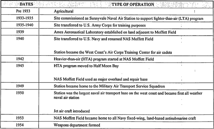
Table 1. History of Installation Operations
Environmental Baseline Survey
NASA Research Park Parcels
Moffett Federal Airfield, California
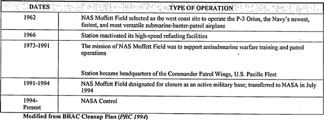
Table 2. Installation Restoration Program Sites
Environmental Baseline Survey
Initial Development Parcel 5
Moffett Federal Airfield, California
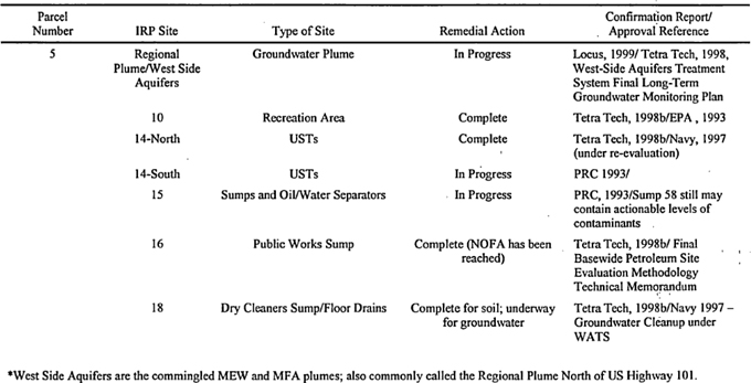
Table 3. Underground Storage Tank Status
Environmental Baseline Survey
NASA Research Park Parcel 5
Moffett Federal Airfield, California
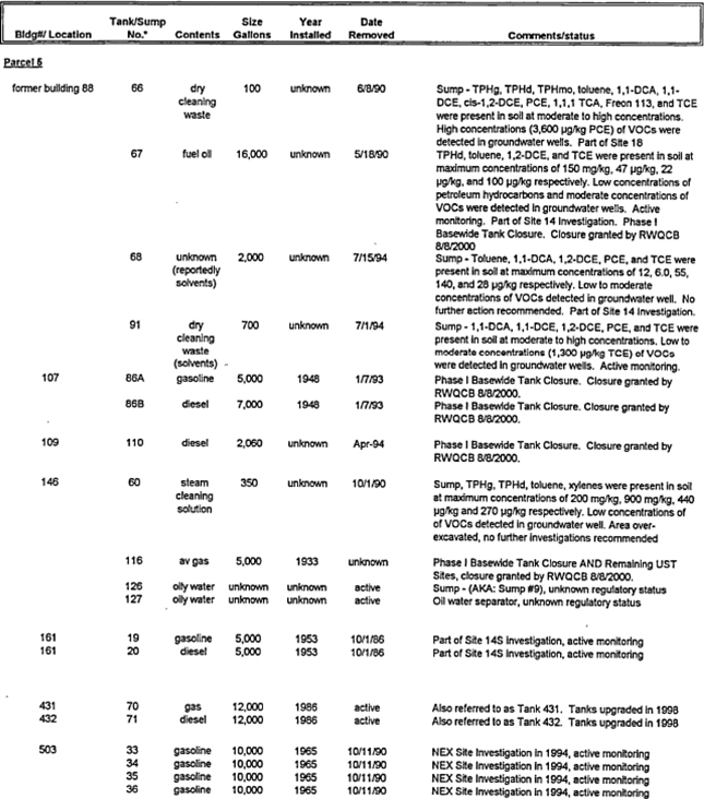
Table 3. Underground Storage Tank Status
Environmental Baseline Survey
NASA Research Park Parcel 5
Moffett Federal Airfield, California
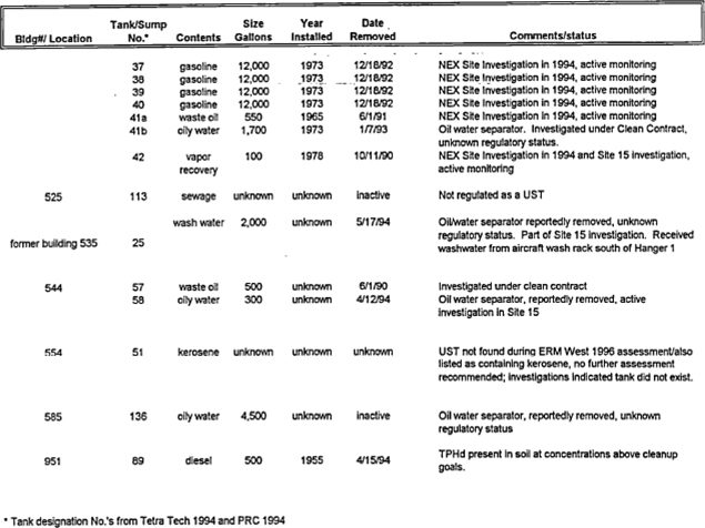
Table 4. Aboveground Storage Tank Status
Environmental Baseline Survey
NASA Research Park Parcel 5
Moffett Federal Airfield, California
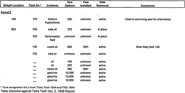
Table 5. Lead Based Paint Sampling Results
Environmental Baseline Survey
NASA Research Park Parcel 5
Moffett Federal Airfield, California
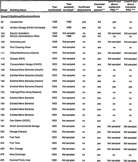
Table 5. Lead Based Paint Sampling Results
Environmental Baseline Survey
NASA Research Park Parcel 5
Moffett Federal Airfield, California
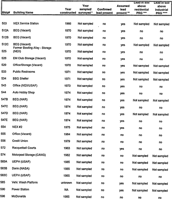
Table 5. Lead Based Paint Sampling Results
Environmental Baseline Survey
NASA Research Park Parcel 5
Moffett Federal Airfield, California
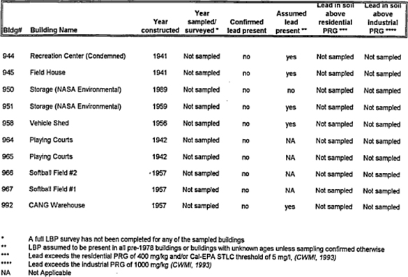
Table 6. Asbestos Survey/Sampling Results
Environmental Baseline Survey
NASA Research Park Parcel 5
Moffett Federal Airfield, California
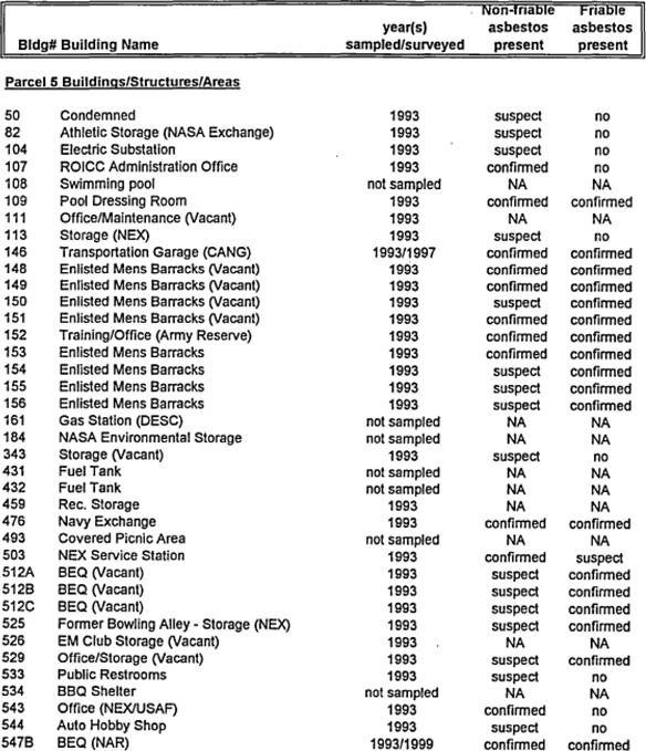
Table 6. Asbestos Survey/Sampling Results
Environmental Baseline Survey
NASA Research Park Parcel 5
Moffett Federal Airfield, California
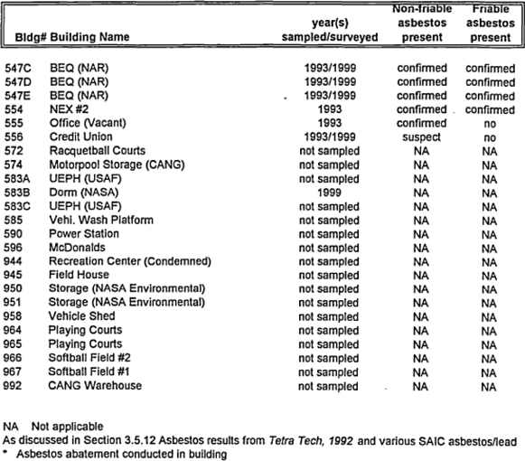
Table 7. PCB Impacted Transformer/Capacitors
Environmental Baseline Survey
NASA Research Park Parcel 5
Moffett Federal Airfield, California
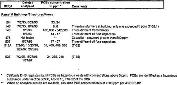
Table 8. Building List Summary
Environmental Baseline Survey
NASA Research Park Parcel 5
Moffett Federal Airfield, California
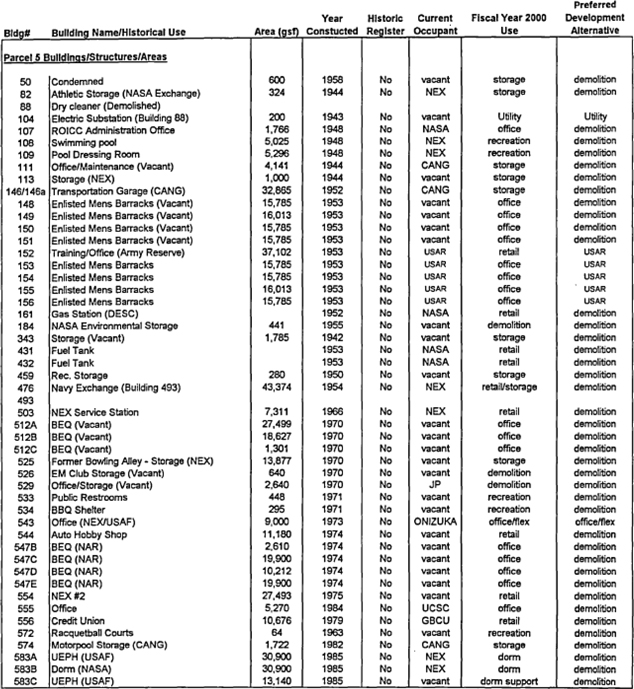
Table 8. Building List Summary
Environmental Baseline Survey
NASA Research Park Parcel 5
Moffett Federal Airfield, California
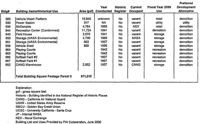
Table 9. Monitoring and Extraction Well Ownership and Total Depth
Environmental Baseline Survey
NASA Research Park Parcel 5
Moffett Federal Airfield, California
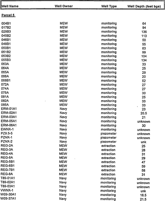
Table 9. Monitoring and Extraction Well Ownership and Total Depth
Environmental Baseline Survey
NASA Research Park Parcel 5
Moffett Federal Airfield, California
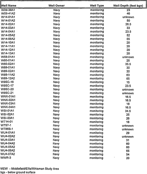
Table 10. Former (Prior to 1994) Hazardous Materials and Waste Locations
Environmental Baseline Survey
NASA Research Park Parcel 5
Moffett Federal Airfield, California
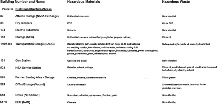
Table 10. Former (Prior to 1994) Hazardous Materials and Waste Locations
Environmental Baseline Survey
NASA Research Park Parcel 5
Moffett Federal Airfield, California

Table 11. Current (1994-2000) Hazardous Materials and Waste Locations
Environmental Baseline Survey
NASA Research Park Parcel 5
Moffett Federal Airfield, California
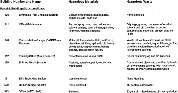
Table 11. Current (1994-2000) Hazardous Materials and Waste Locations
Environmental Baseline Survey
NASA Research Park Parcel 5
Moffett Federal Airfield, California
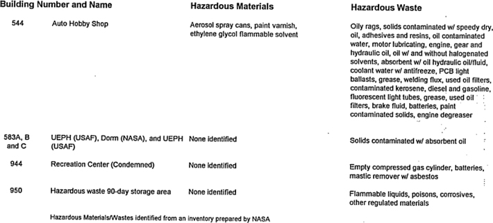
PLATES
APPENDIX A
PARCEL ENVIRONMENTAL SUMMARY REPORTS
| Administrative Draft — For Discussion Purposes Only | Appendix A | |
| Parcel 5 |
ENVIRONMENTAL SUMMARY REPORT
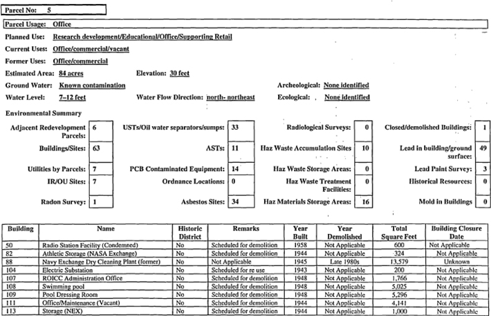
| Administrative Draft — For Discussion Purposes Only | Appendix A Parcel 5 |
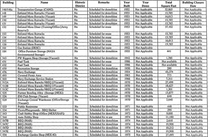
| Administrative Draft — For Discussion Purposes Only | Appendix A Parcel 5 |
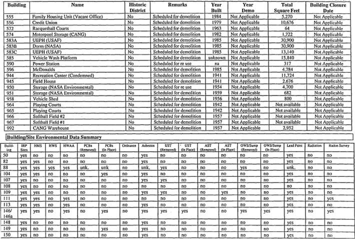
| Administrative Draft — For Discussion Purposes Only | Appendix A Parcel 5 |
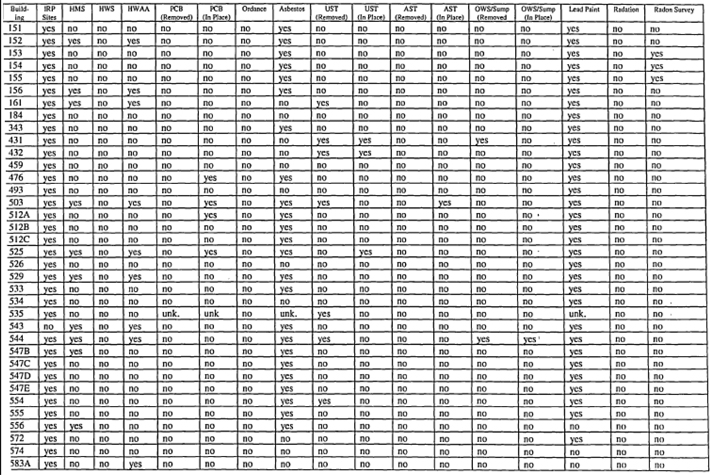
| Administrative Draft — For Discussion Purposes Only | Appendix A Parcel 5 |
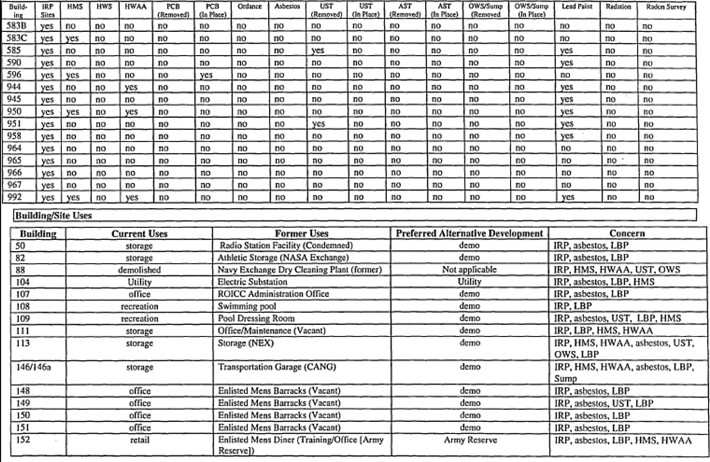
| Administrative Draft — For Discussion Purposes Only | Appendix A Parcel 5 |
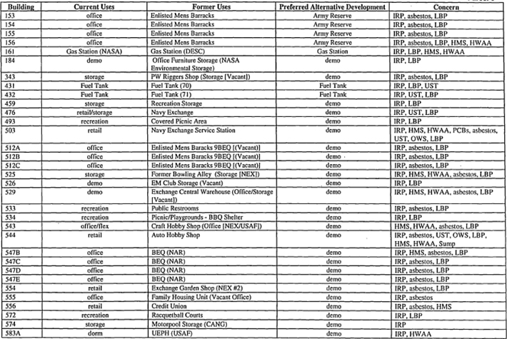
| Administrative Draft — For Discussion Purposes Only | Appendix A Parcel 5 |
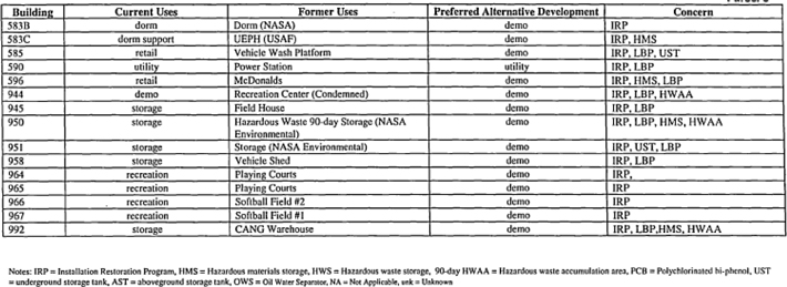
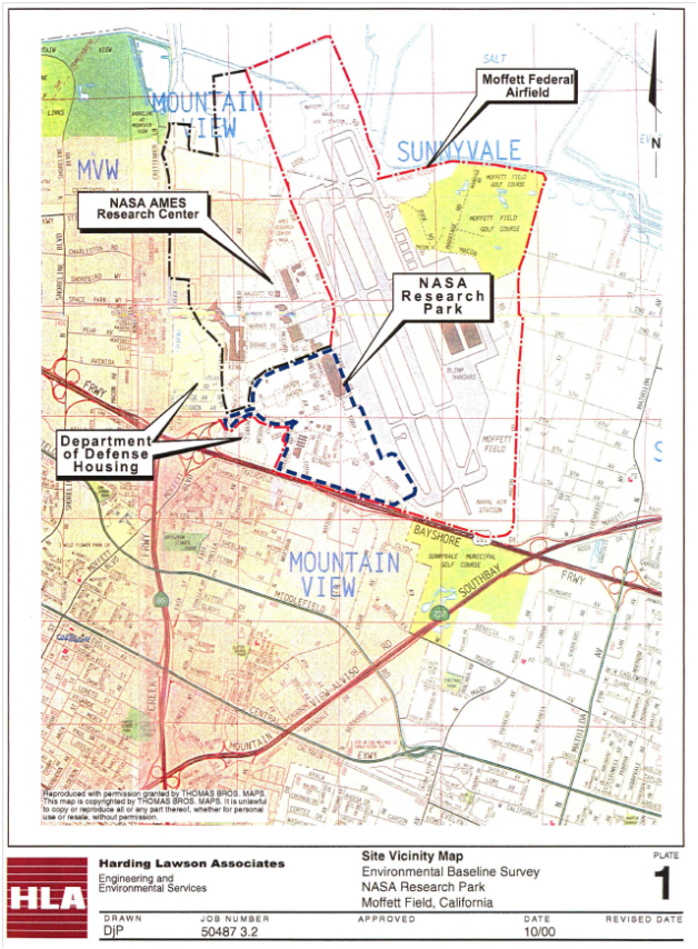
APPENDIX B
PLUME AND ALLOCATION MAPS
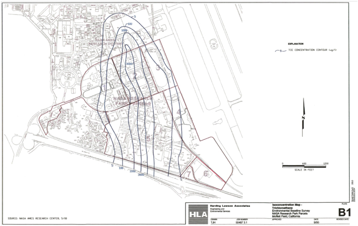
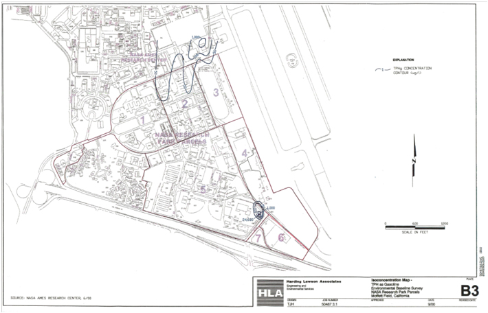
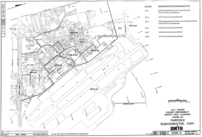
APPENDIX C
BURROWING OWL LOCATION MAP
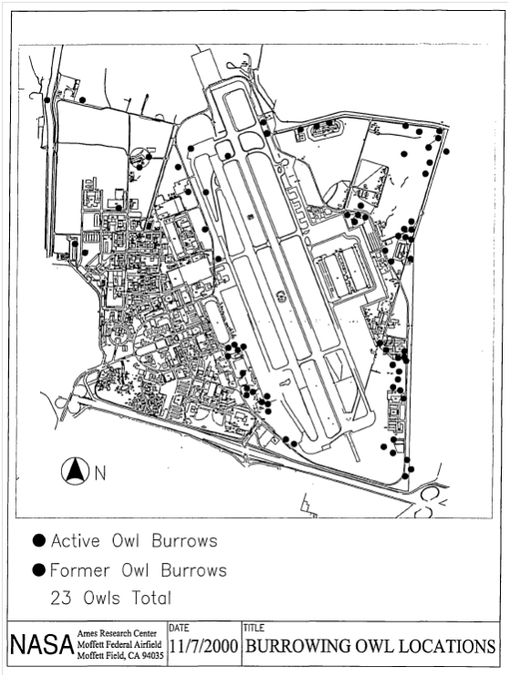
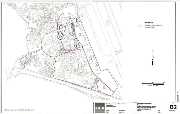
APPENDIX D
ARCHEOLOGICAL SENSITIVE AREAS
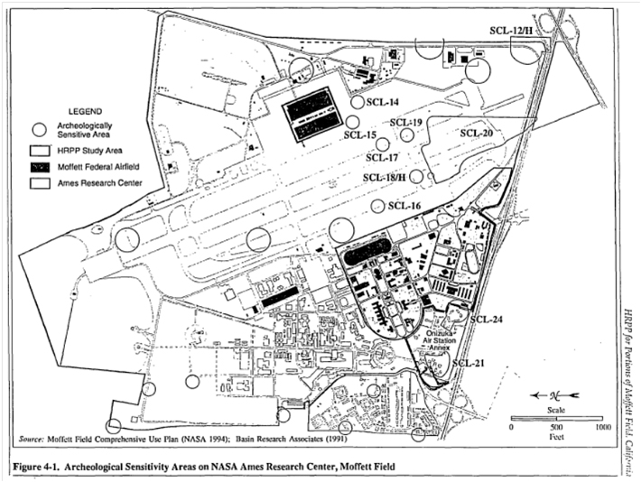
DISTRIBUTION
Environmental Baseline Survey
NASA Research Park Parcel 5
Moffett Federal Airfield
Moffett Field, California
December 28, 2000
| Copy No. 11 | ||
| Copies 1-2: | Sandy Olliges NASA Ames Research Center MS 218-1 Moffett Field, California 94035-1000 | |
| Copy 3: | Thomas H Anderson NASA/Ames Research Center MS 19-21 Moffett Field, California 94035-1000 | |
| Copy 4: | Joann Cola SFD-7-4 US Environmental Protection Agency 75 Hawthorne Street San Francisco, California 94105 | |
| Copy 5: | Roberta Blank- Superfund Division SFD-8-2 US Environmental Protection Agency 75 Hawthorne Street San Francisco, California 94105 | |
| Copy 6: | Joseph Chou California Regional Water Quality Control Board 1515 Clay Street Oakland, California 94612 | |
Harding ESE, Inc.
DISTRIBUTION
Environmental Baseline Survey
NASA Research Park Parcel 5
Moffett Federal Airfield
Moffett Field, California
December 28, 2000
| Copy 7: | Andrea Maclormare BRAC -Environmental Coordinator BRAC Operations, Code 00XX.XX 1230 Columbia Street Suite 1100 San Diego, California 92101 | |
| Copy 8: | Jim Boarer Locus Technologies 299 Fairchild Drive Mountain View, California 94043 | |
| Copies 9-11: | HLA Files | |
| Copy 12: | Corporate Copy | |
| Quality Control Reviewer |
|
|
| James C. Davies Consulting Principal |
Harding ESE, Inc.
CLOSURE PLAN NUMBER 5
INCLUDING BUILDINGS:
104, 107, 108, 109, 113, 476, 503, 525, 526, 529, 543, 554,
556, 596, and 944
NASA Ames Research Center
Moffett Field, California

Prepared By:
PAI/ISSi TEAM
Mail Stop 19-21
Moffett Field, California 94035-1000
Prepared for:
NASA Ames Research Center
Environmental Services Office
Mail Stop 218-1
Moffett Field, California 94035-1000
June 2001
TABLE OF CONTENTS
| Page | ||||||||
| 1.0 |
Introduction | 1 | ||||||
| 2.0 |
Historical Operations | 3 | ||||||
| 2.1 |
Former Building 88 - Site 18 (Navy Era) |
4 | ||||||
| 2.2 |
Building 104 (Navy Era) |
4 | ||||||
| 2.3 |
Building 107 (Navy Era) |
5 | ||||||
| 2.4 |
Building 108 (Navy Era) |
6 | ||||||
| 2.5 |
Building 109 (Navy Era) |
7 | ||||||
| 2.6 |
Building 113 (Navy Era) |
8 | ||||||
| 2.7 |
Building 476 (Navy Era) |
8 | ||||||
| 2.8 |
Building 503 (Navy Era) |
9 | ||||||
| 2.9 |
Building 525 (Navy Era) |
13 | ||||||
| 2.10 |
Building 526 (Navy Era) |
13 | ||||||
| 2.11 |
Building 529 (Navy Era) |
14 | ||||||
| 2.12 |
Building 543 (Navy Era) |
15 | ||||||
| 2.13 |
Building 554 (Navy Era) |
15 | ||||||
| 2.14 |
Building 556 (Navy Era) |
16 | ||||||
| 2.15 |
Building 585 (Navy Era) |
16 | ||||||
| 2.16 |
Building 596 (Navy Era) |
16 | ||||||
| 2.17 |
Building 944 (Navy Era) |
17 | ||||||
| 3.0 |
Site Reconnaissance | 18 | ||||||
| 4.0 |
Current Operations | 19 | ||||||
| 4.1 |
Building 104 (Post - Navy Era) |
19 | ||||||
| 4.2 |
Building 107 (Post - Navy Era) |
19 | ||||||
| 4.3 |
Building 108 (Post - Navy Era) |
19 | ||||||
| 4.4 |
Building 109 (Post - Navy Era) |
20 | ||||||
| 4.5 |
Building 113 (Post - Navy Era) |
20 | ||||||
| 4.6 |
Building 476 (Post - Navy Era) |
21 | ||||||
| 4.7 |
Building 503 (Post - Navy Era) |
21 | ||||||
| 4.8 |
Building 525 (Post - Navy Era) |
23 | ||||||
| 4.9 |
Building 526 (Post - Navy Era) |
23 | ||||||
| 4.10 |
Building 529 (Post - Navy Era) |
23 | ||||||
| 4.11 |
Building 543 (Post - Navy Era) |
24 | ||||||
| 4.12 |
Building 554 (Post - Navy Era) |
24 | ||||||
| 4.13 |
Building 556 (Post - Navy Era) |
24 | ||||||
| 4.14 |
Building 596 (Post - Navy Era) |
25 | ||||||
| 4.15 |
Building 944 (Post - Navy Era) |
25 | ||||||
i
TABLE OF CONTENTS (cont’d)
| Page | ||||||||
| 5.0 |
Existing Environmental Constraints |
26 | ||||||
| 5.1 |
Monitoring and Extraction Wells |
29 | ||||||
| 5.1.a |
Groundwater Conditions |
30 | ||||||
| 5.2 |
Lead Sampling Study of Surface Soils |
31 | ||||||
| 5.2.a |
Chemical Wste Management, INC. (CWMI) Surface Soil Lead Survey |
31 | ||||||
| 5.2.b |
Weston Inc., Lead Based Paint Investigation Report for NAS Moffeff Field, EPA Region IX |
33 | ||||||
| 5.3 |
MEW Regional Groundwater Remediation Program (RGRP) System |
34 | ||||||
| 5.4 |
Areas of Potential and Existing Contamination |
35 | ||||||
| 5.5 |
Removal of Areas of Existing Contamination |
35 | ||||||
| 5.5.a |
Site 14 |
36 | ||||||
| 5.5.b |
Site 15 |
36 | ||||||
| 5.5.c |
Site 18 |
36 | ||||||
| 5.5.d |
Building 104 |
36 | ||||||
| 5.5.e |
Building 107 |
36 | ||||||
| 5.5.f |
Building 503 |
37 | ||||||
| 5.5.g |
Building 525 |
37 | ||||||
| 5.5.h |
Building 529 |
37 | ||||||
| 5.5.i |
Building 543 |
37 | ||||||
| 5.5.j |
Building 556 |
38 | ||||||
| 5.6 |
Facility Sampling and Analysis |
38 | ||||||
| 5.6.a |
Site 14 |
38 | ||||||
| 5.6.b |
Site 15 |
38 | ||||||
| 5.5.c |
Site 18 |
39 | ||||||
| 5.6.d |
Building 104 |
39 | ||||||
| 5.6.e |
Building 107 |
39 | ||||||
| 5.6.f |
Building 503 |
39 | ||||||
| 5.6.g |
Building 525 |
39 | ||||||
| 5.6.h |
Building 529 |
39 | ||||||
| 5.6.i |
Building 543 |
39 | ||||||
| 5.6.j |
Building 556 |
39 | ||||||
| 6.0 |
Facility Closure Procedures |
40 | ||||||
| 6.1 |
Santa Clara County Requirements |
40 | ||||||
| 6.1.a |
Hazardous Materials Storage Closure |
40 | ||||||
| 6.2 |
Air Pollution Control Requirements Associated w/Site Closure |
40 | ||||||
| 6.3 |
Industrial Wastewater Requirements Associated w/Site Closure |
40 | ||||||
| 6.4 |
Polychlorinated Biphenyls (PCB) |
41 | ||||||
| 6.5 |
Burrowing Owls |
41 | ||||||
| 6.6 |
Storm Water Management during Site Closure |
42 | ||||||
| 6.6.a |
The Navy Era’s Former Illicit Connection Program |
42 | ||||||
ii
TABLE OF CONTENTS (cont’d)
| Page | ||||||||
| 6.6.b |
Best Management Practices |
42 | ||||||
| 6.6.c |
Ames’ Storm Water Pollution Prevention Plan (SWPPP) |
43 | ||||||
| 6.6.d |
New NPDES Requirements for Construction |
43 | ||||||
| 6.7 |
Spill Prevention Control and Countermeasures (SPCC) |
44 | ||||||
| 6.8 |
National Historic Preservation Act |
44 | ||||||
| 7.0 |
Future Environmental Constraints |
44 | ||||||
| 7.1 |
Monitoring and Extraction Wells |
45 | ||||||
| 7.2 |
MEW Regional Groundwater Remediation Program (RGRP) System |
45 | ||||||
| 7.3 |
Areas of Potential and Existing Contamination |
46 | ||||||
| 8.0 |
Environmental Requirements for Facility Construction |
46 | ||||||
| 8.1 |
Hazardous Materials Storage Installation |
46 | ||||||
| 8.1.a |
Tank Installation Requirements |
47 | ||||||
| 8.2 |
Air Pollution Control Installation |
47 | ||||||
| 8.3 |
Industrial Wastewater Requirements Associate w/Site Installation |
48 | ||||||
| 8.4 |
Borrowing Owl Requirements Associated with Site Installation |
48 | ||||||
| 8.5 |
Storm Water Management Requirements Associated with Site Installation |
48 | ||||||
| 8.6 |
Spill Prevention Control and Countermeasures (SPCC) Associated with Site Installation |
49 | ||||||
| 8.7 |
Archeological Resources |
49 | ||||||
| 8.8 |
Unexpected Discovery Plan |
49 | ||||||
LIST OF TABLES
| Table 1 Building Occupants |
3 | |||
| Table 2 Underground Storage Tanks Previously at Building 503 |
10 | |||
| Table 3 1984 HMIS for Building 503 |
12 | |||
| Table 4 Equipment List |
18 | |||
| Table 5 Groundwater Monitoring and Extraction Wells |
29 | |||
| Table 6 Monitoring Well COC’s |
31 | |||
| Table 7 Lead Concentration and Recommendations (CWMI Survey) |
32 | |||
| Table 8 Results from XRF Lead Based Paint Survey of Structures |
34 | |||
| Table 9 Predicted Laboratory Lead Concentrations |
34 | |||
| Table 10 Surface Sampling at Buildings 104, 525, 529, 543, and 556 |
38 | |||
iii
TABLE OF CONTENTS (cont’d)
LIST OF APPENDICES
| Appendix A |
Fact Sheet - NASA Ames Development Plan | |
| Appendix B |
Santa Clara County Storage Permits and Inspection Reports, Navy Era | |
| Appendix C |
BIER Reports | |
| Appendix D |
Historic Photographs, Navy Era | |
| Appendix E |
Current Photographs, Post Navy Era | |
| Appendix F |
Santa Clara County Permits and Inspections, Post Navy Era | |
| Appendix G |
Santa Clara County Facility Closure Guidelines | |
| Appendix H |
Table A-1 Identified Illicit Discharges, Discharges Requiring Additional Investigation and Potable Water Discharges | |
| Appendix I |
Storm Water Best Management Practices | |
| Appendix J |
Department of Parks and Recreation (DPR) 523 Forms | |
| Appendix K |
Santa Clara County Permit Applications | |
| Appendix L |
Santa Clara County Underground/Aboveground Storage Installation Guidelines | |
LIST OF FIGURES
| Figure 1 |
Site Map | |
| Figure 2 |
Proposed Land Use Plan | |
| Figure 3 |
Proposed Land Use Plan | |
| Figure 4 |
Monitoring and Extraction Wells | |
| Figure 5 |
Proposed Soil Sample Locations | |
| Figure 6 |
Borrowing Owl Locations | |
| Figure 7 |
Shenandoah Plaza Historic District | |
| Figure 8 |
Archeological Sensitive Areas | |
iv
TABLE OF CONTENTS (cont’d)
LIST OF ACRONYMS
| Ames |
NASA Ames Research Center | |
| BAAQMD |
Bay Area Air Quality Management District | |
| bgs |
below ground surface | |
| BTEX |
Benzene, Toluene, Ethylbenzene and Xylenes | |
| CANG |
California Air National Guard | |
| CERCLA |
Comprehensive Environmental Response Compensation and Liability Act | |
| CFC |
Chlorofluorocarbon | |
| CLEAN |
Comprehensive Long-Term Environmental Action Navy | |
| CUP |
Moffett Field Comprehensive Use Plan | |
| DCE |
Dichloroethene | |
| DPR |
Department of Parks and Recreation | |
| EA |
Environmental Assessment | |
| EOD |
87th Explosive Ordnance Division | |
| EPA |
Environmental Protection Agency | |
| IS |
Invisible Studios | |
| MEW |
Middlefield-Ellis-Whisman | |
| Mg/kg |
Milligrams per kilogram | |
| Mg/1 |
Milligrams per liter | |
| MTBE |
Methyl Tert-Butyl Ether | |
| NEPA |
National Environmental Policy Act | |
| NRP |
NASA Research Park | |
| OSHA |
Occupational Safety and Health Administration | |
| PCB |
Polychlorinated Biphenyl | |
| POTW |
Publicly Owned Treatment Works | |
| PP |
Priority Pollutant | |
| ppm |
parts per million | |
| PRG |
Preliminary Remediation Goal | |
| R&D |
Research and Development | |
| RGRP |
Regional Groundwater Remediation Program | |
| RWQCB |
Regional Water Quality Control Board | |
| RIST |
Recirculating In-Situ Treatment System | |
| SCVWD |
Santa Clara Valley Water District | |
| SPCC |
Spill Prevention Control and Countermeasures | |
| SWPP |
Storm Water Pollution Prevention | |
| SVOC |
Semi Volatile Organic Compound | |
| TCE |
Trichloroethylene | |
| TOG |
Total Oil and Grease | |
| TPHg |
Total Petroleum Hydrocarbons as gasoline | |
| TPHjp5 |
Total Petroleum Hydrocarbons as JP5 | |
| TPHmo |
Total Petroleum Hydrocarbons as motor oil | |
| UST |
Underground Storage Tank | |
| VOC |
Volatile Organic Compound |
v
| 1.0 | INTRODUCTION |
This closure plan describes procedures to ensure that the Buildings 104, 107, 108, 109, 113, 476, 503, 525, 526, 529, 543, 554, 556, 596, and 944 will be closed in a manner protective of human health and the environment. These buildings are referred to as the site for the purposes of this plan. The primary objective of this plan is the identification of actions to be taken prior to building closure. The site will be redeveloped as a result of the proposed University Reserve in the proposed NASA Research Park. (See Figure 1).
This plan specifically addresses the requirements and procedures for demolition of Buildings 104, 107, 108, 109, 113, 476, 503, 525, 526, 529, 543, 554, 556, 596, and 944 and other subsurface structures such as ground water monitoring and extraction wells. The plan also discusses some environmental requirements for the new construction associated with the University Reserve. See Figures 2 and 3 entitled “Proposed Land Use Plan”. The area depicted as the University Reserve includes the site addressed in this document, as well as other buildings and recreational areas that are evaluated in other plans.
Ames is a federal facility located at Moffett Field, California. Ames comprises 440 acres of the 1,857-acre Moffett Field site. Moffett Federal Airfield (formerly Naval Air Station Moffett Field) and Army Corp of Engineering Housing occupy the remainder of Moffett Field.
This plan includes facility descriptions and portrays hazardous materials handling operations. The environmental actions required for closure of facilities whose operations use and store hazardous materials have been highlighted. Hazardous materials storage areas are identified. Equipment and facilities requiring closure procedures for storage areas, equipment, structures, and facilities prior to demolition are listed.
A list of equipment associated with the hazardous materials handling operations such as air compressors, fume hoods, parts washers, degreasing units, paint booths, refrigerant recycling equipment, blasting machines, and oil filter draining equipment are included in the plan. The plan lists equipment that may generate contamination such as motor vehicle and truck washing units when identified. Additional surface and subsurface investigations are also described in the plan, if needed.
The plan also identifies infrastructure that may contain hazardous materials such as chlorofluorocarbons in air conditioners and PCBs in electrical equipment. Subsurface and aboveground structures used to treat contaminated groundwater or industrial wastewater and oil water separators are also discussed when present.
In 1991, the Federal Base Closure and Realignment Commission decided to close Moffett Field Naval Air Station. Subsequently, the U.S. Department of Defense transferred stewardship of the property to NASA. NASA took over administration of Moffett Field in 1994 as a “Closed Federal Facility”. The reuse of Moffett Field was originally addressed in the Moffett Field Comprehensive Use Plan (CUP) and its associated Environmental Assessment (EA), which resulted in a Finding of No Significant Impact in 1994. The CUP designated Moffett Field a shared use facility that would house Federal Agencies and their contractors. Federal Agencies who have land use agreements with Ames at Moffett Field are referred to as Resident Agencies and include the California Air National Guard (CANG), the Army Reserves, and the Federal Emergency Management Agency.
1
NASA is currently planning to develop a world-class, shared-used educational and Research & Development (R&D) campus focused on astrobiology, life sciences, space sciences, nanotechnology, biotechnology, information technology, and aeronautics. This project is referred to as the NASA Research Park (NRP). The NRP is one component of the proposed NASA Ames Development Plan, which outlines planned development at Moffett Field in four areas: NRP, Ames Campus, Bay View, and Eastside/Airfield. Appendix A contains the “Fact Sheet” describing the Environmental Baseline Survey (EBS) for Parcel 5.
As a result of the NRP, including the University Reserve, many existing facilities on Moffett Field will require demolition. Buildings 104, 107, 108, 109, 113, 476, 503, 525, 526, 529, 543; 554, 556, 596, and 944 will all have to be demolished in order for this proposed project to go forward.
This Closure Plan will be distributed to the Environmental Protection Agency (EPA), the Regional Water Quality Control Board (RWQCB), the Santa Clara County Health Department, prospective NASA Partners, the Navy, and the Middlefield-Ellis-Whisman (MEW) companies since the site overlies the regional groundwater plume.
Redevelopment activities could impact Navy Installation Restoration Program sites and groundwater monitoring wells, and the MEW Regional Groundwater Remediation Program (RGRP), treatment system piping, groundwater extraction Wells, and groundwater monitoring wells.
2
| 2.0 | HISTORICAL OPERATIONS |
This section describes the historical use of the site. Historically the Navy occupied the site. Table 1 reflects the historic and current building occupants.
TABLE 1
BUILDING OCCUPANTS
| Building |
Date Built |
Historic Occupants |
Current Occupant | |||
| 104 |
1943 / 90 | Navy | NASA | |||
| 107 |
1948 | Navy | Navy ROICC Office | |||
| 108 |
1980 | Navy | Navy Exchange | |||
| 109 |
1948 | Navy | Navy Exchange | |||
| 113 |
1944/1990 | Navy Exchange | Navy Exchange | |||
| 476 |
1964 | Navy Exchange | Navy Exchange | |||
| 503 |
1966 | Navy Exchange | Navy Exchange | |||
| 525 |
1970 | Navy Exchange | Onizuka | |||
| 526 |
1976 | Navy Exchange | Onizuka | |||
| 529 |
1968 | Navy Exchange | Navy Exchange | |||
| 543 |
1973 | Navy | Onizuka | |||
| 554 |
1975 | Navy Exchange | Navy Exchange | |||
| 556 |
1979 | Credit Union | Credit Union | |||
| 596 |
1985 | McDonalds | McDonalds | |||
| 944 |
1941 | Navy● | Onizuka |
Several documents were reviewed to assess the historical presence of hazardous materials and potential pathways for surface and subsurface contamination in and around Buildings 104, 107, 108, 109, 113, 476, 503, 525, 526, 529, 543, 554, 556, 596, and 944. These documents include:
| • | The 50th Anniversary of NAS Moffett Field, published by Specialty Graphics, 1983. |
| • | Naval Energy and Environmental Support Activity (NEESA). 1984, “Initial Assessment Study of Naval Air Station, Moffett Field, California. March |
| • | Final Report Industrial Waste Engineering Study, Naval Air Station, Moffett Field, ERM-West/AQA Resources, April 1986. |
| • | NAS Moffett Field California, published by Specialty Graphics, 1984 and 1988. |
| • | Moffett Federal Airfield Building List, NASA Ames Research Center, January 1998. |
| • | BIER database reports — 1992 through 1994. |
| • | Naval Air Station Moffett Field, Storm Water Pollution Prevention Plan, PRC Environmental Management, Inc., 1992. |
| • | Draft Report of Findings, Phase 1 Site Assessments, Area 2, Chemical Waste Management, Inc., April 1993. |
| • | The Interim Operating Permits for NAS Moffett Field issued on 1 July 1993 and 15 January 1994 by the City of Sunnyvale. |
| • | City of Sunnyvale Industrial Wastewater Discharge Permit Application, NASA Ames Research Center, June 2000. |
| • | Naval Air Station Moffett Field, Surface Soil Lead Survey, CWMI, October 1993. |
3
| • | EPA Region IX Lead Based Paint Investigation Report For NAS Moffett Field, Roy F. Weston, Inc., October 1998 |
| • | Building 45, 250 and 950 Phase II Site Assessment Naval Air Station Moffett Field, CA, Chemical Waste Management, Inc., May 1994. |
| • | Building 555 Assessment, including Buildings 107, 108, 109, 501, 555 and 566, Boeing Aerospace Operations, Inc., April 1994. |
A record search was conducted at the Santa Clara County of the Navy’s record using the privileges set forth in the “Freedom of Information Act”. These records were reviewed for this plan and are included in this plan. Appendix B contains copies of the hazardous materials storage permits and other related documentation such as inspection results.
Appendix C contains the Building Inventory Environmental Report (BIER) for the buildings that were inspected as part of the Moffett Development Project in the 1992 to 1994 timeframe and include Buildings 104, 107, 108, 109, 113, 476, 503, 525, 526, 529, 543, 554, 556, 596, and 944. The BIER reports include summaries of inspections and summaries of recommendations made by staff of the Ames Environmental Services Office and other Ames’ consultants. The historical sections of this plan are titled “Navy Era” to indicate the period of Navy operations prior to transfer to NASA.
| 2.1 | Former Building 88 — Site 18 (Navy Era) |
Before it was closed in 1987, Building 88 served as NAS Moffett Field’s laundry and dry cleaning facility. This building and its associated features were demolished by the Navy in 1994 and were remediated. Site 18 is discussed in Section 5.5.
| 2.2 | Building 104 (Navy Era) |
Building 104 is a 200 square foot building constructed in 1943. The construction type was classified as permanent. The building condition was considered standard and was constructed of concrete and wood. The Navy used this facility for operations/maintenance. The facility description is an impound lot for the 12 KVA electrical distribution substation. The substation is located on a covered pad. This facility is enclosed in a fenced area. A small building in the fenced area houses batteries to activate switches in case of power outages.
Ames Environmental Contractors’ Uribe & Associates (U&A) inspected Building 104 on 15 April 1993. Their inspection results are documented in the Report of Findings, Phase 1 Building Assessments, Area 2.An excerpt of this report follows.
Building 104, an electrical distribution substation built in 1943, has an area of approximately 2500 sq. ft. Electrical equipment is situated in a fenced yard. There are two structures; one is a workshop, the other is a battery room. (See Appendix D, Photograph 1). Construction is concrete and steel; condition is reported to be standard. The subject site is located in Operable Unit 4 for groundwater.
4
This facility is a 12Kv substation and has four transformers; two are labeled as containing PCBs. There are also three capacitors, two of which contain PCBs. (See Appendix D, Photograph 2). No leaks were observed. Acid containing lead batteries were stored as a backup power source.
The soil and/or concrete beneath the transformers and capacitors should be sampled for PCBs. The battery storage room and workshop should also be sampled for metals and semi-volatile organics. There is potential surface and subsurface contamination at this site that should be further evaluated.
Based on a review of the Navy’s Industrial Wastewater permits, no industrial wastewater generating activities were conducted at Building 104 in either the 1993 or 1994 permits. A review of the Navy’s Industrial Waste Engineering Study’s Final Report indicates no industrial wastewater generating activities were conducted at Building 104.
Records from the BAAQMD indicate there were no air pollution sources associated with this building.
| 2.3 | Building 107 (Navy Era) |
Ames Environmental Contractors’ Boeing Aerospace Operations, Inc. inspected Building 107 on 29 January 1993. Their results were documented in the Report of Findings, Building 555 Assessment including Buildings 107, 108, 109, 501, 555, and 566. An excerpt of this report follows.
Review of Former Buildings
Building 107 was constructed’ in 1948 and was designated as administrative for use by the Navy as Security Administration and for use by the ROICC. On 29 January 1993 the MFDP environmental staff assessed Building 107. No storage or use of hazardous materials was associated with Building 107.
Based on conversations with Assistant Fire Chief Robert Eaton, Mr. Rick Cey of the Navy’s Safety Office and John Shakelton of Moffett Field Public Affairs Office, Building 107 was originally used as a gasoline station. It is estimated that Building 107 served as a gasoline station from 1948 to the early 1950’s. Remnants of islands that served as air and water dispensers were observed. These islands were located against the north side of Building 107 facing Wescoat Road.
There were two 4,000 gallon underground storage tanks (USTs), Tanks 86A and 86B located on the west side of the building. The tanks were removed from the site in January 1993, under a permit issued by Santa Clara County, and the area had been covered with soil. The installation date of the USTs #86A and #86B is unknown. Based on the type of tank construction (single walled steel), it is possible that the USTs were the original gasoline fueling station tanks from 1948.
On 7 January 1993, four soil samples were collected and two water samples were collected from the excavation pit. The samples were received by Sequoia Analytical on 8 January 1993 and analytical results reported on 19 January 1993. Analytical results from the soil samples collected
5
during closure of tanks 86A and 86B reported non detect (ND) for Benzene, Toluene, Ethyl benzene and total Xylenes (BTEX) and purgeable hydrocarbons (total petroleum hydrocarbons as gasoline). There were detectable concentrations of BTEX and purgeable hydrocarbons in the groundwater samples analyzed. The BTEX and purgeable hydrocarbons were reported in micrograms per liter (ug/L) as listed. The maximum contaminant levels (MCLs) are set by the California and Environmental Protection Agency (EPA) and are the concentrations of chemicals that are not to be exceeded in water supplied to the public. The MCLs are also reported in ug/L for ease of comparison.
| Chemical Name |
Tank 86A | Tank 86B | MCL | |||
| Benzene |
0.75 | 160 | 1.0 | |||
| Toluene |
2.1 | 780 | not available | |||
| Ethylbenzene |
ND | 130 | 680 | |||
| Xylene |
4.3 | 1400 | 1750 | |||
| Purgeable hydrocarbons |
ND | 7300 | not available |
Analysis for lead concentrations in the water reported 1.7 milligrams per liter (mg/L) of lead at the tank 86A sample and 1.3 mg/L of lead at tank 86B sample. The amounts of lead detected exceeded the MCL of 0.05 mg/L and also exceeded the State of California’s Applied Action Levels (AAL) of 10 ug/L for freshwater species and 4 ug/L for saltwater species. The AAL’s were developed based solely on health effects without consideration for technical feasibility or economic factors.
Based on a review of the Navy’s Industrial Wastewater permits, no industrial wastewater generating activities were conducted at Building 107 in either the 1993 or 1994 permits. A review of the Navy’s Industrial Waste Engineering Study’s Final Report indicated no industrial wastewater generating activities were conducted at Building 107.
Records from the BAAQMD indicate there were no air pollution sources associated with this building.
| 2.4 | Building 108 (Navy Era) |
Ames’ Environmental Contractors Boeing Aerospace Operations, Inc. inspected Building 108 on 29 January 1993. Their results were documented in the Report of Findings, Building 555 Assessment including Buildings 107, 108, 109, 501, 555, and 566. An excerpt of this report follows.
Building 108 was the swimming pool. An aerial photograph review reveals that the swimming pool was built about 1956.
Since 1956 the location and activities of the swimming pool and the Physical Conditioning/Dress Facility have essentially remained unchanged over the years. Sometime during 1970, the swimming pool was enclosed in an inflatable dome cover. The swimming pool was uncovered in 1971, covered again in 1972, and the dome cover was finally removed in 1973. It is not apparent if chemicals were historically stored on-site to maintain the swimming pool, and if so, the location of chemical storage is unknown.
6
The Navy corrected the illicit piping connection to the storm drain at the swimming pool (Building 108).
On 17 February 1994 the Navy commenced tank removal activities for tank #110. Tank #110 was located on the north side of Building 108. Tank #110 was a 2,060-gallon, steel, single-walled tank formerly used for diesel storage for a boiler. The Navy had listed tank #110 as inactive.
Building 108 did not have a boiler associated with it. All heating requirements were provided by a heat exchanger located in Building 109 (see Section 2.4 Building 109) that operated using steam heat provided by Building 10.
Based on a review of the Navy’s Industrial Wastewater permits, no industrial wastewater generating activities were conducted at Building 108 in either the 1993 or 1994 permits. A review of the Navy’s Industrial Waste Engineering Study’s Final Report indicates no industrial wastewater generating activities were conducted at Building 108.
Records from the BAAQMD indicate there were no air pollution sources associated with this building. Specifically the Navy’s air permit records did not show an air pollution permit of any boiler or for Tank #110 that is associated with this building.
| 2.5 | Building 109 (Navy Era) |
Ames Environmental Contractors’ Boeing Aerospace Operations, Inc. inspected Building 109 on 29 January 1993. Their results were documented in the Report of Findings, Building 555 Assessment including Buildings 107, 108, 109, 501, 555, and 566. An excerpt of this report follows.
Building 109 is the Physical Conditioning/Dress Facility. Building 109 was constructed in 1948.
Based on a review of historic records including the Navy’s Industrial Wastewater permits, Building 109 discharged 5 gallons per day of Heat exchanger condensate to the sanitary sewer. A review of the Navy’s Industrial Waste Engineering Study’s Final Report indicates no industrial wastewater generating activities were conducted at Building 109, although the wastewater permits indicate that there was discharge of Heat Exchanger condensate.
Based on a review of historic records including records from the BAAQMD indicate there were no air pollution sources associated with this building.
Mr. Robert Holston, an inspector for Santa Clara County’s Hazardous Materials Compliance Division, conducted an inspection of Building 109 on 19 April 1994. Mr. Clint Fisher, of the Navy, accompanied him on this inspection. No hazardous materials storage issues were observed. He noted that the US Air Force was going to assume operation of the pool facility. The 10 October 1992 inspection reported the following four non-compliance items. Provide secondary containment for acid and chlorine storage. Provide spill containment materials and personal protective equipment and make it readily available in case of a spill. All hazardous material handlers must have appropriate training. Provide documentation. Initiate a weekly inspection program. Maintain documentation. The hazardous materials storage permits
7
document 350 gallons of corrosive materials. (See Appendix B). Mr. Holston conducted a closure inspection on 19 April 1994 the following was recorded. No storage issues outstanding. The U.S. Air Force to assume operation of this facility.
| 2.6 | Building 113 (Navy Era) |
Ames Environmental Contractors’ Uribe and Associates (U&A) inspected Building 113 on 15 April 1993. Their inspection results are documented in the Report of Findings, Phase I Building Assessments, Area 2. An excerpt of this report follows.
A review of aerial photographs suggested the present subject site was constructed after 1970 and before 1975. However, this location was formerly occupied by a pre-existing structure, which was razed before 1970, based on aerial photographs and building diagrams. The first structure was constructed in 1944, according to historical information and was present until at least 1968 (aerial photograph). Construction is concrete and steel; condition is reported as marginal (Proposed Assignments Database, 1993). Present use is for operations and maintenance. Building materials for concession booths are reportedly stored here (Kerr, 1993).
The facility drawing for Building 525 indicated the previous building at this location was used as a welding shop; a drawing was not available for the existing building. The subject site is part of Operable Unit 4 for groundwater.
The yard and building were full of junk furniture, empty 55-gallon drums (previous contents unknown), pipes, fencing, firewood, ladders, swimming pool equipment and tires. Some hazardous materials were observed on a pallet, including various cleaners (see Appendix D, Photograph 3). An unidentified gas cylinder and a propane cylinder were also noted. Hazardous waste was not evident. A minor amount of staining was observed on the accessible concrete in the storage yard. Transformer T-35 was located west of the building, within the fenced yard, and was identified to contain PCBs. Ames’ records indicate that this transformer is associated with Building 525 (see Section 2.9). No leakage of fluid from the transformer was evident.
Based on a review of the Navy’s Industrial Wastewater permits, no industrial wastewater generating activities were conducted at Building 113 in either the 1993 or 1994 permits. A review of the Navy’s Industrial Waste Engineering Study’s Final Report indicates no industrial wastewater generating activities were conducted at Building 113.
Records from the BAAQMD indicate there were no air pollution sources associated with this building.
| 2.7 | Building 476 (Navy Era) |
Building 476 was constructed in 1964 and was used by the Navy Exchange for administrative purposes as a store and as a cafeteria. The construction type was classified as permanent and is of standard construction. The building is constructed of concrete and steel. The gross square footage is 43,374. Ames’ environmental staff did not inspect this building during realignment activities. The office space contained window type air conditioning units.
8
Based on a review of the Navy’s Industrial Wastewater permits, no industrial wastewater generating activities were conducted at Building 476 in either the 1993 or 1994 permits. A review of the Navy’s Industrial Waste Engineering Study’s Final Report indicates no industrial wastewater generating activities were conducted at Building 476.
Records from the BAAQMD indicate there were no air pollution sources associated with this building.
| 2.8 | Building 503 (Navy Era) |
Ames Environmental Contractors’ Uribe & Associates (U&A) inspected Building 503 on 15 April 1993. Their inspection results are documented in the Report of Findings, Phase 1 Building Assessments, Area 2. An excerpt of this report follows.
Building 503, identified as the Navy Exchange Service Station or NEX, was built in 1966, and has an area of 7,240 sq. ft. Construction is concrete and steel; condition is standard. According to the IAS (1984), the service station has been located here at Building 503 since 1967. The service station stored and dispensed fuel and performed automotive repairs and maintenance. (See Appendix D, Photographs 4 and 5).
Hazardous wastes reported to be generated and/or accumulated at the site included: auto fluids, used oil, solvents, brake shoes and dust which contains asbestos, metal cuttings from brake drums and discs, and batteries. Hazardous materials included auto fluids, cleaners, solvents, lubricants, hydraulic oil, batteries, brake shoes (IAS, 1984). The Hazmat storage area was reported to be fenced and roofed (IAS, 1984). Only sealed batteries were reported to be sold, no electrolyte was stored (Navy, 1991). Waste liquids including solvents, were disposed of with waste oil in a holding tank (no number given) located about 500 feet east of the building. This was probably Tank #41A. A local refining company (no reference given) periodically pumped the contents of the tank out. In the repair shop, parts were cleaned in a solvent bath, until 1978, when the station contracted for parts cleaning (IAS, 1984).
According to the waste minimization summary in City of Sunnyvale Permit Application (1991), deck drains were sealed on 16 September 1991. The sink remained open and drained to the sanitary sewer. Fuel was no longer dispensed, and only vehicle maintenance was provided. According to the letter from Steven Anschutz to Mark Malachowski, 31 May 1991, City of Sunnyvale, “all fuel was removed from the remaining USTs and adjoining pipelines.” A notice of Violation (NOV) for Total Toxic Organics (TTO) and Phenol concentrations in excess of the sewer discharge permit limitation was filed on 8 May 1991 by the City of Sunnyvale. The suspected source of the TTO was the fuel Underground Storage Tanks (USTs). There was a release of gasoline to the sanitary sewer in 1990 (Navy, 1990).
The subject site is Operable Unit 3 for soils (IRP sites 12 and 15) and Operable Unit 4 for groundwater. The only available information concerning soil samples collected during tank removal was for UST #41A. A soil sample contained: total petroleum hydrocarbons (TPH) as gasoline at 200 ppm, TPH as oil at 6400 ppm, total oil and grease (TOG) at 4500 ppm, and chlorinated hydrocarbons 1,1,1 trichloroethane at 3.7 ppb and PCE at 1.9 ppb; groundwater was reported in the tank pit (Quorum, 1991).
9
Building 503 was the site of numerous USTs and ASTs; the following tanks have all been removed (UST Database March, 1993). Table 2 lists the tanks that were previously located at Building 503.
Table 2
USTs Previously at Building 503
| UST# | Volume (gallons) |
Construction Content | Installation Date |
Removal Date | ||||||||
| #33 |
10,000 | steel | 1SUG | 1965 | 10 /11/ 90 | |||||||
| #34 |
10,000 | steel | 1SUG | 1965 | 10/11/90 | |||||||
| #35 |
10,000 | steel | 2RG | 1965 | 10/11/90 | |||||||
| #36 |
10,000 | steel | 2RG | 1965 | 10 /1/ 90 | |||||||
| #37 |
12,000 | fiberglass | 3UL | 1973 | 1/4/93 | |||||||
| #38 |
12,000 | fiberglass | 3UL | 1973 | 1/4/93 | |||||||
| #39 |
12,000 | fiberglass | 3UL | 1973 | 1/4/93 | |||||||
| #40 |
12,000 | fiberglass | 3UL | 1973 | 1/4/93 | |||||||
| #41A |
550 | steel | waste oil | 1965 | 6/1/91 | |||||||
| NOTES: | 1 SUG = Super Unleaded Gasoline |
2 RG = Regular Gasoline
3 UL = Unleaded Gasoline
The following tanks were also listed in the UST database:
| • | #41B a 1700-gallon concrete waste oil/water separator, removed 4 January 1993. |
| • | #42 sump a 100 gallon concrete condensed vapor sump, installed in 1978. This sump is included in IRP SITE 15 (IAS, 1984) and was part of the product delivery system. |
| • | Structure 535, an oil water separator which received waste water from former washrack 438, was located northeast of Building 503. |
The following ASTs were reported to be in place:
| • | # 108 a steel, 275 gallon lube oil storage tank. |
| • | # 109 unknown volume, used for transmission fluid storage. |
The building included a U-Haul rental office, an automotive shop and a brake shop.
Batteries were observed on a pallet, with no secondary containment. There were three floor jacks in the south wing and five in the main wing, each with an individual hydraulic system. Solvent was still used, in self contained bath units. Floor drains were plugged. Cuttings (metal fillings turned off of brake drums and discs with a lathe) from the brake shop were dumped near the western edge of the pavement. Hazardous material was stored, as reported, in a fenced, roofed storage area. However, no secondary containment was provided around the storage area. A surrounding curb was at the edge of the pavement. The shop floors were bare concrete. The surrounding pavement drained to unidentified drains (sewer or storm). ACMs and spent brake pads were observed to be contained in a 55 gallon drum, which was covered, secured, and labeled. A hot water heater was located in the men’s room, at the north end of the building.
10
Staining outside on the pavement is rust colored, dark grey and oily. According to the site drawings and field observations, Tank #41A the waste oil tank, was apparently located approximately 15 feet east of the building, not 500 feet east as reported.
No gasoline was stored or dispensed at the site. With the possible exception of the vapor recovery sump, all USTs have been removed. However, tank pit excavations were open during the site inspection and some piping remained at that time. The ASTs were located near the southwest corner of the building, next to the excavation for tank #4113 (the oil water separator), and did not have secondary containment. Waste oil was stored in drums and then placed in secondary containment tubs.
Discharge from oil water separator #4113 to the sanitary sewer was permitted (City of Sunnyvale, 1993). This separator was identified as a 1,000 gallon grease interceptor (should be 1,700 gallon) was removed. Structure 535, the oil water separator was not connected to nor did it appear to receive waste water from Building 503. Structure 535 was permitted.
Transformer #T-26 was located on the north side of the building. It was identified as Westinghouse model PAC 29073, 75KVA with 510,000 parts per million (ppm) PCB and appeared to be in good condition. The Navy inspector Mr. Danny Steinmete inspected transformer T-26 on 7 February 1992 the inspection record described the following condition of this equipment. The bushing was coated with melted tape/insulation. The condition of the equipment indicated that it needed to be shut down, inspected further, and cleaned up. Possible repairs might be needed based on a further inspection. This transformer was replaced with an air-filled transformer that does not contain any PCBs. This new transformer still retains the identification number T-26.
Soil and groundwater samples may have been collected during tank removal activities, but were not available (Chuck, 1993); these will have to be duplicated if they were not collected. At least one release, of gasoline, to the sanitary sewer has occurred. There is a possibility that some hazardous waste may have been disposed of in the various drains (storm and/or sanitary sewer). Pending the results of the soil and groundwater investigation performed to date, additional sampling may be required.
Significant suspect conditions were observed. Spills, releases or other activities resulting in contamination have occurred.
Based on a review of the Navy’s Industrial Wastewater permits, no industrial wastewater generating activities were conducted at Building 503 in either the 1993 or 1994 permits. However, Building 503 had a permitted operation on the Navy’s 1989 permit application. An oil/water separator in conjunction with the interior surface drains was being operated. The gallon per day discharged was reported as 444. A review of the Navy’s Industrial Waste Engineering Study’s Final Report indicates no industrial wastewater generating activities were conducted at Building 503. Industrial wastewater generation ceased in 1991 when all floor drains in the shop area were sealed. The associated oil/water separator was removed in 1993. Sinks are present for sanitation purposes only.
11
Records from the BAAQMD indicate there is one air pollution source — gasoline dispensing operation-permitted in 1996.
The Navy submitted a hazardous materials inventory (HMIS) to Santa Clara County for Building 503 on 10 July 1984. The inventory reported the following storage:
Table 3
1984 HMIS for Building 503
| Volume (gallons) |
Contents | Hazard Class | UN # | |||
| 20,000 |
premium gasoline | 3 | 1203 | |||
| 20,000 |
regular gasoline | 3 | 1203 | |||
| 48,000 |
unleaded gasoline | 3 | 1203 | |||
| 550 |
waste oil | 3 | 1270 | |||
| 100 |
gasoline vapor sump | 3 | 1270 |
Ms. Nicole Jakoby, an inspector for Santa Clara County’s Hazardous Materials Compliance Division, conducted an inspection of Building 503 on 10 October 1990. She observed the closure of the four (4) 10,000-gallon USTs. She noted that little corrosion or pitting and that no holes were observed in the tanks. Groundwater was observed in the bottom of the tank pits about 18” deep with floating product on its surface. Soil staining was observed all around the excavation. Six soil samples were collected all around the excavation. Six soil samples were collected around the sidewalls. Mr. Robert Holston conducted an inspection on 17 February 1993. This inspection reported the following two noncompliance items. Excavated soil not properly covered to prevent surface runoff. Two 20,000-fiberglass tank on paved area adjacent to the excavation were not properly barricaded to vehicles and citizens. This inspection requested that the conditions be mitigated with in 24 hours.
Mr. Robert Holston conducted an inspection on 2 May 1995. This inspection reported the following six non-compliance items. Submit a Hazardous Materials Business Plan. Secondary containment for transmission fluid, motor oil, grease, etc. is inadequate. Asphalt surface is not acceptable for containment. Provide proper containment for all materials. If structural changes are to be made the plans must be submitted for review. Provide secondary containment for the used battery storage. Initiate weekly inspections of the material and waste storage areas and document inspection results. Provide hazardous materials and waste management training for all employees handling hazardous substances. Secondary containment must be thoroughly cleaned up and investigated since possible soil contamination. Clean up as appropriate and submit a report to this office (Navy notified of this problem previously.)
Mr. Robert Holston conducted an inspection on 10 May 1995 and the Navy’s representative Mr. Clint Fisher was also present. This inspection reported the following. Previous inspection of Building 503 revealed heavy contamination of hazardous materials in the storage area located at the southwest corner of the building. Asphalt containment area showed oily staining throughout. The Navy has been previously instructed to initiate site investigation and take appropriate action to clean up the area. Instruction was given prior to Base Closure. Submit a site investigation plan and schedule of activities within 30 days. (See Appendix B).
12
| 2.9 | Building 525 (Navy Era) |
Ames Environmental Contractors’ Uribe & Associates (U&A) inspected Building 525 on 15 April 1993. Their inspection results are documented in the Report of Findings, Phase 1 Building Assessments, Area 2. An excerpt of this report follows.
The Bowling Alley was built in 1970, and has an area of 14,520 sq. ft. Construction is concrete and steel; condition is standard (Assignments, 1993). Hazardous materials storage included hand cleaner, electric cleaner, parts cleaner, rust penetrant, lacquer acrylic, motor oil, pine cleaner, ammonia cleaner, contact adhesive and scouring powder (IAS, 1984).
UST # 113 of unknown volume and steel construction, contained septic waste. The tanks were inactive (UST Database) and reportedly plugged with cement (Coe, 1993). The subject site was near Operable Unit 2 for soils and in Operable Unit 4 for groundwater.
Two floor drains were located in the kitchen. Waste grease was disposed of in a container in back of the building, northwest side. Transformer T-35 was located immediately east of the building, within the fenced yard of Building 113, and was identified to contain PCBs. No leakage of fluid from the transformer was evident. UST #113 was located on the northeast side of the building. Hazardous materials were kept in the maintenance room in the back of the building and in the janitor’s closet, and included cleaners and solvents. A locker for flammable materials was located outside, on the north side of the building.
The UST was exempted from a subsurface investigation as it was used as a septic tank. Soil samples should be collected from the locations shown next to the staining at the grease container and at the flammable materials locker.
Based on a review of the Navy’s Industrial Wastewater permits, no industrial wastewater generating activities were conducted at Building 525 in either the 1993 or 1994 permits. A review of the Navy’s Industrial Waste Engineering Study’s Final Report indicates no industrial wastewater generating activities were conducted at Building 525. The Building was closed in 1992 and at this time, the grease trap located in the kitchen area was disconnected and removed.
| 2.10 | Building 526 (Navy Era) |
Ames Environmental Contractors’ Uribe & Associates (U&A) inspected Building 526 on 15 April 1993. Their inspection results are documented in the Report of Findings, Phase 1 Building Assessments, Area 2. An excerpt of this report follows.
The Enlisted Men’s Club storage was built in 1970 and has an area of 540 sq. ft. Construction is concrete and steel; condition is reported standard. Current use is for storage of club furniture, i.e. tables and chairs, beer kegs from Building 244 (Kerr, 1993). The subject site was near Operable Unit 2 for soils and in Operable Unit 4 for groundwater.
No hazardous materials were observed. No sampling was recommended.
13
Suspect conditions were not observed. Spills, releases or other activities resulting in contamination have not been reported. Therefore, further building assessment does not seem warranted.
Based on a review of the Navy’s Industrial Wastewater permits, no industrial wastewater generating activities were conducted at Building 526 in either the 1993 or 1994 permits. A review of the Navy’s Industrial Waste Engineering Study’s Final Report indicates no industrial wastewater generating activities were conducted at Building 526.
Records from the BAAQMD indicate there were no air pollution sources associated with this building.
| 2.11 | Building 529 (Navy Era) |
Ames Environmental Contractors’ Uribe & Associates (U&A) inspected Building 529 on 15 April 1993. Their inspection results are documented in the Report of Findings, Phase 1 Building Assessments, Area 2. An excerpt of this report follows.
The Exchange Central Warehouse was built in 1970, and has an area of 2,640 sq. ft. Construction is concrete and steel; condition is reported to be marginal (Assignments, 1993). Historical use has not generated hazardous wastes, with the exception of a photofinishing lab (IAS, 1984). Initially, spent photoprocessing fluids were discharged to the sanitary sewer. Later this waste stream was collected for disposal as hazardous waste (Navy, 1991). The subject site was near Operable Unit 2 for soils and in Operable Unit 4 for groundwater.
The City of Sunnyvale issued a notice of violation (NOV) on 4 November 1991 for the silver content of the waste water discharge exceeding the permit limitation of 0.2 milligrams per liter (mg/L). A grab sample was collected from a sealed container of photoprocessing effluent at Building 529. The sample contained 3.2 mg/L silver. The Navy discontinued discharging effluent and closed floor drains as a corrective action to this NOV (Navy, 1991). However, discharge from the photo laboratory was still permitted (City of Sunnyvale, 1991).
The site was used for NEX services; television and household appliance rental. There was a fenced storage yard beside the building. A monitoring well is located in the storage yard. (See Appendix D, Photograph 6). According to site personnel, the photofinishing lab operated here from 1990 to about 1992. Photo developing equipment was no longer at the site. According to site personnel, spent chemicals were stored in a 50-gallon aboveground tank, and were hauled for disposal when necessary. The MSDS file for the building indicated refrigerants, paints, metal cleaner, glue, resin and flux. Also noted in the former photo lab were approximately 30 liters of Kodak bleach replenisher.
According to building personnel, Public Works was scheduled to pick up the current hazardous materials. No staining was observed; flooring looked original. Laundry chemicals were stored in two drums on top of a pallet in the storage yard.
Collection and analysis of soil samples were recommended next to the drums and elsewhere in the storage yard.
14
Based on a review of historic records including the Navy’s Industrial Wastewater permits, industrial wastewater generating activities were ended in 1992 at Building 529 and reported closed in the 1993 and 1994 permits. All associated photoprocessing equipment was removed at this time. However, Building 529 had a permitted operation on the Navy’s 1986 permit. The gallon per day discharged was reported as 10. A review of the Navy’s Industrial Waste Engineering Study’s Final Report indicates no industrial wastewater generating activities were conducted at Building 529.
Based on a review of historic records, the BAAQMD indicate there were no air pollution sources associated with this building.
| 2.12 | Building 543 (Navy Era) |
Ames Environmental Contractors’ Uribe & Associates (U&A) inspected building 543 on 16 April 1993. Their inspection results are documented in the Report of Findings, Phase 1 Building Assessments, Area 2. An excerpt of this report follows.
Building 543, the craft hobby shop, was built in 1973 and has an area of 9,000 sq. ft. (Assignments, 1993). Hazardous materials used at this site included Nova clean, adhesive, spray sealer, and Proclean. The subject site was near Operable Unit 2 for soils and in Operable Unit 4 for groundwater. The site was used as a craft hobby shop (Coe, 1993). Groundwater downgradient of the site was contaminated with chlorinated compounds, i.e. TCE (CLEAN).
Not all portions of the building were accessible. The primary use of the building appeared to be for hobby activities, including woodworking and painting (see Appendix E Photograph 7). Staining and paint were observed outside of the building. Paint in cans was observed inside the building.
Solvents were suspected to have been used at this site, in conjunction with paints. Soils adjacent to the pavement, south of the building, and possibly the pavement have been impacted by paint and probably have been impacted by solvents. Therefore, this site may be a source of soil and groundwater contamination and should be investigated accordingly.
Based on a review of the Navy’s Industrial Wastewater permits, no industrial wastewater generating activities were conducted at Building 543 in either the 1993 or 1994 permits. A review of the Navy’s Industrial Waste Engineering Study’s Final Report indicates no industrial wastewater generating activities were conducted at Building 543.
Records from the BAAQMD indicate there was one air pollution source - sawdust vacuum cleaning operation- permitted until 1993.
| 2.13 | Building 554 (Navy Era) |
Building 554 was constructed in 1975 and was used by the Navy Exchange for administrative purposes as the garden shop. The construction type was classified as semi-permanent and is of standard construction. The building is constructed of concrete and steel. The gross square footage is 27,493. Ames’ environmental staff did not inspect this building during realignment activities.
15
Building 554 was equipped with a transformer labeled T-36. This transformer was located on the East Side of this building. The style of this transformer was A13E5105DD, the serial number was 75F011017 and its size was 225 KVA. The manufacturer was Westinghouse.
Based on a review of the Navy’s Industrial Wastewater permits, no industrial wastewater generating activities were conducted at Building 554 in either the 1993 or 1994 permits. A review of the Navy’s Industrial Waste Engineering Study’s Final Report indicates no industrial wastewater generating activities were conducted at Building 554.
Records from the BAAQMD indicate there were no air pollution sources associated with this building.
| 2.14 | Building 556 (Navy Era) |
The Ames Environmental Contractors’ Uribe & Associates (U&A) inspected Building 556 on 16 April 1993. Their inspection results are documented in the Report of Findings, Phase 1 Building Assessments, Area 2. An excerpt of this report follows.
Building 556 was the Credit Union, which was built in 1979 and is a two-story building; surface area was not available. Construction is concrete/steel; condition is standard (Assignments, 1993). There were no suspect structures evident prior to building construction based on the review of the aerial photographs. The subject site was near Operable Unit 2 for soils and in Operable Unit 4 for groundwater.
The only hazardous materials observed were cleaning supplies, kept in a closet. Suspect conditions were not observed. Spills, releases or other activities resulting in contamination have not been reported. Therefore, further building assessment does not seem necessary.
Based on a review of the Navy’s Industrial Wastewater permits, no industrial wastewater generating activities were conducted at Building 556 in either the 1993 or 1994 permits. A review of the Navy’s Industrial Waste Engineering Study’s Final Report indicates no industrial wastewater generating activities were conducted at Building 556.
Records from the BAAQMD indicate there were no air pollution sources associated with this building.
| 2.15 | Building 585 (Navy Era) |
Building 585 is the Army Reserves’ truck wash. This truck wash was constructed after the Navy’s departure in 1994. This truck wash was included in Closure Plan 1 and addressed the transportation yard that is shared by the California Air National Guard and the Army Reserves. Therefore this feature will not be addressed in this plan.
| 2.16 | Building 596 (Navy Era) |
The Ames Environmental Contractors’ Uribe & Associates (U&A) inspected Building 596 on 16 April 1993. Their inspection results are documented in the Report of Findings, Phase 1 Building Assessments, Area 2. An excerpt of this report follows.
16
Building 596 was a McDonald’s’ restaurant, built in 1985, and had an area of 2,500 sq. ft. Construction was concrete and wood; condition was standard (Assignments, 1993). There was a permitted grease trap (City of Sunnyvale, 1993); information on hazardous materials/waste was not available. A non-PCB transformer (T-96) is present (Transformer Database, 1993). A site drawing was not available. The subject site was near Operable Unit 2 for soils and in Operable Unit 4 for groundwater.
The site was in immaculate condition. Hazardous materials, consisting of cleaners and degreasers, were stored on shelves in the back of the restaurant. The grease trap was cleaned on an as needed basis. Grease was properly disposed of in a waste grease bin, located in back of the building. No staining was observed. Suspect conditions were not observed.
Based on a review of the Navy’s Industrial Wastewater permits, Building 596 has a grease trap with a capacity of approximately 34 gallons. The Building discharged approximately 500 gallons per day from cleaning and sanitary sources as reported in the 1993 and 1994 permits. One, grease trap was listed with dimensions of 23” X 14” X 24”. The gallon per day discharged was reported as 1,570 in the Navy’s 1984 permit. A review of the Navy’s Industrial Waste Engineering Study’s Final Report indicated no other industrial wastewater generating activities were conducted at Building 596.
| 2.17 | Building 944 Formerly 244 (Navy Era) |
Records from the BAAQMD indicate there were no air pollution sources associated with this building.
Building 944 was constructed in 1941 and was used by the Navy’s Morale, Welfare, and Recreation (MWR) as the Enlisted Men’s Club/Parcheezi’s Pizza. The building is constructed of concrete and wood. The gross square footage is 11,724. The building is equipped with two HVAC units, one is located on the north side and the other is located on West Side.
Ames’ Environmental Contractors inspected Building 944 on 16 April 1993. Building 944 was equipped with fluorescent lighting. A grease trap was observed. Hazardous materials were observed consisting of ammonia, bleach, charcoal, charcoal lighter, solvents, cleaners, and soaps. Staining by hazardous materials and spills of hazardous materials were not observed. Several floor drains were observed (two inside the building and two outside the building). An underground storage tank (UST) was located near the southwest corner of the building as evidenced by the vent stack and fill port and was presumed to be UST Number 112. Mr. Don Chuck, formerly with the Navy, verbally indicated that the Navy conducted an investigation of the facility for the presence of the reported UST. Using a backhole the Navy dugup potholes to uncover the suspected UST, however a UST was not identified. Based on the results of this field investigation it was reported that a tank did not exist at this location.
Based on a review of the Navy’s Industrial Wastewater permits, no industrial wastewater generating activities were conducted at Building 944 in either the 1993 or 1994 permits. Building 944 was reported as inactive in the 1993 permit and the Building was reported as closed in the 1994 permit. However, Building 944 had permitted operations on the Navy’s 1984 permit. Two grease traps were listed with dimensions of 36” X 48” X12” and 60” X 24” X 24”. The
17
gallon per day discharged was reported as 7,627. A review of the Navy’s Industrial Waste Engineering Study’s Final Report indicates no industrial wastewater generating activities were conducted at Building 944.
Records from the BAAQMD indicate there were no air pollution sources associated with this building.
| 3.0 | SITE RECONNAISSANCE |
A list of equipment associated with the hazardous materials handling operations such as, air conditioners, electrical transformers, smoke detectors, exit signs, paint booths, refrigerant recycling equipment were compiled. Equipment identified is itemized on Table 4.
TABLE 4
EQUIPMENT LIST
| Equipment |
Quantity |
Location |
Salvage |
Disposal |
Relocate On-Site | |||||
| Fire Extinguishers |
129 | 107, 109, 113, 476, 503, 525, 529, 543, 554, 556, 596 |
X | X | ||||||
| Air conditioners |
4 | 476, 543, 554, 556 |
X | X | ||||||
| PCB Transformers |
2 | 104, 525 | X | |||||||
| NON-PCB Transformers |
11 | 104, 476, 503, 543, 554, 556, 596, 944 |
X | X | X | |||||
| Smoke detectors |
NA | |||||||||
| Fluorescent Lights |
878 | 108, 109, 476, 529, 543, 554, 556, 596 |
X | X | X | |||||
| Exit Signs |
28 | 109, 525, 543, 554, 944 |
X | X | ||||||
| Vehicle Lift |
6 | 503 | X | X | X | |||||
| Eye Wash/Shower |
2 | 109, 503 | X | X | ||||||
| Propane cylinder security cage |
2 | 543 | X | X | ||||||
| Corrosive Cabinet |
1 | 109 | X | X | ||||||
| Flammable Storage |
5 | 476, 503, | X | X | ||||||
| Cabinets |
543 | |||||||||
| Water Heaters |
1 | 596 | X | X | ||||||
| Battery Storage |
Unknown | 104 | X | X | ||||||
| Heat Exchanger |
1 | 109 | X | X |
18
| 4.0 | CURRENT OPERATIONS |
This section describes the current activities being conducted at the site.
| 4.1 | Building 104 (Post — Navy Era) |
Building 104 was inspected on 4 April 2001 by the Ames Environmental Staff. Building 104 is the 2.4 KV Substation operated by Code JFP. Building 104 and the associated structures do not hold hazardous materials permits with Santa Clara County; therefore, Santa Clara County does not require a formal closure for Building 104. This Substation has battery storage that is used to open or close the breakers. The battery storage does not require a permit from Santa Clara County since it is considered part of the equipment, and is not considered hazardous materials storage. The batteries must be either relocated or disposed of prior to closure and or demolition of this facility. Appendix E (Photographs 1, 2, and 3) show photographs of the Substation yard, the storage shed, and the battery room and were taken on 4 April 2001. One PCB transformer (T-23) and three non-PCB transformers are present.
Based on a review of the Ames Industrial Wastewater Permit Application issued July 2000, no industrial wastewater generating activities are conducted at Building 104 and none were observed during the inspection.
No air pollution sources were observed from the walk-through inspection conducted on 4 April 2001.
| 4.2 | Building 107 (Post — Navy Era) |
Building 107 was inspected on 4 April 2001 by Ames Environmental Staff. Building 107 is the U.S. Navy ROICC office occupied by Navy personnel and does not hold hazardous materials permits with Santa Clara County. Therefore, Santa Clara County does not require a formal closure for Building 107. (See Appendix E, Photograph 4) presents the photograph of the exterior of Building 107 taken on 4 April 2001.
Based on a review of the Ames Industrial Wastewater Permit Application issued July 2000, no industrial wastewater generating activities are conducted at Building 107 and none were observed during the inspection.
No air pollution sources were observed from the walk-through inspection conducted on 4 April 2001. The 20-gallon electric water heater in the building does not require an air pollution permit.
| 4.3 | Building 108 (Post — Navy Era) |
Building 108 was inspected on 10 May 2001 by Ames Environmental Staff. Building 108 is the Swimming Pool and is operated by the NASA Exchange. Building 108 does not hold hazardous materials permits with Santa Clara County; therefore, Santa Clara County does not require a closure plan for Building 108.
19
Based on a review of the Ames Industrial Wastewater Permit Application issued July 2000, no industrial wastewater generating activities are conducted at Building 108 and none were observed during the inspection. The Swimming Pool is drained a maximum of once per year for any required cleaning and maintenance.
No air pollution sources were observed from the walk-through inspection conducted on 10 May 2001. Specifically, no boiler operation was observed in this building.
| 4.4 | Building 109 (Post — Navy Era) |
Building 109 was inspected on 10 May 2001 by Ames Environmental Staff. Building 109 is the Swimming Pool Office and Locker Rooms operated by the NASA Exchange. Building 109 holds hazardous materials permits for Corrosives with Santa Clara County. The equipment room holds a 500 gallon sodium hypochlorite tank, six (50) pound bags of soda ash, a 800 pound carbon dioxide tank, as well as a corrosives cabinet storing four (1)-gallon containers of muriatic acid. Santa Clara County will require formal closure at least 30 days prior to closure.
Based on a review of the Ames’ Industrial Wastewater Permit Application issued July 2000, Building 109 has a heat exchanger that discharges approximately 5-gallons per day to the sanitary sewer. This heat exchanger must be removed and the steam line connection and the sanitary sewer connection sealed prior to demolition.
No air pollution sources were observed from the walk-through inspection conducted on 10 May 2001. The 6,000-pound Carbon Dioxide tank located inside the building does not require an air pollution permit.
| 4.5 | Building 113 (Post — Navy Era) |
Building 113 was inspected on 1 May 2001 by Ames Environmental Staff. Building 113 is the Navy Exchange (NEX) Facility Maintenance Shop operated by the NEX, who is hosted by Onizuka Air Force Base (OAFB). Building 113 and the associated structure store paints, adhesives and some carbon dioxide. This enclosed yard is used to store excess maintenance equipment and serves as a location to work on building maintenance issues. This building does not appear to have any hazardous materials permits issued by Santa Clara County. OAFB were contacted about this activity and they indicated that they will be investigating the need for permitting this location or relocating the materials to a permitted location. The Ames Environmental Staff will continue to track this building to ensure that proper permits have been issued. In the event permits are issued for this storage, then the Santa Clara County will require a closure application for Building 113 at least 30 days prior to closure. Appendix E, Photograph 5 is of the Building 113 enclosure taken on 1 May 2001.
Based on a review of the Ames Industrial Wastewater Permit Application issued July 2000, no industrial wastewater generating activities are conducted at Building 113 and none were observed during the inspection.
Building 113 has a low-usage, touch-up painting and solvent-wipe-cleaning operation that is presently exempt from the air permit requirements. After relocation of the operation, the exempt status of the source shall be reevaluated.
20
| 4.6 | Building 476 (Post — Navy Era) |
Building 476 was inspected on 1 May 2001 by Ames Environmental Staff. Building 476 is the NEX Department Store operated by the NEX. Building 476 does not hold any hazardous materials permits with Santa Clara County. Santa Clara County does not require a closure plan for Building 476. Two Non-PCB transformers are present.
Based on a review of the Ames’ Industrial Wastewater Permit Application issued July 2000, a Hot Dog Trailer with steam heating equipment was located on the South side of Building 476. This trailer generated approximately 10 gallons per day of wastewater discharged to the sanitary sewer. This trailer was closed in January 2001 and the sewer connections removed. The July 2001 Permit Application will be updated to reflect this operational change.
No air pollution sources were observed from the walk-through inspection conducted on 1 May 2001. The two 60-gallon and 20-gallon natural gas powered water heaters do not require air pollution permits.
| 4.7 | Building 503 (Post — Navy Era) |
Building 503 was inspected on 1 May 2001 by Ames Environmental Staff. Building 503 is the NEX Automotive Parts and Maintenance operated by the NEX. Building 503 holds hazardous materials permits for Flammable Liquids with Santa Clara County. Appendix F presents the Hazardous Materials Inventory Statement for Building 503 and the 2 February 1996 County Inspection results. Mr. Holston conducted the inspection and was accompanied by Mr. Gary Walls and Mr. Jerry Reid. The following items were documented. Review of the proposed relocation plan for the aboveground hazardous materials storage at the NEX Gas Station has been conducted. The plan would be approved per the following requirements. Aboveground tanks containing hazardous materials are to be secondarily contained. Secondary containment is to be monitored weekly. The concrete floor in the storage area is to be sealed to prevent absorption of spilled materials. Notify the county when the relocation has been completed. Relocation is to allow the remediation by the Navy of the existing storage area outside the building due to past spills and leaks.
Appendix F also presents the results of the 28 June 1996 County Inspection results of the above ground tank (AGT) installation. Mr. Holston conducted the inspection. The following items were documented. Primary piping to be tested at 60 pounds per square inch (psi) in the future. Secondary piping pressure test of 5 psi tested tight. The vapor recovery and vapor return lines tested tight at 5 psi. The sump tightness test was completed and the sumps tested tight.
On 11 July 1996 the County conducted an inspection of the AGT installation and the following was documented. The vapor recovery system tested tight. The primary lines also tested tight. The tanks and the primary piping passed the pressurized testing on the 16th and 17th of July.
On 13 August 1996, the County conducted an inspection and the results of this inspection are also presented. Mr. Holston conducted the inspection and was accompanied by Mr. Gary Wells. The following items were documented. Provide a written monitoring plan including inspection procedures, response to alarms, etc. Leak detection system must be capable of shutting down pumps in the event of an alarm. Provide the required labels for the tanks. Provide a key for the alarm printout and include a plot plan identifying probe locations. Submit an updated Business Plan and inventory statement. All to be completed prior to starting operation.
21
On 9 October 1997 Mr. Holsten inspected the site accompanied by Mr. Ruben Williams. The following was noted. Conduct the annual tank monitoring system inspection by a qualified technician and provide certification. Reset probes in the ground level sumps adjacent to the fuel tanks. (Probe was relocated to prevent alarm). Water in the sump must be removed and measures taken to prevent future intrusion. Check the high-level alarm at the fuel storage tanks for accuracy. Develop a plot plan identifying all system probes and their locations. Provide oil filter drain system and procedure for the NEX Gas Station.
The 30 June 1999 inspection documents the following. Submit an updated map for the Auto Repair Shop Area. Waste coolant being recycled onsite. Label the waste coolant container.
The 7 July 1999 inspection results reported that the hazardous waste disposal records for the waste parts cleaning solvent and contaminated rags were reviewed. The brake metal shavings profiled as non-RCRA bearing hazardous waste and being disposed as “Recycled Materials”. No violations were noted at this time. An air-filled transformer is present. This transformer was replaced with an air-filled transformer that does not contain any PCBs. This transformer replaced the Westinghouse model PAC 29073, 75KVA with 510,000 parts per million (ppm) PCB but it still retains the identification number of T-26.
Based on a review of the Ames Industrial Wastewater Permit Application issued July 2000, no industrial wastewater generating activities are conducted at Building 503 and none were observed during the inspection. There are sinks present for domestic use only.
The retail store has retail sized containers of motor oil and antifreeze for military personnel purchases. The maintenance shop has flammable storage cabinets, automotive battery storage (new and used), one 55-gallon waste coolant drum and a 360-gallon waste oil tank. There are three 10,000 gallon aboveground tanks storing gasoline. The service station has five dispensers. The maintenance bays have a total of six vehicle lifts. The west side of Building 503 stores 17 cylinders of carbon dioxide.
Santa Clara County will require formal closure for the hazardous materials storage and the aboveground tanks at least 30 days prior to the start of closure activities. The Hazardous Materials Storage Facility Closure Guidelines are presented in Appendix G. Soil and groundwater sampling may be required upon removal of the tank and associated equipment (pipelines, dispensers). If sampling is required as part of the closure process, the County will also require a post closure report that includes the sampling analysis data. Appendix E, Photographs 6, 7, and 8, presents the photographs of the Building 503 maintenance bays and associated storage taken on 1 May 2001.
Based on a review of the Ames Industrial Wastewater Permit Application issued July 2000, no industrial wastewater generating activities are conducted at Building 503 and none were observed during the inspection. There are sinks present for domestic sanitation use only.
Three air pollution sources were observed during the 1 May 2001 walk through inspection. The gasoline dispensing operation is permitted by the BAAQMD, the Armakleen M-100 aqueous parts washer is exempt from the air permit requirement, and the Safety-Kleen 105 parts washer requires further evaluation for air permit applicability. This evaluation is currently being conducted.
22
| 4.8 | Building 525 (Post — Navy Era) |
Building 525 was inspected on 1 May 2001 by Ames Environmental Staff. Building 525 is the NEX Visual Merchandise Office operated by the NEX. This was the former bowling alley with kitchen/restaurant. The kitchen has a walk-in sized cooler. All the sinks and grease traps have been removed. There are two floor drains just outside the kitchen door. These drains are recessed into the floor and pose a tripping hazard. The drains should be covered to prevent personnel from tripping. The drains must be closed to prevent unauthorized discharges. Building 525 does not hold any hazardous materials permits; therefore, Santa Clara County will not require a formal closure for Building 525. Appendix E, Photograph 9, presents the photograph of the interior of Building 525, taken on 10 May 2001. A PCB transformer (T-35) is present and has 265 ppm of PCB.
Based on a review of the Ames Industrial Wastewater Permit Application issued July 2000, no industrial wastewater generating activities are conducted at Building 525 and none were observed during the inspection.
No air pollution sources were observed from the walk-through inspection conducted on 1 May 2001.
| 4.9 | Building 526 (Post — Navy Era) |
Building 526 was inspected on 4 April 2001 by Ames Environmental Staff. Building 526 is currently being used to store tables, chairs, and shelves/racks that were relocated from Building 944. Building 526 is maintained by Code JFF. Building 526 does not hold hazardous materials permits; therefore, Santa Clara County will not require a formal closure. Appendix E, Photograph 10 presents the photograph of the exterior of Building 526 taken on 4 April 2001.
Based on a review of the Ames Industrial Wastewater Permit Application issued July 2000, no industrial wastewater generating activities are conducted at Building 526 and none were observed during the inspection.
No air pollution sources were observed from the walk-through inspection conducted on 4 April 2001.
| 4.10 | Building 529 (Post — Navy Era) |
Building 529 was inspected on 10 May 2001 by Ames Environmental Staff. The Moffett Fire Department stores some equipment in Building 529. There was no hazardous materials storage observed in this building, therefore, Santa Clara County will not require a closure plan. This building was a former Navy photography laboratory. Some staining present on the linoleum floor may be due to photo processing chemical spills.
23
Based on a review of the Ames Industrial Wastewater Permit Application issued July 2000, no industrial wastewater generating activities are conducted at Building 529 and none were observed during the inspection.
No air pollution sources were observed from the walk-through inspection conducted on 10 May 2001.
| 4.11 | Building 543 (Post — Navy Era) |
Building 543 was inspected on 10 May 2001 by Ames Environmental Staff. Building 543 is the Onizuka Air Force Self Help Store. This building stores small hardware store items, office/home furniture, kitchen appliances (stoves and refrigerators) and yard maintenance equipment (7 gas lawn mowers) and carpet cleaning machines. Located outside on the south wall on Building 543 were 4 empty flammable storage cabinets, 2 propane cylinder security cages, and 2 compressor pumps with a compressor tank. Many of the offices in Building 543 are vacant. Building 543 does not hold hazardous materials permits; therefore, Santa Clara County will not require a formal closure. A Non-PCB transformer is present.
Based on a review of the Ames Industrial Wastewater Permit Application issued July 2000, no industrial wastewater generating activities are conducted at Building 543 and none were observed during the inspection.
No air pollution sources were observed from the walk-through inspection conducted on 10 May 2001. The 40-gallon natural gas powered water heater does not require an air pollution permit.
| 4.12 | Building 554 (Post — Navy Era) |
Building 554 was inspected on 1 May 2001 by Ames Environmental Staff. Building 554 is the NEX Home Store. The Home Store has a warehouse for storing household items for retail sale, walk-in coolers, a nursery section with living plants, soils and fertilizers, and a Baskin-Robbins/Deli Counter. The NEX Home store does not hold any hazardous materials permits; therefore, Santa Clara County will not require a formal closure. All retail packages of fertilizers and other potential gardening chemicals must be removed prior to closure of the building. A Non-PCB transformer is present.
Based on a review of the Ames Industrial Wastewater Permit Application issued July 2000, no industrial wastewater generating activities are conducted at Building 554 and none were observed during the inspection. There is a sink in the Deli area used for sanitation purposes that discharges approximately 25 gallons per day to the sanitary sewer.
No air pollution sources were observed from the walk-through inspection conducted on 1 May 2001.
| 4.13 | Building 556 (Post — Navy Era) |
The Ames Environmental Staff inspected building 556, the Credit Union, on 10 May 2001. Building 556 has a 300 gallon diesel generator located in the south west corner of the parking lot. The diesel generator must be removed and closed in accordance with the Santa Clara County aboveground tank guidelines presented in Appendix G. Santa Clara County will require formal closure at least 30 days prior to closure. A Non-PCB transformer is present.
24
Based on a review of the Ames Industrial Wastewater Permit Application issued July 2000, no industrial wastewater generating activities are conducted at ● Building 556 and none were observed during the inspection.
No air pollution sources were observed from the walk-through inspection conducted on 4 April 2001. The emergency power generator located outside the building requires further evaluation for air pollution permit applicability. This emergency generator may be required to apply for an air pollution permit by the newly proposed regulation of the BAAQMD.
| 4.14 | Building 596 (Post — Navy Era) |
Building 596 was inspected on 8 May 2001 by Ames Environmental Staff. Building 596 is a McDonald’s restaurant operated by the Moffett Exchange (MEX). There is a permitted grease trap, approximately 34 gallons in capacity, in the washing area that is, cleaned every 30 days. The grease is disposed of in the dumpster at the rear of the building. Hot water is provided by a 60 gallon gas water heater. The building has numerous flourescent lights in the kitchen and serving areas. There were 4 fire extinguishers observed that may be relocated for further use. There are no lighted exit signs present. Hazardous materials storage consists of standard cleaning/degreasing agents stored at the rear of the building. The building is kept very clean and neat. No staining was observed. There are 2 restrooms present. A non-PCB transformer is present.
Based on a review of the Ames Industrial Wastewater Permit Application issued July 2000, industrial wastewater generating activities conducted at Building 596 consist of approximately 750 gallons per day discharged to the sanitary sewer from cleaning and domestic sanitation. The permitted aforementioned grease trap must be properly cleaned, disconnected and the sewer connection sealed prior to demolition of this building.
No air pollution sources were observed during the walk-through inspection conducted on 4 April 2001. The 60-gallon natural gas powered water heater does not require an air pollution permit.
| 4.15 | Building 944 (Post — Navy Era) |
Building 944 was inspected on 4 April 2001. This building is maintained by Code JFF. NASA’s Ballroom Dancing Club uses part of this building. Many of the rooms are in disarray with furniture piled up high and wires/cables hanging from the ceiling. There are walk-in coolers as part of the former kitchen. There are two grease traps, 90 gallon and 150 gallon capacity, still in place that must be cleaned, properly disconnected, capped and disposed of prior to demolition of this building. Appendix E, Photographs 10 and 11, presents the photographs of the exterior of Building 944 and one of the grease traps taken on 10 May 2001. A Non-PCB transformer is present.
Based on a review of the Ames Industrial Wastewater Permit Application issued July 2000, no industrial wastewater generating activities are conducted at Building 944 and none were observed during the inspection.
25
No air pollution sources were observed during the walk-through inspection conducted on 10 May 2001.
| 5.0 | EXISTING ENVIRONMENTAL CONSTRAINTS |
This section discusses environmental constraints that will impact the closure and demolition of operations for the site.
Aerial Photographic Review
Ames Environmental Contractors’ Boeing Aerospace Operations, Inc. reviewed the aerial photographs. Their evaluation was documented in the Report of Findings, Building Assessment 555. An excerpt of this report follows.
The MFDP environmental staff reviewed aerial photographs from 1956 to 1989. Stated below is a summary from each of the photographs for the Southwest (SW) and Northwest (NW) corners of McCord and Wescoat Road. The photo number refers to the Navy numbering system for each photograph reviewed.
| 1933 | Photo A93-0073-4 |
The 1933 photograph showed two buildings in the hobby shop location (#100 and #101). No other structures of concern are present in the NW and SW areas.
| 1935 | Photo A93-0073-7 |
The 1935 photograph showed two buildings in the hobby shop location (#100 and #101). No other structures of concern are present in the NW and SW areas.
| 1936 | Photo A93-0073-8 |
The 1936 photograph showed two buildings in the hobby shop location (#100 and #101). No other structures of concern are present in the NW and SW areas.
| 1943 | Photo A93-0073-9 |
In 1943, Buildings 95 and 96 were present. Approximately half of each building is open (three sided with a roof). This area appeared to be used for parking automobiles and possibly for storage of supplies. There was a small structure to the north of building 96. The tennis court was present. Two buildings were present in the hobby shop location (#100 and #101). There was a small fenced off area adjacent to the southern most structure (101).
| 1944 | Photo A93-0073-10 and A93-0073-11 |
The structures in the 1944 photograph appeared to be in the same arrangement as in the 1943 photograph. The two 1944 photographs reveal the area of concern from the east and west directions. It was obvious that Buildings 95 and 96 were open (three sided and roofed) structures on both the east and west sides.
26
| 1956 | Photo A21208 and A21209 |
In 1956, there appeared to be four structures and a swimming pool (#108) with associated building (#109) in the SW corner. Building 96 and the warehouse were present with an adjacent tennis court in the NW corner.
| 1967 | Photo A39499-5 |
In 1967, there appeared to be six structures and a swimming pool with associated building. Based on the 1966 Welcome Aboard magazine, the SW corner hosted the bank, garage hobby shop (101), and hobby shop (100) and swimming pool (108). Buildings 95 and 96 were present with an adjacent tennis court in the NW corner.
| 1968 | Photo A40509-10 |
In 1968, there appeared to be eight structures and a swimming pool. Buildings 95 and 96 were present with an adjacent tennis court in the NW corner.
| 1970 | Photo A70-2293 |
In 1970, there appeared to be eight structures and a dome enclosed swimming pool. Buildings 95 and 96 were present with the adjacent tennis court.
| 1971 | Photo A71-6050 |
In 1971, there appeared to be nine, structures and an open swimming pool. The additional building is in an “L” shape configuration. Buildings 95 and 96 were present and the adjacent tennis court in the NW corner.
| 1972 | Photo A72-1013 |
In 1972, there appeared to be nine structures and a swimming pool. The pool is covered with an inflatable dome cover. There were paved parking areas. There were roofed three sided structures present that had dirt floors. These structures appeared to be part of the garage hobby shop. Buildings 95 and 96 were present with an adjacent tennis court.
| 1973 | Photo A73-2525-18 |
The swimming pool dome cover was removed. There were eight structures including the building associated with the swimming pool. The parking areas were paved. Buildings 95 and 96 and the warehouse were present along with the tennis court in the NW corner. Buildings 95 and 96 were surrounded by pavement where the hobby shop and garage hobby shop complex have not been paved.
| 1975 | Photo AC75-1140-5 |
Some of the roofed three-sided buildings were not present in this photograph. The bank was present as Building 107. The swimming pool was uncovered. Buildings 95 and 96 were present along with the adjacent tennis court in the NW corner.
| 1976 | Photo AC76-0813-7 |
Buildings 95 and 96 were present along with the adjacent tennis court. No parked automobiles were observed on the dirt lot. A Quonset but was present. The swimming pool was uncovered.
27
| 1977 | Photo AC77-0864-1 |
Buildings 95 and 96 were removed. The footprint of the buildings was visible. The tennis court was present. The Quonset but was present. There were a few parked automobiles on the dirt lot.
| 1987 | Photo AC87-0470-1.4 |
The current Building 555 was present in this photograph. There was a new extension of Edquiba Road that separates the barracks (Buildings 148 through 156) from the Building 555. A new Building 566 was present (constructed in 1979). There was a paved parking area over the former location of Building 96 and the adjacent warehouse.
| 1989 | Photo AC87-0470-1.4 |
There is no visible change from the aerial photograph taken in 1987.
28
| 5.1 | Monitoring and Extraction Wells |
There are four (4) groundwater extraction and 23 monitoring wells known to exist in the vicinity of Buildings 104, 107, 108, 109, 113, 476, 503, 525, 526, 529, 543, 554, 556, 596, and 944 (see Figure 4). Table 5 lists the well numbers and the ownership.
TABLE 5
GROUNDWATER MONITORING AND EXTRACTION WELLS
| WELL |
OWNER | |
| REG-3A |
MEW* | |
| REG-4A |
MEW* | |
| REG-6B1 |
MEW* | |
| REG-7B1 |
MEW* | |
| 46B1 |
MEW | |
| 51B2 |
MEW | |
| 66A |
MEW | |
| 81A |
MEW | |
| ERM-06A1 |
NAVY | |
| WU4-03A1 |
NAVY | |
| WU4-04A2 |
NAVY | |
| WU4-07A2 |
NAVY | |
| W09-38A1 |
NAVY | |
| W09-41A2 |
NAVY | |
| W9SC-20 |
NAVY | |
| W9SC-21 |
NAVY | |
| W9SC-17 |
NAVY | |
| W91-01A1 |
NAVY | |
| W09-37A1 |
NAVY | |
| W67-01A1 |
NAVY | |
| W68-01A1 |
NAVY | |
| WNX-01A1 |
NAVY | |
| WNX-02A1 |
NAVY | |
| WNX-03A1 |
NAVY | |
| WNX-04A1 |
NAVY | |
| W09-30A1 |
NAVY | |
| 3C |
MEW |
| NOTE: * | - MEW RGRP Groundwater Extraction Wells. |
It is believed that all of the wells are completed at surface grade. Wells of this type are often overlooked during construction activities and can be inadvertently damaged or destroyed unless proper demarcation is performed prior to construction activities. The Navy and MEW companies will develop their own requirements for the developers to implement related to wellhead protection procedures and requirements.
29
If no other options are available and a well must be destroyed, then the well owner must be notified in the planning stage of the proposed project(s). Additionally, if a well is damaged or destroyed during demolition/construction activities, the well owner must be notified as soon as possible. The Navy, MEW companies, the EPA, and the RWQCB may require that a replacement well be installed by the developer if a well is destroyed or damaged beyond repair. The Navy and MEW companies will develop their own requirements for the developers to implement related to the replacement of destroyed wells (if required).
Before any well is altered or destroyed, the well owner must be notified and their approval must be granted. A point of contact for the Navy and the MEW companies will be identified. The EPA and RWQCB must be notified before a well is destroyed. Additionally, the Ames Environmental Services Office must also be notified before a well is destroyed.
A Well Destruction Permit from the Santa Clara Valley Water District (SCVWD) is required before a well is destroyed. The permit must be submitted to the SCVWD at least 10 days prior to well destruction. A minimum 24-hour notice must be given to SCVWD Well Inspection Department prior to well destruction. A District Inspector must be on site to witness the destruction procedure. Contractors performing the work must be C-57 licensed. The driller/consultant must have a current copy of their Worker’s Compensation Insurance on file with the SCVWD.
A Well Installation Permit from the SCVWD is required before a well is installed. The permit must be submitted to the SCVWD at least 10 days prior to well installation. A minimum 24-hour notice must be given to SCVWD Well Inspection Department prior to installing the annular seal. A District Inspector must be onsite to oversee the installation procedure. Contractors performing the work must be C-57 licensed and must have a current copy of their Workers Compensation Insurance on file at SCVWD. A copy of the Department of Water Resources Well Completion Report must be submitted to SCVWD within 30 days of well installation.
5.1.a Groundwater Conditions
The wells listed in Table 5 are located within the central portion of the north of Highway 101 MEW groundwater plume, where the total toxic organic (TTO) concentrations historically have ranged from 10.9 mg/L to 36,474 ug/L. Representative wells within the closure plan area (see Figure 4), along with the associated chemical concentrations are presented in Table 6. Vinyl chloride has also been detected in three wells above action levels (W9SC-17, WNX-02A1, and WNX-04A1). Seasonal depths to groundwater range between 8-feet and 12-feet bgs. Groundwater flow in the area is generally to the north, exhibiting a rather flat gradient of approximately 0.007 ft/ft.
30
TABLE 6
MONITORING WELL COC’S
| WELL ID |
WELL OWNER |
Chemical of Concern (ug/L)’ |
||||||||||||||||||||||||||||
| 1,1,1 - TCA |
1,1- DCA |
1,1- DCE |
1,2- DCE |
PCE | TCE | TTO2 | ||||||||||||||||||||||||
| 46B1 |
MEW | 58 | 42 | 140 | 290 | <5 | 2700 | 3,200 | ||||||||||||||||||||||
| 51B2 |
MEW | <1.0 | <1.0 | <1.0 | 5.4 | <1.0 | 5.5 | 10.9 | ||||||||||||||||||||||
| 66A |
MEW | 70 | 70 | <50 | NA | <100 | 590 | 730 | ||||||||||||||||||||||
| 81A |
MEW | <50 | 71 | <50 | 530 | <50 | 680 | 1,281 | ||||||||||||||||||||||
| ERM-06A1 |
NAVY | <2.0 | 44 | 38 | 500 | <2.0 | 190 | 772 | ||||||||||||||||||||||
| WU4-03A1 |
NAVY | 19 | 41 | 88 | 410 | <50 | 5500 | 6,058 | ||||||||||||||||||||||
| WU4-04A2 |
NAVY | 13 | 41 | 180 | 240 | <200 | 36000 | 36,474 | ||||||||||||||||||||||
| WU4-07A2 |
NAVY | 14 | 10 | 48 | 170 | <17 | 1900 | 2,142 | ||||||||||||||||||||||
| W09-38A1 |
NAVY | 27 | 37 | 56 | 270 | 13 | 3200 | 3,603 | ||||||||||||||||||||||
| W09-41A2 |
NAVY | 15 | 43 | 94 | 500 | 21 | 9200 | 9,873 | ||||||||||||||||||||||
| W9SC-20 |
NAVY | 9 | 37 | 120 | 140 | <25 | 6200 | 6,506 | ||||||||||||||||||||||
| W9SC-21 |
NAVY | 4 | 47 | 69 | 600 | 3 | 2300 | 5,326 | ||||||||||||||||||||||
| W9SC-17 |
NAVY. | <250 | 24 | 120 | 4300 | 10 | 1200 | 5,654 | ||||||||||||||||||||||
| W91-01A1 |
NAVY | 10 | 22 | 40 | 340 | <20 | 2000 | 2,412 | ||||||||||||||||||||||
| W09-37A1 |
NAVY | 20 | 47 | 150 | 460 | <25 | 3400 | 4,077 | ||||||||||||||||||||||
| W67-01A1 |
NAVY | 6 | 17 | 24 | 250 | 6 | 1200 | 1,503 | ||||||||||||||||||||||
| W68-01A1 |
NAVY | <3 | 37 | 18 | 340 | 150 | 74 | 619 | ||||||||||||||||||||||
| WNX-01A1 |
NAVY | <50 | 51 | 49 | 890 | <50 | 610 | 1,600 | ||||||||||||||||||||||
| WNX-02A1 |
NAVY | <25 | 47 | 16 | 480 | <25 | 4 | 2,147 | ||||||||||||||||||||||
| WNX-03A1 |
NAVY | <33 | 16 | 28 | 240 | <33 | 1300 | 1,584 | ||||||||||||||||||||||
| WNX-04A1 |
NAVY | <33 | 29 | 10 | 220 | <33 | 11 | 270 | ||||||||||||||||||||||
| W09-30A1 |
NAVY | <100 | 53 | 59 | 1000 | <100 | 220 | 1,332 | ||||||||||||||||||||||
| Cleanup Level |
200 | 5 | 6 | 10 | 5 | 5 | — | |||||||||||||||||||||||
| NOTE: | 1 — ug/L: Micrograms per liter (ppb) |
2 — TTO: Total Toxic Organics
| 5.2 | Lead Sampling Study of Surface Soils |
Two investigations were conducted to evaluate the presence of lead in the shallow surface soil near structures located at Moffett Field. The investigations were implemented to determine if the lead paint used on these structures may have negatively impacted the shallow surface soils.
5.2.a Chemical Waste Management, INC. (CWMI) Surface Soil Lead Survey From 30 July through 16 August 1993, CWMI collected surface soil samples from the perimeter of buildings at the former NAS Moffett Field that have, or may have had, painted exteriors. A total of 332 samples were collected between these dates.
All soil samples were collected within 2 feet of a building. EPA Test Method 6010 was used to analyze the samples for Total Inorganic Lead as a Total Threshold Limit Concentration (TTLC). Samples with a TTLC concentration for lead of 50 mg/kg or greater were then analyzed for the
31
Soluble Threshold Limit Concentration (STLC) of Lead by EPA Test Method 6010. During the collection of soil samples areas of obvious soil contamination were not observed at or near the buildings. The results for the buildings discussed in this Closure Plan are displayed in Table 7.
TABLE 7
LEAD CONCENTRATIONS AND RECOMMENDATIONS
(CWMI SURVEY)
| Building Number |
Number of Samples Analyzed |
Sample Identification |
TTLC Value mg/kg |
STLC Value mg/l |
Building Recommendation | |||||
| 107 | 2 | A2-107-1 | 110 | 2.7 | No further action | |||||
| A2-107-2 | 150 | 0.77 | No further action | |||||||
| 109 | 4 | A2-109-1 | 74 | N.D. | No further action | |||||
| A2-109-2 | 34 | * | No further action | |||||||
| A2-109-3 | 59 | N.D. | No further action | |||||||
| A2-109-4 | 46 | * | No further action | |||||||
| 476 | 4 | A2-476-1 | 7.4 | * | No further action | |||||
| A2-476-2 | 13 | * | No further action | |||||||
| A2-476-3 | 23 | * | No further action | |||||||
| A2-476-4 | 36 | * | No further action | |||||||
| 525 | 4 | A2-525-1 | 11 | * | No further action | |||||
| A2-525-2 | 78 | 1.2 | No further action | |||||||
| A2-525-3 | 49 | * | No further action | |||||||
| A2-525-4 | 74 | 0.71 | No further action | |||||||
| 526 | 1 | A2-526-1 | 48 | * | No further action | |||||
| 543 | 4 | A2-543-1 | 240 | 2.5 | No further action | |||||
| A2-543-2 | 230 | 3.8 | No further action | |||||||
| A2-543-3 | 38 | * | No further action | |||||||
| A2-543-4 | 120 | 0.54 | No further action | |||||||
| 554 | 6 | A2-554-1 | 9.8 | * | No further action | |||||
| A2-554-2 | 25 | * | No further action | |||||||
| A2-554-3 | 14 | * | No further action | |||||||
| A2-554-4 | 32 | * | No further action | |||||||
| A2-554-5 | 65 | 0.63 | No further action | |||||||
| A2-554-6 | 41 | * | No further action | |||||||
| 556 | 6 | A2-556-1 | 16 | * | No further action | |||||
| A2-556-1 | 34 | * | No further action | |||||||
| A2-556-1 | 11 | * | No further action | |||||||
| A2-556-1 | 26 | * | No further action | |||||||
| A2-556-1 | 29 | * | No further action | |||||||
| A2-556-1 | 25 | * | No further action | |||||||
| 596 | 1 | A2-596-1 | 27 | * | No further action | |||||
| 944 | 3 | A2-244-1 | N.D. | * | No further action | |||||
| (Old 244) | A2-244-2 | 44 | * | No further action | ||||||
| A2-244-3 | 21 | * | No further action |
| Note: |
* | - | Data Not Available | |||
| ** | - | DISC now considers lead at measurable concentrations of 350 mg/kg or greater to be a hazardous waste. |
32
The low levels of lead present do not warrant any further investigation.
5.2.b Weston Inc., Lead Based Paint Investigation Report for NAS Moffett Field, EPA Region IX
From 27 July to 31 July 1998, Roy F. Weston, Inc., conducted a lead based paint sampling program to evaluate the presence of lead on building exteriors and in the soil of non-residential areas of the former NAS Moffett Field. Buildings were initially selected for sampling based on a previous sampling effort performed by CWMI from 30 July to 16 August 1993 and on visual observations made during a 3 June 1998 site visit. Buildings were selected where high concentrations of lead were detected during the CWMI sampling efforts, those with abundant painted surfaces, and those that were surrounded by soil.
An initial X-ray fluorescence (XRF) field survey was used to confirm the presence or absence of lead based paint on the building surface before soil at the sites was sampled. The number of samples collected at each location was determined by a sampling priority assigned to each individual building. In general, two samples were collected at each location.
Field personnel collected the first sample at each site from the soil immediately adjacent to the structure. The second sample was collected at the projected drip line. Each soil sample was taken from the surface to an approximate depth of 1” along a horizontal length parallel to the structure. Clearly visible gravel, pebbles, and plant material were removed from the sample and discarded. Noticeable paint chips were preserved in the sample. A description of the soil was recorded. Field personnel also documented the date, time, weather conditions, orientation of the structure and sampling location, condition of the paint on the structure, and the direction of surface runoff.
In addition to the field X-ray fluorescence testing, laboratory analysis was performed on the soil samples collected. There is a strong correlation between field XRF soil lead concentrations and concentrations measured by laboratory analysis. Field XRF measurements can be used to accurately predict expected laboratory concentrations when a site specific correlation study is performed.
A total of 120 soil samples collected were analyzed for lead by X-ray fluorescence spectrometry using a Niton Corporation Model XL-309 XRF. Analytical results for buildings in this Closure Plan are displayed below in Tables 8 and 9. Table 8 shows the results of the survey of the Lead Based Paint on structure surfaces.
33
TABLE 8
RESULTS FROM XRF LEAD-BASED PAINT SURVEY OF STRUCTURES
| BUILDING |
LOCATION (DESCRIPTION) |
L* mg/cm2 (surface reading) |
K* mg/cm2 (deep reading) |
DEPTH INDEX | ||||
| 107 |
South Face Trim | >2.6 | 2.3 to 10 | 9 | ||||
| 107 |
South Face | 2.3 +/- 0.3 | -0.7 to 7.8 | 6.7 | ||||
| 107 |
South Face | >1.6 | 1.3 to 7.5 | 8.9 |
| Note: * | L and K denote meter wavelength settings. |
Table 9 lists the analytical results from the soil sampling and the values predicted from the laboratory results after a linear regression based on results less than 10,000 mg/kg.
TABLE 9
PREDICTED LABORATORY LEAD CONCENTRATIONS
| SAMPLE NO. |
BUILDING NO. |
LOCATION | XRF Conc. mg/kg |
Pred. Lab Conc. (<10,000 mg/kg regression) | ||||
| Moft-110 |
107 | Adjacent | 34 | 71 | ||||
| Moft-111 |
107 | Drip line | 49 | 86 | ||||
| Moft-112 |
107 | Adjacent | 104 | 139 | ||||
| Moft-113 |
107 | Drip line | 138 | 172 |
BUILDING 107 OVERVIEW
This structure is constructed of wood. Lead Based Paint was detected in all of the three XRF surface readings taken. The condition of the paint on the building was generally good to fair, was not currently peeling, and there was no evidence of past peeling Traces of paint chips were visually noted at the surface of the soils in the sampling areas but none were noted in the samples taken.
The structure drip line on the ground was well defined and was 12 inches from the building. Two locations were sampled on the south side of the building; the soil samples were collected at the building and at the drip line (12 inches). The results were very low (see Table 7) ranging from non-detect to 172 mg/kg lead, with the higher lead concentrations in the samples taken at the drip line at each location. The average detected concentration of lead was 132 mg/kg. The results of this investigation are comparable to the previous study. The low levels of lead present do not warrant any further investigation.
| 5.3 | MEW Regional Groundwater Remediation Program (RGRP) System |
The MEW companies operate a RGRP system to remediate contaminated groundwater from the regional plume. The system consists of 15 groundwater extraction wells, groundwater
34
conveyance piping, and a groundwater treatment system. The extraction wells use submersible pumps and are connected to groundwater conveyance piping. The wellheads are constructed in manholes at surface grade. The conveyance piping consists of double contained 3-inch to 8- inch PVC pipe located at depths of 2-to 4-feet below ground surface. The MEW groundwater treatment facility is not located at the site; however, there are four MEW RGRP extraction wells (REG-3A, REG-4A, REG-6B1, and REG-7B1) and their associated piping located in the site area, as are numerous MEW and NAVY monitoring wells. The MEW companies and the Navy will develop requirements for wellhead protection. The MEW companies must be notified during the planning stage of the proposed construction if any component of the RGRP system needs to be altered or moved.
| 5.4 | Areas of Potential and Existing Contamination |
During the site walk through and review of historical uses, several areas of potential soil contamination were identified and are discussed in the following sections. During the course of redevelopment-related construction activities, it is possible that areas of previously identified contaminated soil will also be encountered. The site also overlies the regional groundwater plume so any groundwater encountered is likely to be contaminated with solvents.
It is critical that personnel familiar with identifying and characterizing contaminated materials be on-site to facilitate the management of these materials. It is also required that all personnel engaging in subsurface construction activities have training in accordance with Occupational Safety and Health Administration’s (OSHA) Hazardous Waste Operations and Emergency Response requirements. OSHA requires 24 hours of training for construction personnel working on a Superfund Site, and 40 hours of training if the personnel will excavate contaminated soil and/or groundwater.
| 5.5 | Removal of Areas of Existing Contamination |
In the area to the north and east of Building 503 there are three Installation Restoration Program sites, Sites 14, 15, and 18, established under the Navy’s Comprehensive Environmental Response Compensation and Liability Act (CERCLA) cleanup activities. Additional areas where there is the potential for soil contamination are listed below. These areas are discussed in the following sections.
| • | the Building 104 transformer substation; |
| • | the former fueling station at Building 107; |
| • | the existing NEX Service Station at Building 503; |
| • | the former bowling alley at Building 525; |
| • | the Exchange Central Warehouse at Building 529; |
| • | the former craft hobby shop at Building 543; and |
| • | the Credit Union at Building 556. |
35
These areas are discussed in the following sections.
5.5.a Site 14
Site 14 includes a former motor vehicle fueling area that contained two underground fuel storage tanks (Tanks 67 and 68). In 1990 Tank 67 was removed and Tank 68 was closed in place. Tank 68 was subsequently removed in 1994 as part of an OU2-West remedial action (see Site 18 discussion in the following). Fuel oil and waste solvents were stored in these tanks. Reported soil contaminants include 1,2-DCA, 1,2-DCE, TCE, PCE, toluene, phthalates, and TPH.
5.5.b Site 15
Site 15 includes a former sump-oil/water separator. Available information indicates that the former sump-oil/water separator is no longer present at the site.
5.5.c Site 18
Site 18 is the site of the former onsite dry cleaners (former Building 88). The dry cleaners sump (Sump 66), previously located on the north side of the building was removed in 1990. During a 1994 NAVY OU2-West remedial action cleanup at this site, demolition and removal of Building 88, Sump 91 and Tank 68 was completed. PCE used in the dry cleaning process was found in site soils and the underlying groundwater. 1,2-DCE, TCE and TPH were also detected in site soils and in groundwater. Contaminated site soils were removed and remediated at the Navy’s onsite soil treatment pad. The excavated areas, sampled prior to import of clean backfill, indicated that all unsaturated soil contamination above cleanup levels had been removed.
5.5.d Building 104
Building 104, an electrical distribution substation built in 1943, has an area of approximately 2500 sq. ft. Electrical equipment is situated in a fenced yard. There are two structures; one is a workshop, the other is a battery room. This facility is a 12Kv substation and has four transformers. One PCB transformer (T23) and three non-PCB transformers are present. There is potential surface contamination at this site that should be further evaluated. The soil and/or concrete beneath the transformers and capacitors should be sampled for PCBs. The battery room and workshop should also be sampled for metals and semi- volatile organics.
5.5.e Building 107
Building 107 was originally used as a gasoline station that is estimated to have served as a gasoline station from 1948 to the early 1950’s. Remnants of islands that served as air and water dispensers are present. These islands are located against the north side of Building 107 facing Wescoat Road. There were two 4,000 gallon underground storage tanks (USTs), Tanks 86A and 86B located on the west side of the building. The tanks were removed from the site in January 1993, under a permit issued by Santa Clara County, and the area was covered with soil. On 7 January 1993 four soil samples were collected and two water samples were collected from the excavation pit. Analytical results from the soil samples collected during closure of Tanks 86A and 86B reported, non-detect (ND) for Benzene, Toluene, Ethyl benzene and total Xylenes (BTEX) and purgeable hydrocarbons (total petroleum hydrocarbons as gasoline). There were, however, detectable concentrations of BTEX (up to 2,470 ug/L) and purgeable hydrocarbons (up to 7,300 ug/L) present in the groundwater samples collected at the time of tank removal actions.
36
5.5.f Building 503
Building 503, identified as the Navy Exchange Service Station or NEX, was built in 1966, and has an area of 7,240 sq. ft. The service station stored and dispensed fuel and performed automotive repairs and maintenance. All USTs have been removed from the site. However, some subsurface tank piping may be present at the site. The maintenance shop has flammable storage cabinets, automotive battery storage (new and used), one 55-gallon waste coolant drum and a 360-gallon waste oil tank. There are three 10,000-gallon aboveground tanks storing gasoline. The service station has five dispensers. The maintenance bays have a total of six vehicle lifts. There are currently a number of active below ground hydraulic lift systems in use in the service bays located within the building. Additionally, concrete patches in the bay flooring may indicate the former presence of below ground hydraulic lift systems. Based on historical site activities and facility practices, soil samples should be collected for VOCs, TPHs and metals analysis.
5.5.g Building 525
The Moffett Bowling Alley, Building 525 was built in 1970. Hazardous materials storage in the maintenance room in the back of the building and in the janitor’s closet, included hand cleaner, electric cleaner, parts cleaner, rust penetrant, lacquer acrylic, motor oil, pine cleaner, ammonia cleaner, contact adhesive and scouring powder.
A UST (Tank 113) of unknown volume and steel construction, contained septic waste. The tank was reportedly plugged with cement. The UST was exempted from a subsurface investigation as it was used as a septic tank. Hazardous materials were kept and included cleaners and solvents. A locker for flammable materials was located outside, on the north side of the building. Soil samples should be collected from the locations next to the staining at the grease container and at the flammable materials locker. Transformer T-35 was located immediately east of the building, within the fenced yard of Building 113, and was identified to contain PCBs. Soil samples should be collected at the site for VOC and PCB analyses.
5.5.h Building 529
The Exchange Central Warehouse, Building 529 was built in 1970. Historical use did not reportedly generate hazardous wastes, with the exception of a photofinishing lab. Initially, spent photoprocessing fluids were discharged to the sanitary sewer. Later this waste stream was collected for disposal as hazardous waste (Navy, 1991). The photoprocessing equipment was removed by 1994. Collection and analysis of soil samples for VOCs and metals are recommended in the former storage yard area.
5.5.i Building 543
Building 543, the craft hobby shop, was built in 1973. Hazardous materials reportedly used at this site included Nova clean, adhesive, spray sealer, and Proclean. Staining and paint were reportedly observed outside of the building in 1994. Paint cans were also observed inside the building. It is assumed that solvents were used, in conjunction with paints. Soils adjacent to the pavement, south of the building and possibly the pavement have been impacted by paint and probably have been impacted by solvents. Based on historical uses at Building 543, soil samples should be collected for VOCs.
37
5.5.j Building 556
Building 556, the Credit Union, has a 300-gallon diesel generator located in the southwest corner of the parking lot. The site has no other known historical uses other than the Credit Union. Soil samples near the generator are recommended for TPH-d analyses.
| 5.6 | Facility Sampling and Analysis |
Table 10 lists the recommended surface sampling locations and analysis required for closure of the site.
TABLE 10
SURFACE SAMPLING AT
BUILDINGS 104, 525, 529, 543 AND 556
| BLDG. # |
AREA TO BE SAMPLED |
ANALYTES/ ANAYTICAL METHODS.’ |
Number of Samples | |||
| 104 |
Electrical Distribution Substation. |
PCB’s (8082) SVOC’s (8020) Metals (6010) |
3 | |||
| 525 |
Moffett Bowling Alley. UST and Transformer Area |
PCB’s (8082) VOC’s (8010) |
4 | |||
| 529 |
Exchange Central Warehouse. Storage Yard |
VOC’s (8020) Metals (6010) |
2 | |||
| 543 |
Craft Hobby Shop. Yard, South Side |
VOC’s (8020) Metals (6010) |
●2 | |||
| 556 |
Credit Union. Diesel Generator |
TPH-d (m8015) 2 | 2 | |||
| NOTE: | 1 - EPA analytical methods. |
2 - Modified EPA Test Method.
A detailed description of surface soil sampling for each of the areas listed in Table 10 is presented in the following sections. Soil sampling locations are shown on Figure 5 entitled “Proposed Soil Sample Locations”.
5.6.a Site 14
The former USTs (Tanks 67 and 68) that contained fuel have been removed from the site and the site closed. Therefore, additional sampling is not recommended for the site at this time. However, during demolition activities, contractors should be aware of residual soil TPH contamination at the site.
5.6.b Site 15
Available information indicates that the former sump-oil/water separator is no longer present at the site. Therefore, sampling is not recommended at the site.
38
5.6.c Site 18
The historic operation of the dry cleaners that was located at former Building 88 has been reportedly remediated as part of a 1994 NAVY OU2-West remedial action cleanup. Available reports indicate that all unsaturated soil contamination above cleanup levels had been removed from the site. Therefore, additional sampling is not recommended at the site.
5.6.d Building 104
One soil sample should be collected from beneath the concrete floor in the battery room and analyzed for SVOC’s (8020) and Metals (6010). Two soil samples should be collected from the substation yard and analyzed for PCB’s (8082).
5.6.e Building 107
Analytical results from the soil samples collected during closure of tanks 86A and 86B were non-detect. Therefore, additional sampling is not recommended at the site.
5.6.f Building 503
Since the NEX Service Station is an active facility, sampling is not recommended at this time. However, once the building is vacated, soil samples should be collected and analyzed for VOCs (8020), TPHs (m8015) and metals (6010).
5.6.g Building 525
Soil samples will be collected at three locations for PCB’s (8082) and VOC’s (8010). One soil sample will be collected in the area where the transformer was located, and two locations at the former Tank 113.
5.6.h Building 529
Two soil samples are recommended in the former storage yard area. Soil samples will be analyzed for VOCs (8010) and metals (6010).
5.6.i Building 543
Soil samples are recommended in the pavement and soils area adjacent to the pavement, south of the building. Two soil samples will be collected and analyzed for VOCs (8020), and metals (6010).
5.6.j Building 556
Soil samples are recommended near the generator. Two soil samples will be collected and analyzed for TPH-d (m8015).
39
| 6.0 | FACILITY CLOSURE PROCEDURES |
This section identifies the recommended actions to be taken to properly close this site pursuant to local regulatory agency requirements. This section also identifies areas where additional investigation may be required based on historical or current use.
| 6.1 | Santa Clara County Requirements |
Closure of facilities containing hazardous materials must be conducted in accordance with the Santa Clara County “Hazardous Materials Storage Facility Closure Guidelines”. In order to facilitate the closure of the site, the Santa Clara County’s “Hazardous Materials Storage Facility Closure Guidelines” are discussed and included as Appendix G.
6.1.a Hazardous Materials Storage Closure
Buildings 109, 503, and 566 have hazardous materials storage requiring permits from Santa Clara County. Formal closure procedures will be implemented at least 30 days prior to closure. This closure plan will be submitted to Santa Clara County.
| 6.2 | Air Pollution Control Requirements Associated with Site Closure |
Building 503 has the only existing Bay Area Air Quality Management District (BAAQMD) air pollution permit, the gasoline-dispensing operation. This operation’s air permit must be canceled prior to the gasoline-tank closures. Additional notification to the BAAQMD will be required prior to the removal of the three USTs.
Building 113 has a low-usage touch-up painting and solvent-wipe-cleaning operation, which is presently exempt from the air permit requirements. After relocation of the operation, the exempt status of the source shall be reevaluated.
Building 556 has an emergency generator, which may be required to apply for an air pollution permit by the newly proposed regulation of the BAAQMD.
| 6.3 | Industrial Wastewater Requirements Associated with Site Closure |
Buildings 104, 107, 113, 476, 503, 525, 526, 529; 543, and 556 do not have processes that discharge industrial wastewater. Additionally, the grease traps that are located at Building 944 and are no longer in service do not have processes that discharge industrial wastewater. Therefore none of these buildings are mentioned as having an industrial discharge in the City of Sunnyvale Sanitary Sewer Discharge Permit for these buildings.
Although there are no specific industrial discharge points in the above mentioned buildings, several steps must be implemented during the demolition of these buildings to protect the integrity of the sanitary sewer system and to ensure Ames’ continued compliance meeting discharge requirements. Prior to closure or demolition of any of these facilities, all interior floor drains and all sanitary drains associated with the sanitary sewer system for the site should be sealed. The Ames Environmental Services Office must be notified of all actions to be taken by the project with respect to the sanitary sewer system. Additionally, the Sunnyvale POTW must be notified of the closure and all concerns from the closure inspection should be properly addressed.
40
However, additional actions as discussed below are required for demolition of the Buildings 108, 109, and 596. These buildings have industrial wastewater discharges identified under the existing Ames 2001 Sunnyvale Wastewater Discharge Permit. Building 108, the swimming pool, must be sampled and drained using Sunnyvale approved Incidental Sewer Discharge (ISD) procedures, and have the sewer connection removed and sealed. Building 109 has a heat exchanger that must be disconnected, removed and have the sewer connection sealed. Building 596, McDonald’s restaurant, has a permitted grease trap that must be cleaned, disconnected, removed, and the sewer connection sealed. All aforementioned actions must be completed prior to demolition.
All Industrial and Domestic wastewater discharge sources identified in the Sunnyvale Wastewater Discharge Permit for the buildings in this plan will be reported to the Sunnyvale POTW and a Permit Amendment submitted to remove these sources from the existing Permit. Any additional sampling requirements or other actions requested by the Sunnyvale POTW will be completed upon notification. All subsequent Permit Applications will reflect the removal of their wastewater sources.
| 6.4 | Polychlorinated Biphenyls (PCBs) |
Fluorescent light fixtures include ballasts. These ballasts may contain PCBs. Only ballasts that are labeled “no PCBs” are known to be free of PCBs. Ballasts which lack this label must be considered to be PCB light ballasts. All PCB light ballasts and fluorescent light tubes must be handled as hazardous waste prior to closure and demolition from the site. A civil servant from the Ames Environmental Services Office must sign hazardous waste manifests resulting from any hazardous waste disposal activity.
Building 104 contains one PCB contaminated transformer (T-23). Building 525 contains one PCB transformer (T-35). These transformers must be properly managed as a hazardous waste prior to closure and demolition of the site. There are an additional ten (10) oil-bearing transformers identified in this closure plan that are non-PCB containing. These transformers maybe either re-used on-site or salvaged. There is also an air-filled transformer that does not require classification as a hazardous waste.
| 6.5 | Burrowing Owls |
Figure 6 illustrates the locations of burrowing owls at Moffett Field. Currently, there are no active burrowing owl burrows located within the site. A historic burrowing owl burrow is located within the site. However, burrowing owls may move into this area prior to demolition and as such, there is the potential for either the demolition activities or the staging areas associated with the demolition or future construction associated with the University Reserve to impact the owls. Therefore, a burrowing owl survey must be conducted.
Within three weeks of demolition activities, Wildlife Biologist Chris Alderete must conduct an evaluation of the site. He can be reached at his office at (650) 604- 3532 or by cellular telephone at (650) 280-7643. He must be contacted to determine owl occupation status. If owls occupy the
41
area before demolition activities begin, then the California Department of Fish & Game must be consulted and any mitigation actions must be implemented. Mitigation could consist of avoiding disturbance, passive relocation to the onsite burrowing owl preserve, or artificial nest construction nearby.
Additionally, active nearby burrow locations in the site vicinity must be barricaded with delineator cones and caution tape so that construction traffic does not disturb the owls and prevents the stockpiling of materials near the owl burrows. The Wildlife Biologist will be barricading areas near owl burrows prior to demolition.
| 6.6 | Storm Water Management during Site Closure |
Several reports and programs were reviewed to assess the potential impact these buildings could have on storm water quality. Buildings 113, 476, 503 and 556 are listed in the Storm Water Pollution Prevention Plan (SWPPP) as having current operations with the potential to impact storm water. However, the demolition or construction of any building is an activity that could impact storm water.
6.6.a The Navy’s Former Illicit Connection Program
The Navy conducted an extensive survey of illicit connections during the preparation of The Comprehensive Long-Term Environmental Action Navy (CLEAN) report, prepared by PRC Environmental Management, Inc. in 1992. The report discussed the Navy’s illicit discharge management program for the illicit connections identified at the former Naval Air Station Moffett Field. Thirty-two illicit connections were identified along with the remedy to correct each illicit connection.
Building 109 was listed in the CLEAN report as having two illicit connections. The first involved the main pool drain and the scupper drains, which were connected to the storm drain system. This allowed filter backwash water and overflow water to drain to the storm water sewer. The second illicit connection was identified in the boiler room where the drain was connected to the storm water sewer system through the roof drainage system. Based on records, visual inspections and interviews it was determined that both of the illicit connections in Building 109 were corrected in 1993 (See Appendix H). The Heat Exchanger in Building 109 drains to the sanitary sewer when in operation and the condensate is included in the Permit Application.
6.6.b Best Management Practices
Storm drains located at the site must be protected and/or closed during any demolition activity.
Appendix I present the Best Management Practices (BMP’s) for the following activities:
| • | Erosion Control and Site Stabilization, |
| • | Building Repair, Remodeling and Construction, and |
| • | Construction, Demolition and Excavation Operations. |
These BMPs must be implemented during all construction activities at the site.
42
6.6.c Ames’ Storm Water Pollution Prevention Plan (SWPPP)
Ames’ Storm Water Management program includes the chemical storage and operations at Buildings 113, 476, 503 and 556. Buildings 113 and 476 have exterior storage of hazardous materials and Buildings 503 and 556 have aboveground storage tanks containing fuel. The Storm Water Pollution Prevention Plan (SWPPP) will be updated to reflect the removal of Buildings 104, 107, 108, 109, 113, 476, 503, 525, 526, 529, 543, 554, 556, 596, and 944 when appropriate.
6.6.d New NPDES Requirements for Construction
Under the new Storm Water Phase II Final Rule of .the NPDES Storm Water Program, operators of construction activities disturbing equal to or greater than one acre and less than five acres of land are subject to NPDES permitting requirements. Construction of an area totaling more than 5 acres requires a permit under the existing Phase I regulation.
Construction activity disturbing less than one acre requires a permit if the following conditions are met. The activity is part of a larger common plan of development or sale disturbing a total of one acre or greater, or the activity is individually designated for permit coverage by the NPDES permitting authority who is the Regional Water Quality Control Board (RWQCB). The NPDES Storm Water Program currently addresses storm water discharges from construction sites disturbing five acres or greater as well as sites less than five acres if they are part of a larger common plan of development of sale disturbing a total of five acres or greater.
The Phase II requirements will be similar to the following general requirements of EPA’s Construction General Permit:
| • | Submission of a Notice of Intent (NOI) that includes general operator and site information, and a certification that the activity will not impact endangered or threatened species. This certification is unique to EPA’s NOI and is not a requirement of most NPDES-delegated State’s NOI s. |
| • | The development and implementation of a SWPPP with appropriate BMPs to minimize the discharge of pollutants from the site. (This requirement is partially met by Ames’ current SWPPP that includes BMP’s for all activities with the potential to impact storm water quality, including construction activities. However, increased monitoring and inspections of construction sites may be necessary.) |
| • | Submission of a Notice of Termination (NOT) when final stabilization of the site has been achieved as defined in the permit, or storm water runoff is no longer being discharged or when another operator has assumed control of the site. |
However, based on the implementation schedule, Phase II permits will not be available until December of 2002 or required until March of 2003. The current annual fee for a Construction Activities Storm Water General Permit is five hundred dollars.
43
| 6.7 | Spill Prevention Control and Countermeasures (SPCC) |
Buildings 104, 476, 503, 525, 543, 554, 556, 596, and 944 are included in the 2001 Ames’ SPCC/Facility Response Plan (FRP) documents. The SPCC Plan will be updated when these buildings are demolished.
| 6.8 | National Historic Preservation Act |
Section 106, National Historic Preservation Act, 1966, requires Federal Agencies to consider the effects of their actions on historic properties. (See Figure 7). Section 106 applies to all properties already listed in the National Register, to properties formally determined eligible for listing, and to properties not formally determined eligible but meeting specified eligibility criteria.
The Advisory Council on Historic Preservation has defined the term undertaking to include Federal actions that can result in changes in the character or use of historic properties, if such properties are located in the area to be affected by an action (National Historic Preservation Act, 1966 Section 800.2 (0)).
The term undertaking includes a broad range of Federal activities including construction, rehabilitation and repair, demolition, licenses, permits, loans, loan guarantees, grants, Federal property transfers, and many other types of Federal involvement.
Whenever one of these activities affects a historic property, the project is subject to Section 106 review.
The responsible Federal Agency must also determine the “area of potential effects”, which is defined in council regulations as “the geographic area or areas within which an undertaking may cause changes in the character or use of historic properties, if any such properties exist.”
The area of potential effects need not be a contiguous area, it can include multiple alternative project sites, or multiple areas in which possible changes are anticipated. Buildings 107, 109, 476, 503, 525, 526, 529, 543, 554, 556, 596, and 944 were surveyed as part of the Inventory and Evaluation of Cold War Era Historical Resources, (SAIC July 1998) and all buildings were found to be cold war era structures of a type found at any Naval installation regardless of mission. These buildings were found not to be eligible for the National Register of Historic Places, (Criterion G). Appendix J contains the Department of Parks and Recreation (DPR) 523 forms.
Buildings 104, 108, and 113 were examined and evaluated in conjunction with the preparation of the Historic Resources Protection Plan (PAI/ Issi, November 2000). These buildings are located outside the Shenandoah Historic District, and have been determined to be unremarkable and not eligible for the National Register of Historic Places. Appendix J contains the Department of Parks and Recreation (DPR) 523 form for Building 113. DPR 523 forms were not completed for 108 (swimming pool) or 104 (electrical distribution station).
| 7.0 | FUTURE ENVIRONMENTAL CONSTRAINTS |
This section discusses environmental constraints that will impact the future development of this property. This section applies to the University Reserve.
44
| 7.1 | Monitoring and Extraction Wells |
There are 4-groundwater extraction and 23 groundwater monitoring wells known to exist on the site. (See Figure 4). Table 6 in Section 5.1 entitled “Monitoring and Extraction Wells” provides a list of these wells.
It is believed that all of the wells are completed at surface grade. Wells of this type are often overlooked during construction activities and can be inadvertently damaged or destroyed unless proper demarcation is performed prior to construction activities. The Navy and MEW companies will develop their own requirements related to wellhead protection procedures and requirements.
If no other options are available and a well must be destroyed, then the well owner must be notified in the planning stage of the proposed project(s). Additionally, if a well is damaged or destroyed during demolition/construction activities, the well owner must be notified as soon as possible.
The Navy, MEW companies, the EPA, and the RWQCB may require that a replacement well be installed if a well is destroyed or damaged beyond repair. The Navy and MEW companies will develop their own requirements for the developers to implement related to the replacement of destroyed wells (if required).
Before any well is altered or destroyed, the well owner must be notified and their approval must be granted. A point of contact for the Navy and the MEW companies will be identified. The EPA and RWQCB must be notified before a well is destroyed. Additionally, the Ames Environmental Services Office must also be notified before a well is destroyed.
A Well Destruction Permit from the Santa Clara Valley Water District (SCVWD) is required before a well is destroyed. The, permit must be submitted to the SCVWD at least 10 days prior to well destruction. A minimum 24-hour notice must be given to SCVWD Well Inspection Department prior to destroying the well. A District Inspector must be on site to witness the destruction procedure. Contractors performing the work must be C-57 licensed. The driller/consultant must have a current copy of their Worker’s Compensation Insurance on file with the SCVWD.
A Well Installation Permit from the SCVWD is required before a well is installed. The permit must be submitted to the SCVWD at least 10 days prior to well installation. A minimum 24-hour notice must be given to SCVWD Well Inspection Department prior to installing the annular seal. A District Inspector must be onsite to oversee the installation procedure. Contractors performing the work must be C-57 licensed and must have a current copy of their Workers Compensation Insurance on file at SCVWD. A copy of the Department of Water Resources Well Completion Report must be submitted to SCVWD within 30 days of well installation.
| 7.2 | MEW Regional Groundwater Remediation Program (RGRP) System |
The MEW companies operate a RGRP system to remediate contaminated groundwater from the regional plume. The system consists of 15 groundwater extraction wells, groundwater conveyance piping, and a groundwater treatment system. The extraction wells use submersible
45
pumps and are connected to groundwater conveyance piping. The wellheads are constructed in manholes at surface grade. The conveyance piping consists of double contained 3-inch to 8- inch PVC pipe located at depths of 2-to 4-feet below ground surface. The groundwater treatment system is not located at the site; however, four of the extraction wells and their associated piping are within the site. The MEW companies will develop requirements for the developers to implement for wellhead and conveyance piping protection. The MEW companies must be notified during the planning stage of the proposed construction if any component of the RGRP system needs to be altered or moved.
| 7.3 | Areas of Potential and Existing Contamination |
During the site walk through and review of historical uses, several areas of potential soil contamination were identified and were discussed in Section 5 of this closure report. See Sections 5.4 and 5.5 for a description of these areas.
The site also overlies the regional groundwater plume so any groundwater encountered is likely to be contaminated with solvents. The MEW companies will develop procedures for handling contaminated groundwater that cannot be discharged to the sanitary sewer. If the total concentration of chlorinated solvents is less than 1 mg/I, it may be possible to obtain an industrial wastewater discharge permit from the City of Sunnyvale to discharge the water to the sanitary sewer.
It is critical that personnel familiar with identifying and characterizing contaminated materials be on-site to facilitate the management of these materials. It is also required that all personnel engaging in subsurface construction activities have training in accordance with Occupational Safety and Health Administration’s (OSHA) Hazardous Waste Operations and Emergency Response requirements.
OSHA requires 24 hours of training for construction personnel working on a Superfund Site and 40 hours of training if the personnel will excavate contaminated soil and/or groundwater.
| 8.0 | ENVIRONMENTAL REQUIREMENTS FOR FACILITY CONSTRUCTION |
This section identifies the recommended actions to be taken to properly install a new facility pursuant to local regulatory agency requirements. This section applies to the University Reserve.
| 8.1 | Hazardous Materials Storage Installation |
In the event that hazardous materials - including toxic gases - will be handled at the proposed University Reserve facilities then Santa Clara County will regulate the facility. Installation of facilities constructed to handle hazardous materials must be conducted in accordance with the Santa Clara County requirements. These include the Santa Clara County Hazardous Materials Storage Ordinance and Toxic Gas Ordinance. Liquid hazardous materials must be stored in secondary containment systems. Additionally, installation of toxic gas systems must meet all of the County’s requirements.
The County must review and approve of the construction plans for secondary containment areas. A plan review fee must be paid. Allow approximately three months for plan review.
46
Additionally, the Ames Environmental Services Office must be informed of the intent to construct any such structure and to handle hazardous materials.
Prior to occupancy, the County must inspect all facilities handling hazardous materials. Santa Clara County issues permits for storage of hazardous materials. The County must inspect the new construction prior to storage of hazardous materials. A Hazardous Materials Business Plan must be prepared and submitted to the County for approval. The Plan must also include a Hazardous Materials Inventory.
This section identifies the actions required to properly install hazardous materials storage areas and subsurface structures with Santa Clara County Environmental Health Department. Storage permits must be issued. Appendix K contains “Permit Applications”. Prior to occupancy, an inspection by a Santa Clara County Environmental Health representative is required.
8.1.a Tank Installation Requirements
Installation of new above ground and underground tanks requires an installation plan and issuance of a permit by Santa Clara County. The County requires a 10- to 14-day plan review period for tank installation. Appendix L includes Santa Clara County guidelines for Underground Storage Tank (UST) and Above Ground Tank (AGT) installation. There are associated permit and review fees.
| 8.2 | Air Pollution Control Installation |
In the event that any operations designated as air pollution sources are proposed at the University Reserve then the project management shall be responsible to comply with the air permitting regulations of the Bay Area Air Quality Management District (BAAQMD). BAAQMD must review and approve of the construction plans. A plan review fee must be paid. Allow approximately three months for plan review. Additionally, the Ames Environmental Services Office must be informed of the intent to construct any air pollution sources. The BAAQMD may require an inspection during construction and prior to start up.
The University Reserve Operations may require a permit issued by BAAQMD. The operators must comply with all BAAQMD requirements. Additionally, the Ames Environmental Services Office must be informed of all sources whether they are permitted or permit-exempt.
47
| 8.3 | Industrial Wastewater Requirements Associated with Site Installation |
In the event that surface and/or subsurface structures used to treat industrial wastewater are intended at the proposed University Reserve facilities then a plan must be submitted to the POTW for their approval prior to construction. Additionally, the Ames Environmental Services Office must be informed of the intent to construct any such structure. A plan review fee must be paid. Allow approximately three months for plan review. Additionally, prior to each unit going into operation, wastewater must be analyzed to ensure that the effluent meets the discharge requirements. Additionally, each unit must be added to the Ames’ existing industrial wastewater discharge permit application.
| 8.4 | Burrowing Owl Requirements Associated with Site Installation |
Figure 6 illustrates the locations of burrowing owls at Moffett Field as of June 2001.
The University Reserve includes the demolition of existing buildings and the construction of new buildings and their associated staging areas. This activity may have the potential to impact the burrowing owls. Therefore a burrowing owl survey must be conducted.
Within three weeks of the demolition and construction activities, Wildlife Biologist Chris Alderete must conduct an evaluation of the site. He can be reached at his office at (650) 604-3532 or by cellular telephone at (650) 280-7643. He must be contacted to determine owl occupation status. If owls occupy the area before demolition and construction activities begin then the California Department of Fish & Game must be consulted and possible mitigation actions required must be implemented.
Mitigation may consist of avoiding disturbance or artificial nest construction. Mitigation may also consist of relocating the owls to the burrowing owl preserve to be located East of Cody Road.
Additionally, active nearby burrow locations in the site vicinity must be barricaded with delineator cones and caution tape so that construction traffic does not disturb the owls and to prevent the stockpiling of materials near the owl burrows. The Wildlife Biologist will be barricading areas with nearby owl burrows prior to demolition.
| 8.5 | Storm Water Management Requirements Associated with Site Installation |
When the proposed University Reserve construction begins, the following measures must be implemented to protect the storm drainage system. Storm drains located at the site must be protected and/or closed during any construction work. Appendix I present the Best Management Practices (BMP’s) for the following activities:
| • | Erosion Control and Site Stabilization, |
| • | Building Repair, Remodeling and Construction, and |
| • | Construction, Demolition and Excavation Operations. |
Additionally, the Storm Water Pollution Prevention Plan (SWPPP) will be updated to reflect the installation of regulated features. The EPA issued the final rule on Wednesday 8 December 1999 that expanded the existing National Pollution Discharge Elimination System storm water program to address construction sites that disturb one to five acres. The State of California will be the implementing agency and has not yet developed regulations pertaining to this ruling.
48
The goal of this rule is that implementation of Best Management Practices at small construction sites will result in a significant reduction in pollutant discharges and an improvement in surface water quality. The project will need to comply with the intent of the law and with any regulations that are formulated.
Since the proposed University Reserve development is greater than 5acres, the developers must comply with the Phase 1 requirements mentioned above.
| 8.6 | Spill Prevention Control and Countermeasures (SPCC) Associated with Site Installation |
SPCC requirements must be considered in the design phase of this project for the storage of hazardous materials. The design firm should review the SPCC regulations to ensure future compliance. The regulations are found in Code of Federal Regulations, Title 40 part 112 and in the Lempert-Keene-Seastrand Oil Spill Prevention and Response Act published by the California Department of Fish and Game on 20 February 1995. The requirements pertain to secondary containment, consideration of the impact of a spill from the storage in relation to the location of storm drains, and consideration of an impact from a major spill.
Additionally, future SPCC plans will be updated to reflect the installation of regulated features.
| 8.7 | Archeological Resources |
No archeological resources are known to occur within the site. However, prehistoric and historic use of the Moffett Field vicinity is well documented and as yet unidentified buried archeological resources could be encountered during ground disturbing activity. Figure 7 presents a plate identifying archeological sensitive areas.
| 8.8 | Unexpected Discovery Plan |
The following detailed mitigation measure applies to any proposed subsurface construction work, especially those located in known sensitive areas. This mitigation measure should be included in the construction drawings or specifications.
In the event that human remains and/or cultural materials are found during construction activities, all project-related construction shall cease within a 50-foot radius of the remains. The Ames Environmental Services Office shall be notified immediately. Testing and mitigation measures required pursuant to the National Historic Preservation Act 16 U.S.C. 470 and Section 7050 of the California Health and Safety Code and Section 5097.94 of the Public Resources Code of the State of California shall be implemented.
In the event of the discovery of human remains, there shall be no further excavation or disturbance of the site or any nearby area reasonably suspected to overlie adjacent remains. The construction manager shall notify the Santa Clara Coroner.
49
NASA Federal Preservation Officer, Ken Kumor, shall be notified in order to initiate the coordination with the Department of Interior Office of the Consulting Federal Archeologist. The coroner shall make a determination as to whether the remains are Native American(s). If the Coroner’s office determines that the remains are not subject to its’ authority, it shall, notify the Native American Heritage Commission, who shall attempt to identify descendents of the deceased Native American(s).
If no satisfactory agreement can be reached as to the disposition of the remains pursuant to State law, then the remains shall be reinterred with items associated with the Native American burial on the property, in a location not subject to further disturbance.
In the event the cultural artifacts or other related materials are uncovered, construction activities shall cease and a certified archaeologist shall be consulted for management recommendations.
| • | It is not considered that there is a high potential for inadvertent exposure of prehistoric Native American skeletal remains and associated grave goods at Moffett Field. However, the region’s Native Americans consider the graves of their ancestors to be of utmost importance. The remains and the offerings buried with them are sacred to the Native Americans, and there is a strong desire among this community to prevent disturbance of burial sites. The Native American Graves Protection and Repatriation Act (NAGPRA: Section 3) requires federal agencies to consult with likely descendants and Indian tribes prior to intentional excavation, and requires cessation of activity and notification of tribes when there is an inadvertent discovery of Native American skeletal remains on federal land. The State of California Native American Heritage Commission (Attention: Execution Secretary, 915 Capitol Mall, Room 288, Sacramento, CA 95814) can provide a list of tribes and most likely descendants on request. In the event of discovery of Native American skeletal remains, the implementing regulations 43 CFR 10, subpart B (Federal Register 60 (232); 62134-62169, December 4, 1995) of NAGPRA shall be followed. |
| • | Curation of any recovered archeological materials not associated with Native American skeletal remains shall be curated in accordance with 36 CFR 79, Curation of Federally Owned and Administered Archeological collections Final Rule (Federal Register 55 (177:5- 37639). September 12, 1990). Local repositories meeting the curation standards for archeological materials shall be selected over distant repositories whenever possible. |
| • | All archeological work shall be conducted under the direction of professional archeologists meeting the qualification standards described in Archeology and Historic Preservation; Secretary of the Interior” Standards (Federal Register 48 (190:44716-44742, September 29, 1983). |
50
FIGURES
[Exhibit D - 6 of 11 - Closure Plan Number 5 Part 1 – Extracted Images – Figure 1]
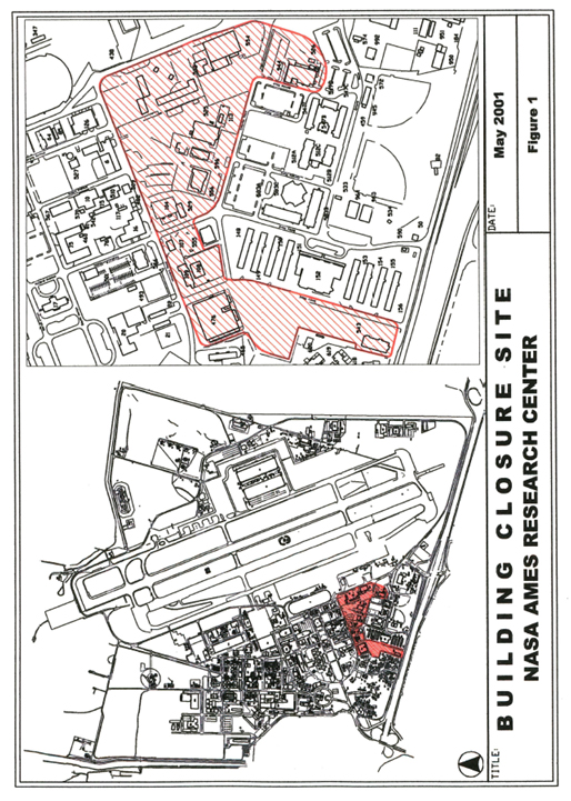
[Exhibit D - 6 of 11 - Closure Plan Number 5 Part 1 – Extracted Images – Figure 2]
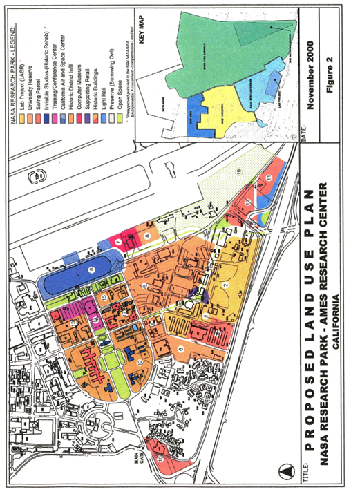
[Exhibit D - 6 of 11 - Closure Plan Number 5 Part 1 – Extracted Images – Figure 3]
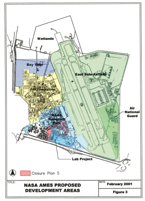
[Exhibit D - 6 of 11 - Closure Plan Number 5 Part 1 - Extracted Images – SITE 18]
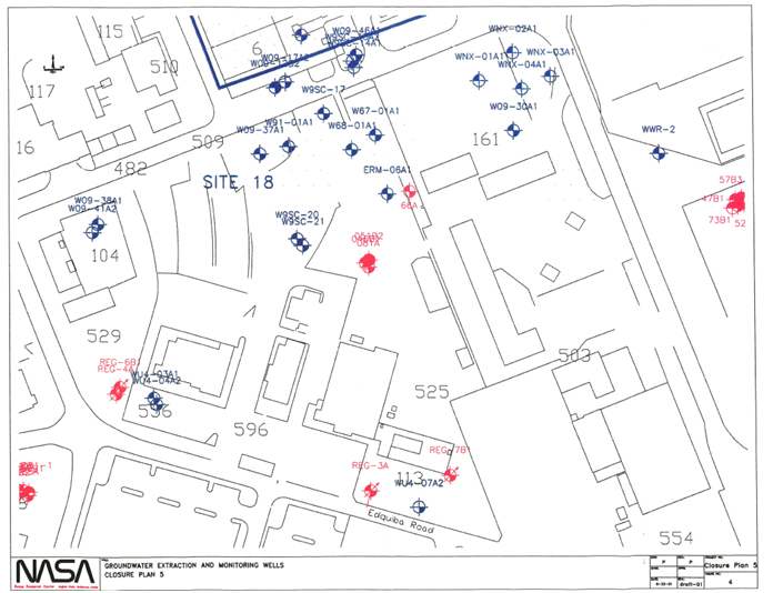
[Exhibit D - 6 of 11 - Closure Plan Number 5 Part 1 - Extracted Images – FIGURE 5]
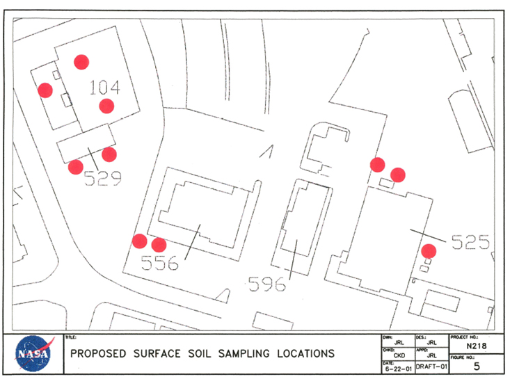
[Exhibit D - 6 of 11 - Closure Plan Number 5 Part 1 - Extracted Images – FIGURE 6]
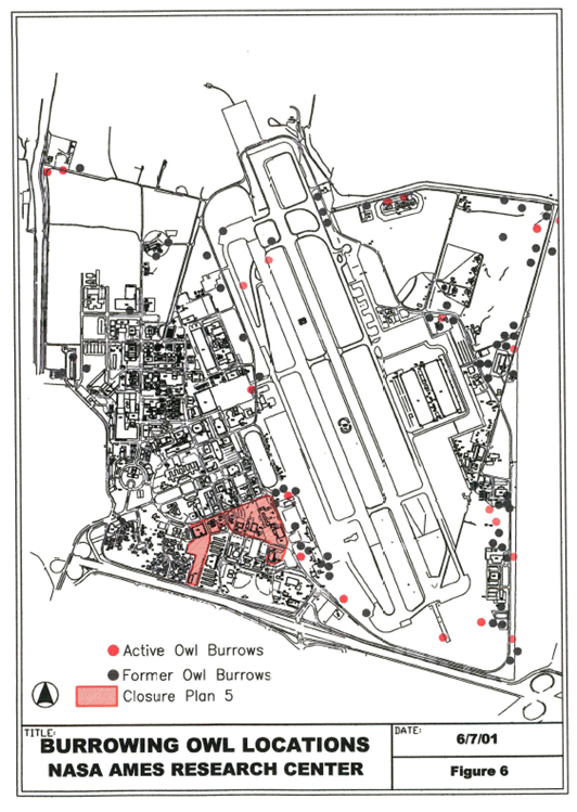
[Exhibit D - 6 of 11 - Closure Plan Number 5 Part 1 - Extracted Images – FIGURE 7]
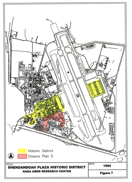
[Exhibit D - 6 of 11 - Closure Plan Number 5 Part 1 - Extracted Images – FIGURE 8]
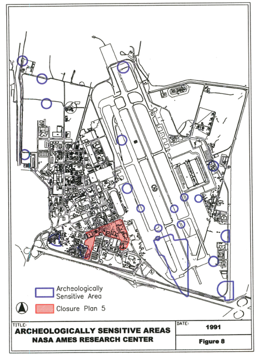
APPENDIX A
FACT SHEET
NASA AMES DEVELOPMENT PLAN
[Exhibit D - 6 of 11 - Closure Plan Number 5 Part 1 - Extracted Images – FACT SHEET]
[Exhibit D - 6 of 11 - Closure Plan Number 5 Part 1 - Extracted Images — FACT SHEET]
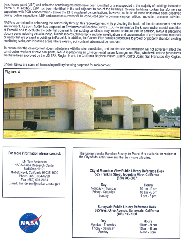
APPENDIX B
SANTA CLARA COUNTY STORAGE PERMITS AND INSPECTION REPORTS
NAVY ERA
[Exhibit D - 6 of 11 - Closure Plan Number 5 Part 1 - Extracted Images – Santa Clara County Health Department]
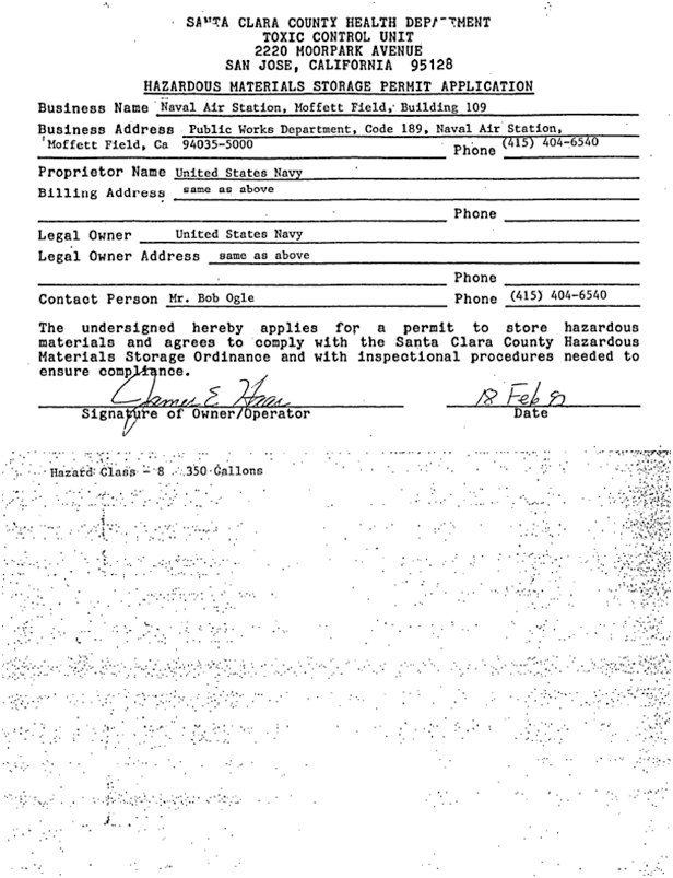
APPENDIX C
BIER REPORTS
[Exhibit D - 6 of 11 - Closure Plan Number 5 Part 1 - Extracted Images – MFDP ENVIROMENTAL OFFICE – Facility 104]
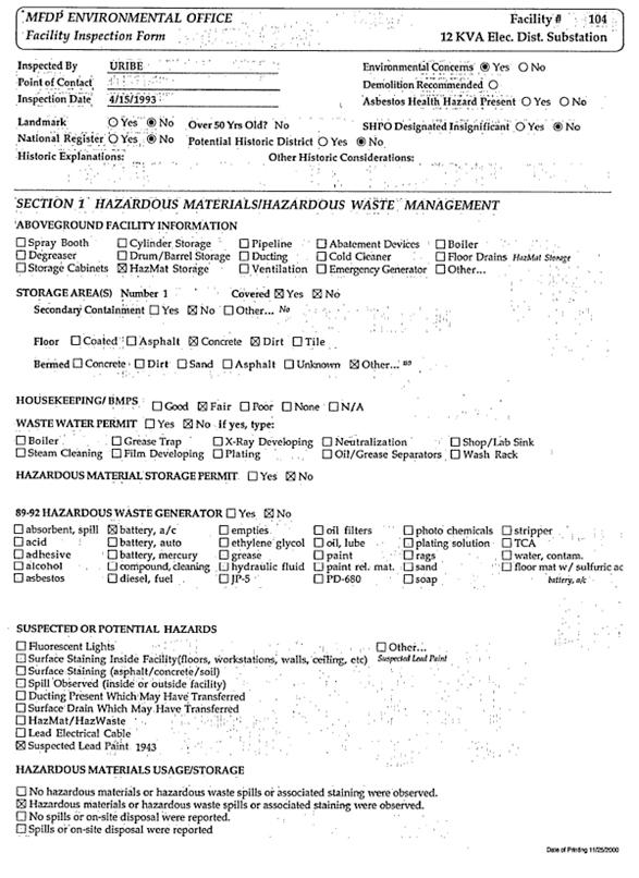
[Exhibit D - 6 of 11 - Closure Plan Number 5 Part 1 - Extracted Images – MFDP ENVIROMENTAL OFFICE – Facility 104]
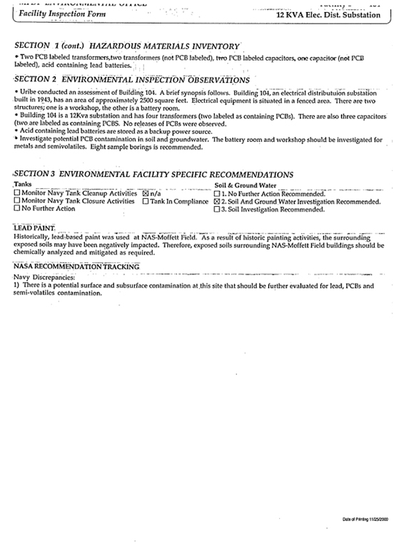
[Exhibit D - 6 of 11 - Closure Plan Number 5 Part 1 - Extracted Images – MFDP ENVIROMENTAL OFFICE – Facility 107]
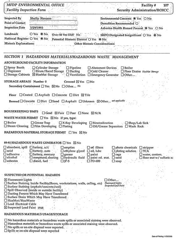
[Exhibit D - 6 of 11 - Closure Plan Number 5 Part 1 - Extracted Images – MFDP ENVIROMENTAL OFFICE – Facility 107]
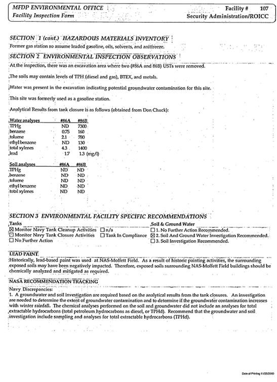
[Exhibit D - 6 of 11 - Closure Plan Number 5 Part 1 - Extracted Images – MFDP ENVIROMENTAL OFFICE – Facility 108]
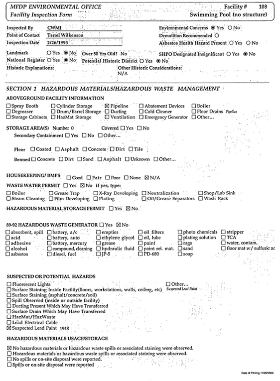
[Exhibit D - 6 of 11 - Closure Plan Number 5 Part 1 - Extracted Images – MFDP ENVIROMENTAL OFFICE – Facility 108]
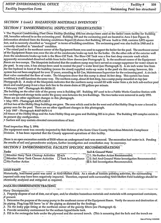
[Exhibit D - 6 of 11 - Closure Plan Number 5 Part 1 - Extracted Images – MFDP ENVIROMENTAL OFFICE – Facility 108]

[Exhibit D - 6 of 11 - Closure Plan Number 5 Part 1 - Extracted Images – MFDP ENVIROMENTAL OFFICE – Facility 109]

[Exhibit D - 6 of 11 - Closure Plan Number 5 Part 1 - Extracted Images – MFDP ENVIROMENTAL OFFICE – Facility 109]
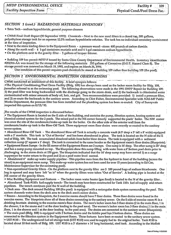
[Exhibit D - 6 of 11 - Closure Plan Number 5 Part 1 - Extracted Images – MFDP ENVIROMENTAL OFFICE – Facility 109 – Facility 109]
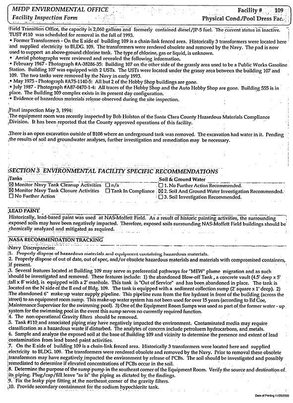
[Exhibit D - 6 of 11 - Closure Plan Number 5 Part 1 - Extracted Images – MFDP ENVIROMENTAL OFFICE – Facility 109 – Facility 109]

[Exhibit D - 6 of 11 - Closure Plan Number 5 Part 1 - Extracted Images – MFDP ENVIROMENTAL OFFICE – Facility 113]
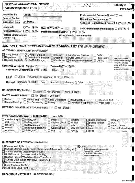
[Exhibit D - 6 of 11 - Closure Plan Number 5 Part 1 - Extracted Images – MFDP ENVIROMENTAL OFFICE – Facility 113]
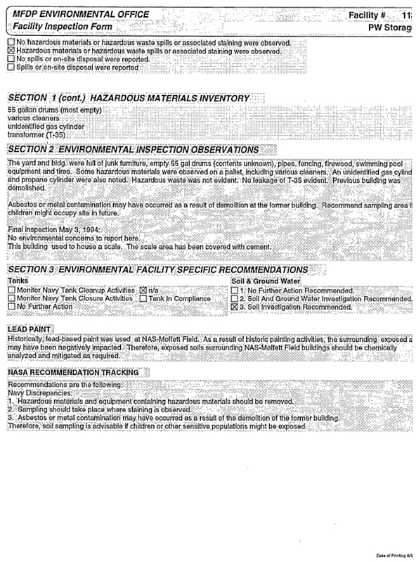
[Exhibit D - 6 of 11 - Closure Plan Number 5 Part 1 - Extracted Images – MFDP ENVIROMENTAL OFFICE – Facility 476]
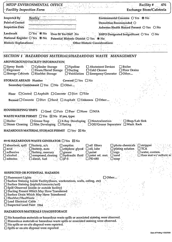
[Exhibit D - 6 of 11 - Closure Plan Number 5 Part 1 - Extracted Images – MFDP ENVIROMENTAL OFFICE – Facility 476]
[Exhibit D - 6 of 11 - Closure Plan Number 5 Part 1 - Extracted Images – MFDP ENVIROMENTAL OFFICE – Facility 503]
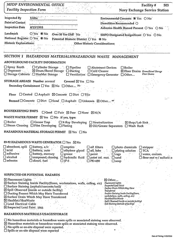
[Exhibit D - 6 of 11 - Closure Plan Number 5 Part 1 - Extracted Images – MFDP ENVIROMENTAL OFFICE – Facility 503]
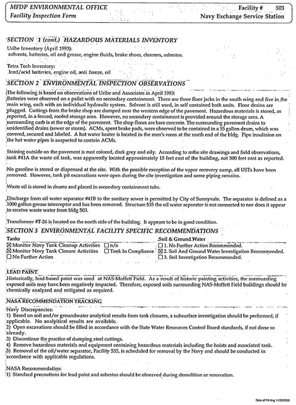
[Exhibit D - 6 of 11 - Closure Plan Number 5 Part 1 - Extracted Images – MFDP ENVIROMENTAL OFFICE – Facility 525]
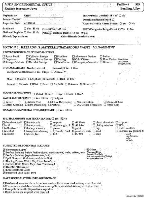
[Exhibit D - 6 of 11 - Closure Plan Number 5 Part 1 - Extracted Images – MFDP ENVIROMENTAL OFFICE – Facility 525]
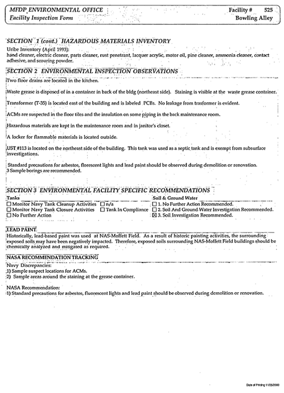
APPENDIX D
HISTORIC PHOTOGRAPHS
NAVY ERA
1
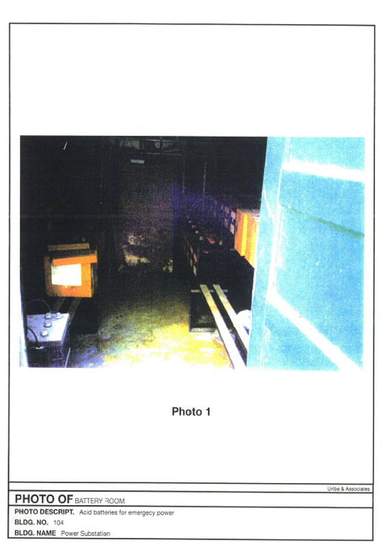
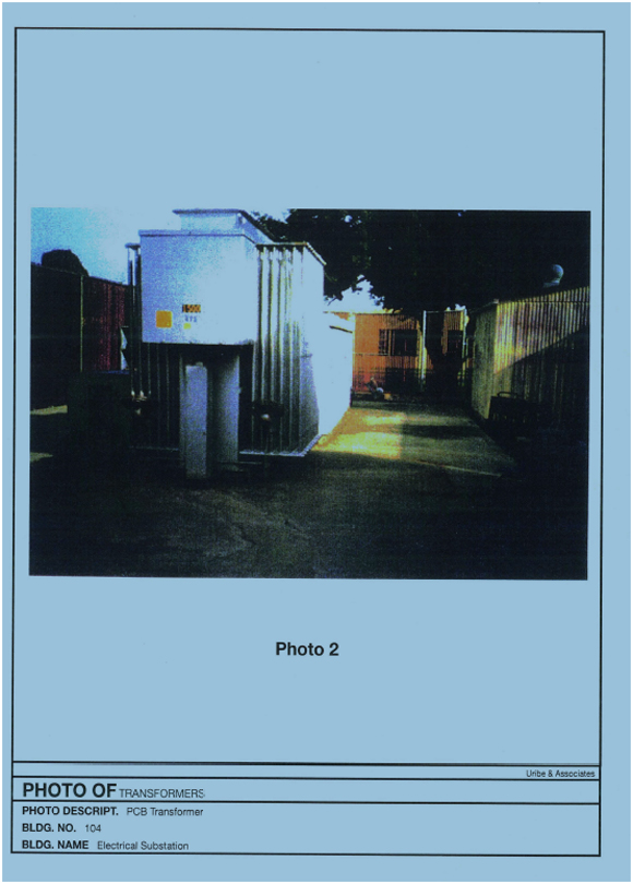
3
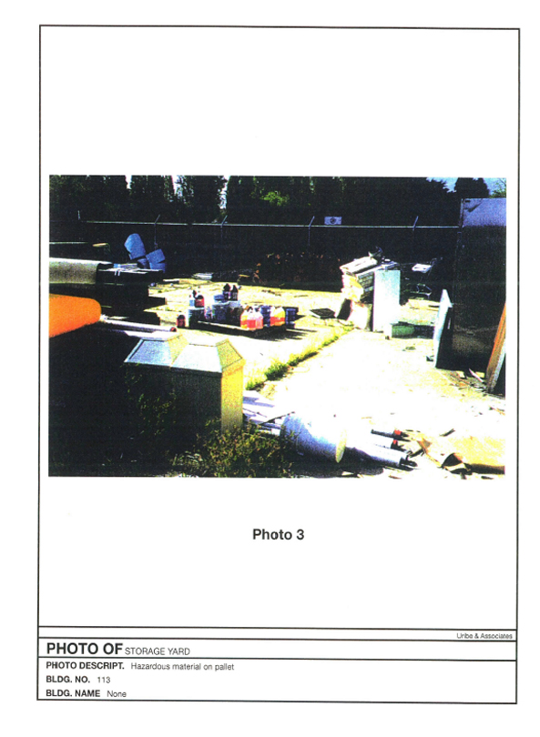
4
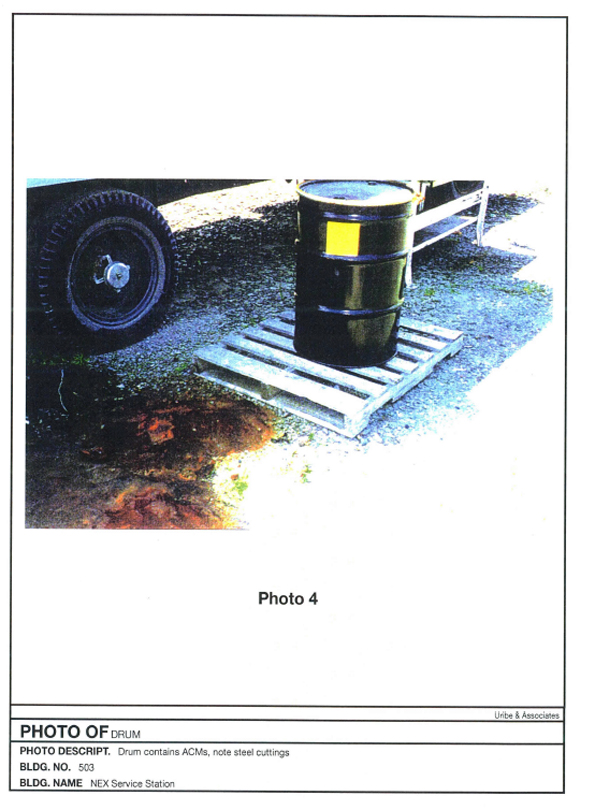
5
APPENDIX E
CURRENT PHOTOGRAPHS POST NAVY ERA
6
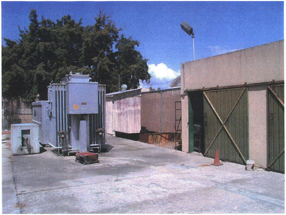
Photo 1: Building 104 Yard
7
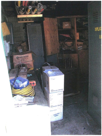
Photo 2: Building 104 Shed
8
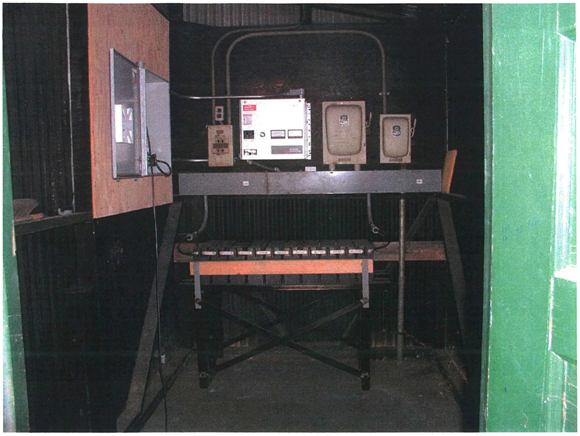
Photo 3: Building 104 Battery Room
9
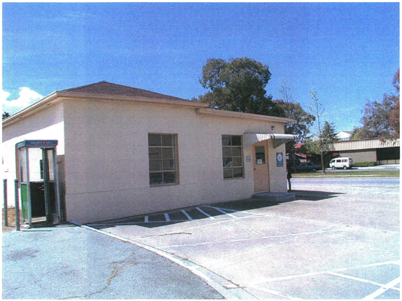
Photo 4: Building 107
10
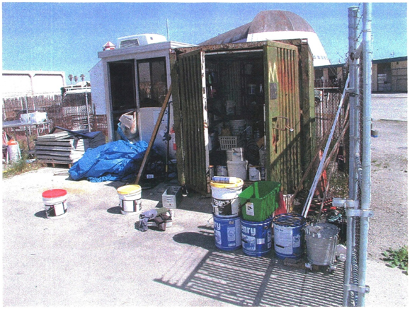
Photo 5: Building 113
11
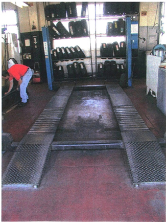
Photo 6: Building 503 Shop
12
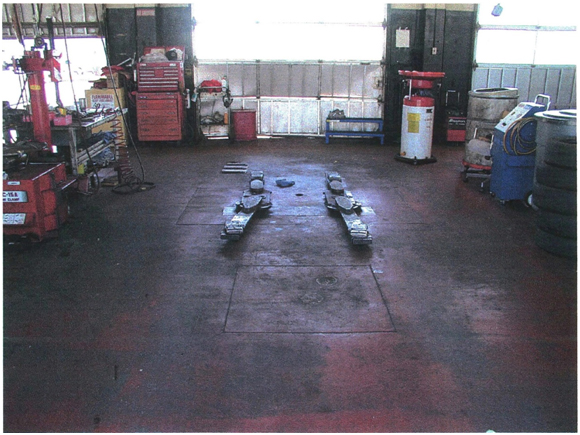
Photo 7: Building 503 Shop
13
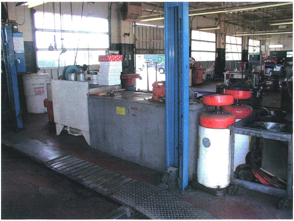
Photo 8: Building Shop
14
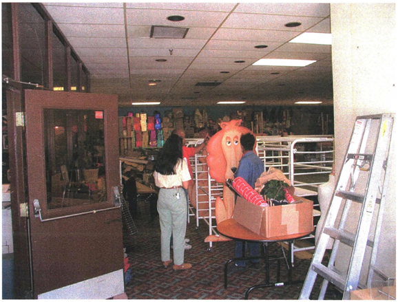
Photo 9: Building 525
15
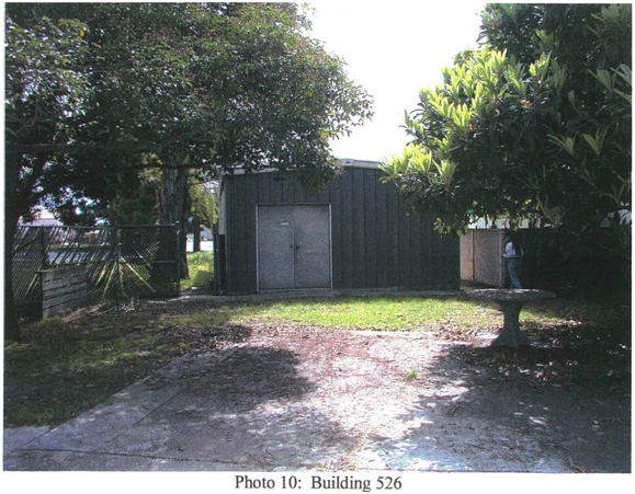
16
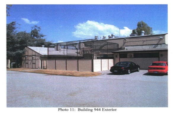
17
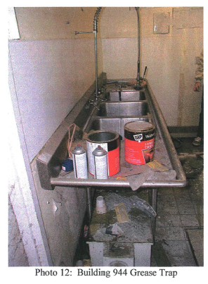
18
APPENDIX F
SANTA CLARA COUNTY PERMITS AND INSPECTIONS
POST NAVY ERA
19
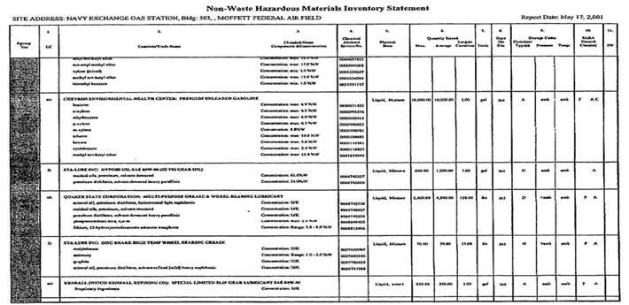
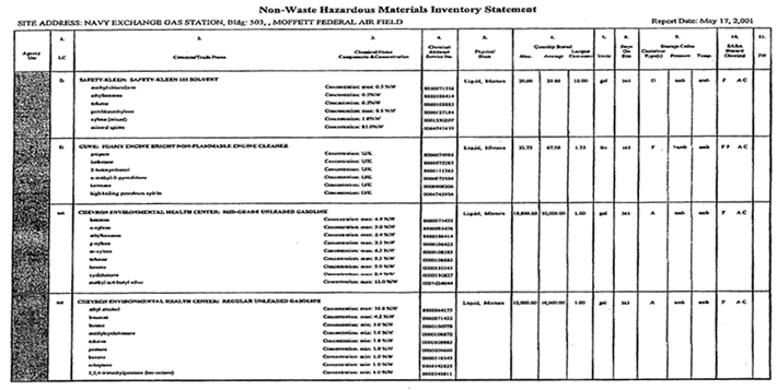
21
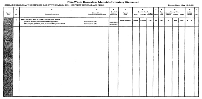
22
APPENDIX G
SANTA CLARA COUNTY FACILITY CLOSURE GUIDELINES
23

CLOSURE GUIDELINES FOR ABOVEGROUND
HAZARDOUS MATERIALS STORAGE FACILITIES
For Use by Unidocs Member Agencies or where approved by your Local Jurisdiction
| A. | General Information |
A facility closure plan demonstrates that hazardous materials at a closed facility have been transported, disposed of, or reused in a manner which eliminates the need for further maintenance and any threat to public health and safety or the environment. This document summarizes the requirements for closure of facilities where hazardous materials have been used, stored, or handled. (Note: Remodels or partial facility closures may require submittal of elements of a Closure Plan.)
| 1. | A closure permit and payment of appropriate fees may be required for the closure of any storage system which has previously contained any hazardous material. Please contact your local agency regarding applicable closure fees. |
| 2. | A completed Closure Application for Aboveground Hazardous Materials Storage Facilities (Closure Application) must be submitted to the appropriate local agency at least 30 days prior to the start of closure activities. (Note: Closure permits expire six months after local agency approval of the Closure Application.) |
| 3. | A facility closure which includes underground storage tanks must also include an Underground Storage Tank System Closure Permit Application/Closure Plan. |
| 4. | A facility closure which includes aboveground storage tanks (any container equal to or greater than sixty gallons in capacity) may require additional submittals. Please contact your local agency for details. |
| 5. | Please note that local agency requirements (e.g. inspections which may be required, etc.) will be specified in the “Comments” section at the bottom of the approved Closure Application. If inspections are required please schedule them at least 48 hours in advance. |
| 6. | If a groundwater monitoring well is to be closed or destroyed you must obtain a permit from the Santa Clara Valley Water District [phone no. (408) 927-0710). |
| 7. | Additional permits (e.g. demolition permits, electrical permits, plumbing permits, etc.) may be required by the Building Department or other state or federal agencies. |
| B. | Submittals |
The following must be submitted to the local agency before final closure sign-off:
| • | A completed Closure Application: |
| • | A Closure Plan (if required), along with applicable fees; |
| • | A Post Closure Report (if required), along with applicable supporting documentation. |
25
| C. | Closure Plan Requirements |
When required by the local agency, a Closure Plan would include but not be limited to:
| • | A schedule indicating projected start and completion dates; |
| • | A description of the size and type of equipment being closed, and the proposed final disposition. (Note: Equipment includes concrete, piping, duct work, tanks, and all other aboveground hazardous materials storage systems/areas}, |
| • | A site plan showing the location of the equipment or area being closed. Include all piping and ducting to be removed; |
| • | A list of the types of chemicals previously used or stored in the area to be closed (e.g. the facility’s Hazardous Materials Inventory Statements, etc.); |
| • | The procedures proposed to be used for decontamination of the facility and equipment (if required) and the proposed method of disposal for all hazardous wastes generated from cleaning operations. Decontamination procedures may include steam cleaning, rinsing, dismantling and removal of contaminated structural and non-structural portions of the building, etc. (Note: Contact the local Building Department regarding their requirements). |
| • | A brief description of how all hazardous materials will be removed or properly disposed of in a manner which complies with all state and federal laws. A new owner/operator may take responsibility for the hazardous materials as long as documentation is submitted which indicates acceptance of responsibility by the new owner/operator; |
| • | A description of the proposed sampling program (if required) including sample locations, constituents to be analyzed for, and test methods to be employed). Samples must be analyzed by laboratories certified by the State of California to perform the applicable test methods. (Note: Sampling maybe required by the local agency if contamination is suspected. An Inspector from the local agency must be present at the time of any sampling unless prior arrangements have been made with the local agency.) |
| D. | Post-Closure Report Requirements |
When required by the local agency, a Post-Closure Report would include but not be limited to:
| • | Documentation confirming compliance with all items in the approved Closure Plan; |
| • | Confirmation of disposition of all hazardous materials, including virgin and waste products, through |
| • | submittal of copies of bills of lading, bills of sale, TSDF-signed copies of hazardous waste manifests, etc.; |
| • | For any sampling performed, copies of: |
| 1. | Laboratory test results, including quality control/quality assurance data; |
| 2. | Completed sample chains-of-custody; |
| 3. | A site plan showing sample locations and, if applicable, depths; |
| 4. | A written description of sample collection and handling procedures; |
26
APPENDIX H
TABLE A-1
IDENTIFIED ILLICIT DISCHARGES, DISCHARGES REQUIRING
ADDITIONAL INVESTIGATION AND POTABLE WATER DISCHARGES
27
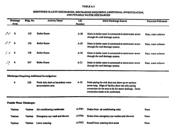
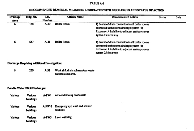
29
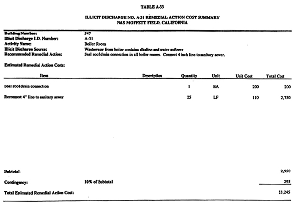
30
APPENDIX I
STORM WATER BEST MANAGEMENT PRACTICES
31
GOOD HOUSEKEEPING
BEST MANAGEMENT PRACTICES
DESCRIPTION
Good housekeeping practices are designed to maintain a clean and orderly work environment. Often the most effective first step towards preventing pollution in storm water from industrial sites simply involves using good common sense to improve the facility’s basic housekeeping methods. Poor housekeeping can result in more waste being generated than necessary and an increased potential for storm water contamination. A clean and orderly work area reduces the possibility of accidental spills caused by mishandling of chemicals and equipment, thereby dreducing safety hazards. Well maintained material and chemical storage areas should minimize discharges of materials / pollutants that could contaminate storm water. Simple procedures can be used to promote good housekeeping, including improved operation and maintenance of industrial machinery and processes, material storage practices, material inventory controls, routine and regular clean-up schedules, maintaining well organized work areas, and educational programs. It is the policy of NASA Ames Research Center that managers as well as line supervisors are responsible for ensuring that personnel are educated in proper environmental hazards management, including storm water pollution prevention.
TARGETED CONSTITUENTS
| • | Sediments |
| • | Nutrients |
| • | Floatable Materials |
| • | Oxygen Demanding Substances |
| • | Heavy Metals |
| • | Toxic Materials |
| • | Oil and Grease |
APPLICABILITY
This Best Management Practice is applicable to all industrial activities at Ames Research Complex.
32
REQUIREMENTS
| 1. | Conduct formal monthly inspections of all buildings and surrounding areas to ensure. |
| (a) | Outside areas are cleaned and organized; |
| (b) | Drips, leaks, or evidence of such, from equipment or pipes are contained; |
| (c) | Adequate space in work areas to minimize spill potential; |
| (d) | Garbage removed regularly; |
| (e) | Walkways and passageways easily accessible; |
| (f) | Walkways and passageways free of materials that could be spilled; |
| (g) | Evidence of dust from painting, sanding, or other industrial activities; and |
| (h) | Cleanup procedures for spilled materials exist. |
| 2. | An inspection log should be maintained in order to feed other environmental reporting requirements at Ames Research Complex. Moreover, a formal annual inspection of Ames Research Complex should be conducted to verify industrial activities in Storm Water Pollution Prevention Plan and identify new activities and Best Management Practices. |
| 3. | Conduct annual inventory of chemical substances, including hazardous materials and pollutants that are present on-site. This inventory shall meet the requirements of the OSHA-required inventory of chemicals and toxic substances. |
| 4. | Maintain a current file of all MSDS for chemicals and toxic substances. |
| 5. | Label chemical containers in accordance with OSHA, EPA, DOT and other applicable federal, state and local requirements. |
| 6. | Maintain dry and clean floors and ground surfaces by using brooms, shovels, vacuum cleaners, and cleaning machines. |
| 7. | Regularly pickup and dispose of garbage, debris and waste material. |
| 8. | Make sure equipment is working properly. |
| 9. | Routinely inspect for leaks or conditions that could lead to discharges of chemicals or contact of storm water with raw materials, intermediate materials, waste materials, or products. |
| 10. | Ensure that all employees understand spill cleanup procedures. |
| 11. | Improper storage can result in the release of materials and chemicals that can cause storm water runoff pollution. Proper storage techniques include: |
| (a) | Providing adequate aisle space to facilitate material transfer and easy access for inspections; |
| (b) | Storing containers, drums and bags away from direct traffic routes to prevent accidental containers from improper weight distribution; |
| (c) | Stacking containers according to manufacturer’s instructions to avoid damaging the containers from improper weight distribution; and |
| (d) | Storing containers on pallets or similar devices to prevent container corrosion, which can result from moisture on the ground. |
| 12. | Maintain an up-to-date inventory of all materials (hazardous and non-hazardous). This inventory helps to keep material costs down caused by overstocking, enables the tracking of materials stored and handled on site, and identifies which materials and activities pose the most risk to the environment. |
33
| 13. | Clearly mark on the inventory hazardous materials that require special handling, storage, use, and disposal considerations. |
| 14. | Keep the work site clean and orderly. Removing debris in a timely fashion. Sweep the area. |
| 15. | Cover materials of particular concern such as hazardous materials or sand piles that must remain outdoors, particularly during the rainy, season. |
| 16. | Educate employees who are doing the work. |
| 17. | Inform on-site contractors of NASA Ames Research Center policy. Include appropriate provisions in their contract to make certain proper housekeeping and disposal practices are implemented. |
| 18. | Make sure that nearby storm drains are well marked to minimize the chance of inadvertent disposal of residual paints and other liquids. |
| 19. | Do not dump waste liquids down the storm drain. |
| 20. | Advise concrete truck drivers to not wash their truck over the storm drain. |
| 21. | Cleaning equipment or tools over catch basins is prohibited. |
34
EROSION CONTROL AND SITE STABILIZATION
STORM WATER BEST MANAGEMENT PRACTICES
DESCRIPTION
This includes a description of all sediment and erosion control activities. This may include the planting and maintenance of vegetation, diversion of run-on and runoff, placement of sandbags, silt screens or other sediment control devices, etc. Any site where soils are exposed to water and wind can have soil erosion and sedimentation problems. Erosion is a natural process in which soil and rock materials is loosened and removed. Sedimentation occurs when soil particles are suspended in surface runoff or wind and are deposited in streams and other water bodies.
Human activities can accelerate erosion by removing vegetation, compacting or disturbing the soil, changing natural drainage patterns and by covering the ground with impermeable surfaces (pavement, concrete, and buildings). When the land surface is developed or “hardened” in this manner, storm water can not seep into or “infiltrate” the ground. The result is in larger amounts of water moving more quickly across the site, which can carry more sediment and other pollutants to creeks and streams. Because the vegetation primarily consists of marshlands and grasslands, soil erosion prevention is not required in many areas of Ames Research Complex. However, erosion prevention measures are considered during any construction and / or grounds maintenance activities.
TARGETED CONSTITUENTS
| • | Sediment |
| • | Heavy Metals |
| • | Toxic Materials |
APPLICABILITY
This Best Management Practice is applicable to all building, construction and landscaping activities at Ames Research Complex.
REQUIREMENTS
| 1. | Identify areas which, due topography, activities or other factors, have a high potential for significant soil erosion, and identify structural, vegetative, and / or stabilization measures used to limit erosion, |
| 2. | Retain as much vegetation (plants) onsite as possible. |
| 3. | Minimize the time that soil is exposed. Water exposed areas to control dust. |
| 4. | Prevent runoff from flowing across disturbed areas (divert the flow to vegetated areas). |
| 5. | Stabilize the disturbed soils as soon as possible by planting vegetation or hydroseeding. |
| 6. | Slow down the run-off flowing across site (regrading, silt fences, planting). |
| 7. | Provide drainage ways for the increased run-off (use grassy swales rather than concrete drains). |
| 8. | Remove sediment from storm water run-off before it leaves the site. |
| 9. | For large piles of soil where tarps or other covers are not feasible, place filtering media (e.g. straw bales, rocks, silt fences, etc.) around the base of each pile or at the storm drain inlet to remove these materials from rainwater run-off. |
35
CONSTRUCTION, DEMOLITION AND
EXCAVATION OPERATIONS
BEST MANAGEMENT PRACTICES
DESCRIPTION
Construction, demolition and excavation projects generate a great deal of dust, debris, waste materials and wastewaters that when improperly managed can result in prohibited discharges to the storm drainage system. Various construction projects occur at Ames Research Complex throughout the year. A Storm Water Pollution Prevention Plan is required in all contractor specifications. Furthermore, the California Storm Water Best Management Practice Handbook for Construction Activity is made available to construction contractors working at Ames Research Complex.
TARGETED CONSTITUENTS
| • | Sediment |
| • | Heavy Metals |
| • | Toxic Materials |
| • | Floatable Materials |
| • | Oil and Grease |
| • | Petroleum Products |
| • | Contaminated Groundwater |
APPLICABILITY
This Best Management Practice is applicable to all construction, demolition and excavation activities at Ames Research Complex that could potentially release pollutants to the storm water.
REQUIREMENTS
| 1) | Each job site should be managed in such a manner to avoid discharges of prohibited substances to the storm drain system. |
| 2) | Routine inspection of job site should be performed to ensure that construction, demolition and excavation materials (liquid or solid) are not entering the storm drain system. |
| 3) | Cleaning equipment or tools over catch basins is prohibited. |
| 4) | Keep the job site tidy and clean up debris regularly. |
| 5) | Storm drain catch basins should be covered to prevent pollutants and sediments from entering the storm drain system. |
36
| 6) | Special precautions should be employed if rain is forecast or if water is applied. These precautions should include, but are not limited to: |
| a) | Increased monitoring frequency for storm drains and to rectify ongoirig releases or to identify and prevent any possible release; and |
| b) | Reduction in activities that can cause material to come into contact with rain water |
| 7) | Following all construction, demolition and excavation activities; the job site should be swept to remove debris and residue. Catch basins should be vacuumed to remove sediment and debris. |
| 8) | Construction, demolition and excavation materials (gravel, sand, lumber, cement, chemicals, contaminated equipment, etc.) should be stored under a roof or structure or covered with a tarp or plastic visqueen. Covered items should be secured with ropes, sandbags, bricks, etc. to prevent or minimize contact with rainwater.. For large piles of soil or other construction materials where tarps or other covers are not feasible, place filtering media (e.g. straw bales, rocks, silt fences,etc.) around the base of each pile or at the storm drain inlet to remove these materials from rainwater run-off. Do not store items near catch basins. |
| 9) | Wet concrete and concrete cutting waters should be conducted to prevent discharge to the storm drains. Blocking off or plugging drains in the vicinity may be warranted. This can be done in a number of ways: placing weighted plastic visqueen over drain, using sandbags or spill control PIGS,etc.. |
| 10) | Equipment and machinery that contain residual concrete and concrete I asphalt cutting effluent should not be discharged to the storm drain. Estimate the amount of wastewater that will be generated and arrange to have a storage container (tank) available. Properly dispose of wastewater off-site. |
| 11) | Outdoor concrete work should be postponed if rain is forecast unless precautions are taken to prevent discharge of wet concrete and other construction debris to the storm drain. |
| 12) | During pain scraping operations, use impermeable ground cloths, such as plastic sheeting, to collect dust, paint chips, etc. |
| 13) | Use impermeable ground cloths while painting. Place in-use paint buckets in a pan or over plastic sheeting to ensure that accidental spills are not discharged to the storm drain. |
| 14) | Mixing of paint should take place indoors or in a place that is not exposed to the elements. |
| 15) | At the end of the workday, store paint buckets and other equipment away from contact with storm water in a secured, secondarily contained area. |
| 16) | Treat a paint spill as a chemical spill. Capture the material before it flows to the storm drain. Clean it up promptly. Report the event to NASA Environmental Services Office, Code QE, at 604-5602. |
37
| 17) | Outdoor Sandblasting should comply with the following: |
| a) | Tarpaulin or ground cloths should be placed beneath work area to capture the blasting medium and particles from the surface being cleaned; |
| b) | Consider curtailing sandblasting on a windy day, or if rain is forecast to minimize the amount of area that will require clean-up and to avoid sand waste from being washed into the storm drain; and |
| c) | Vacuum work area when job is complete. |
| 18) | If sandblasting lead paint, comply with the following: |
| a) | Obtain approval from the Environmental Services Office and the Occupational Safely, Health and Medical Services Office at 604-5602; |
| b) | Follow measures outline in “Outdoor Sandblasting” listed above; |
| c) | Air monitoring is required; and |
| d) | Follow OSHA regulations for worker safety. |
| 19) | For broken lines that contain anything other than potable water, the operator shall immediately notify the Environmental Office and initiate the following actions immediately: |
| a) | Berm the area to prevent run-off to storm drain; and |
| b) | Immediately block off adjacent storm drain catch basins. |
| 20) | Other applicable General Best Management Practices include: |
| a) | GOOD HOUSEKEEPING |
| b) | EROSION CONTROL |
| c) | MATERIAL HANDLING AND STORAGE and |
| d) | SOURCE REDUCTION |
38
BUILDING REPAIR, REMODELING AND CONSTRUCTION
STORM WATER BEST MANAGEMENT PRACTICES
DESCRIPTION
Building repair, remodeling and / or construction activity may vary from minor and normal building repair to major remodeling or the installation of a new facility on currently open space. These activities can generate pollutants that can reach storm water if proper care is not taken. The sources of these contaminants may be solvents, paints, paint and varnish removers, finishing residues, spent thinners, soap cleaners, kerosene, asphalt and concrete materials, adhesive residues and old asbestos installation.
TARGETED CONSTITUENTS
| • | Sediment |
| • | Heavy Metals |
| • | Toxic Materials |
| • | Floatable Materials |
| • | Oil and Grease |
APPLICABILITY
This Best Management Practice is applicable to all facilities at Ames Research Complex.
REQUIREMENTS
| 1) | Prevent or reduce the discharge of pollutants to storm water from building repair, remodeling and construction by using soil erosion controls, enclosing or covering building material storage areas, covering and / or diking storm drain catch basins, using good housekeeping practices, using safer alternative products and training employees. |
| 2) | Each job site should be managed in such a manner to avoid discharges of prohibited substances to the storm drain system. |
| 3) | Routine inspection of job site should be performed to ensure that construction, demolition and excavation materials (liquid or solid) are not entering the storm drain system. |
| 4) | Keep the job site tidy and clean up debris regularly. |
| 5) | Storm drain catch basins should be covered to prevent pollutants and sediments from entering the storm drain system. |
| 6) | Special precautions should be employed if rain is forecast or if water is applied. These precautions should include, but are not limited to: |
| a) | Increased monitoring frequency for storm drains and to rectify ongoing releases or to identify and prevent any possible release; and |
| b) | reduction in activities that can cause material to come into contact with rainwater. |
39
| 7) | Painting operations should follow: |
| a) | Application of lead based paint is prohibited; |
| b) | Painting operations should be properly enclosed or covered to avoid drift; |
| c) | Use temporary scaffolding to hang drop cloths or draperies to prevent drift. Use application equipment that minimizes overspray; |
| d) | If painting requires scraping or sand blasting of the existing surface, use a ground cloth to collect the chips. Dispose of the residue properly; |
| e) | If the paint contains lead or tributyl tin, it requires classification as a hazardous waste; |
| f) | mix paint indoors before using so that any spill will not be exposed to rain. Do so even during dry weather because cleanup of a spill will never be 100% effective. Dried paint will erode from a surface and be washed away by storms; and |
| g) | Properly store or dispose leftover paints. |
| 8) | Other applicable General Best Management Practices include: |
| a) | GOOD HOUSEKEEPING |
| b) | EROSION CONTROL |
| c) | MATERIAL HANDLING AND STORAGE and |
| d) | SOURCE REDUCTION |
40
APPENDIX J
DEPARTMENT OF PARKS AND RECREATION
(DPR) 5213 FORMS
41
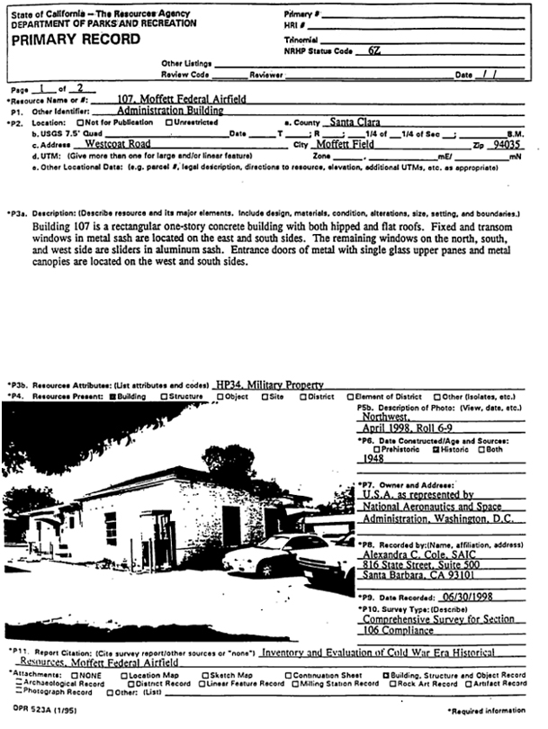
42
43
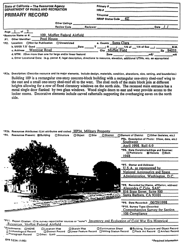
44
45
46
47
48
49
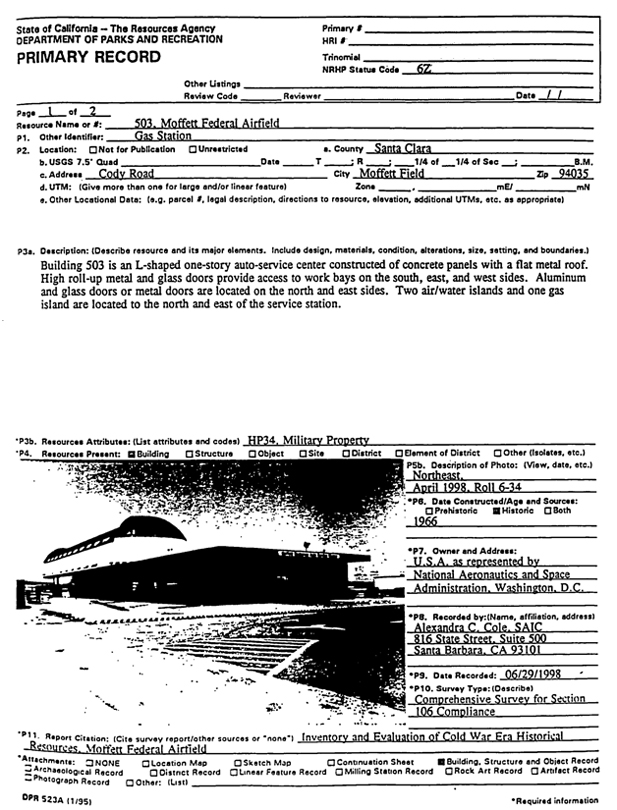
50
51
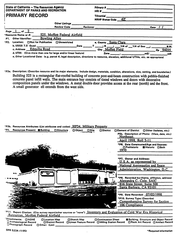
52
53
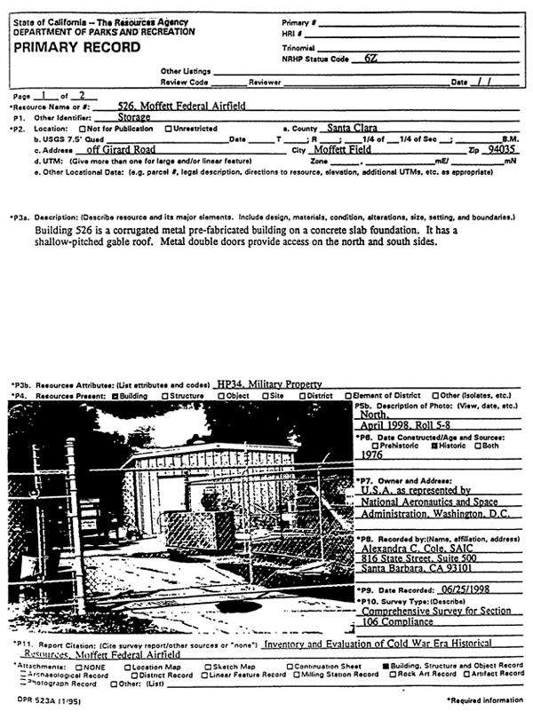
54
55
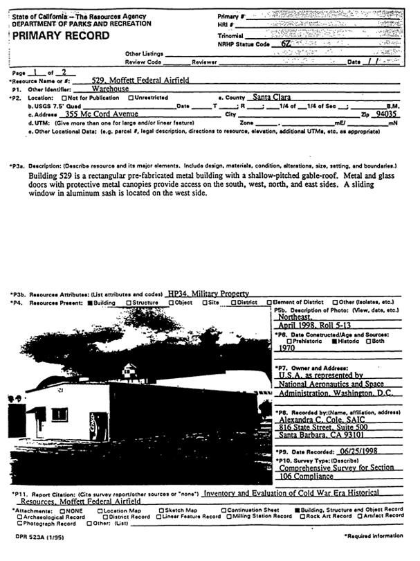
56
57
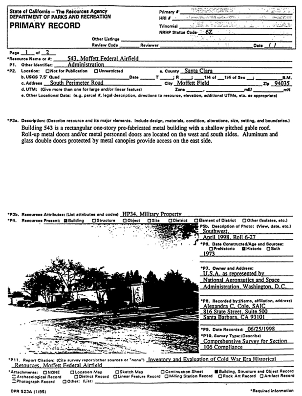
58
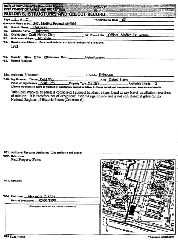
59
60
61
62
63
64
65
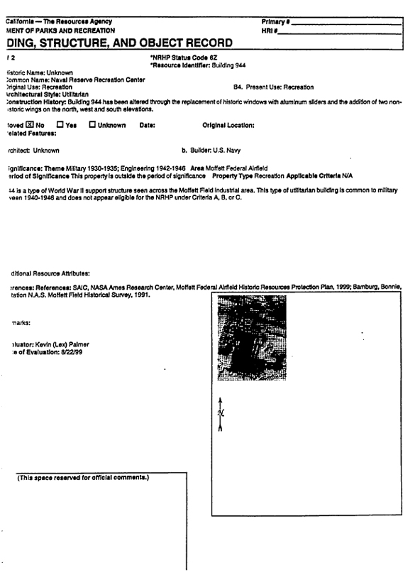
66
APPENDIX L
SANTA CLARA COUNTY UNDERGROUND/ABOVEGROUND
STORAGE INSTALLATION GUIDELINES
67
UNDERGROUND STORAGE TANK SYSTEM
INSTALLATION GUIDELINES
For Use by Unidocs Member Agencies or where approved by your Local Jurisdiction
Authority Cited: California Fire Code: Title 23, Div. 3, Ch. 16 CCR;
Hazardous Materials Storage Ordinance
A. General lnformation
These guidelines are applicable to installation of hazardous material underground storage tank systems (tanks and piping) regulated by all Unidocs Member Agencyjurisdictions. The guidelines serve as supplements to other requirements and/or guidelines (e.g. California Fire Code, Underground Storage Tank Regulations, Guidelines for Adoption of California Underground Storage Tank Regulations, manufacturers’ guidelines, etc.). Where such regulations and the guidelines conflict, the more stringent requirement shall apply.
| 1. | An installation permit and payment of appropriate fees shall be required for the installation or modification of any underground storage tank system which will be used for hazardous materials. |
| 2. | Contractors shall submit, or have on file with the local agency, information verifying that they possess a current State Contractor’s License (A, B, C36, C61/D40), Workmen’s Compensation Insurance, and (if required by the local jurisdiction) a business license. Contractor information may be obtained by calling the Contractors State License Board at (800) 321-2752. |
| 3. | Underground Service Alert should be contacted at (800) 642-2444 prior to the start of excavation. |
| 4. | The contractor shall be responsible for ensuring that conditions at the site provide for workplace safety, protection of the environment, and maintenance and integrity of nearby structures. |
| 5. | Under no circumstances shall any regulated material be placed into any underground tank system without approval of the local agency overseeing installation. |
| 6. | All tanks, piping, and equipment shall be installed and tested in accordance with the manufacturer’s recommendations/guidelines. |
B. Required Submittals
The following information shall be submitted to the local agency overseeing system installation:
| 1. | To be submitted with application: |
| ☐ | Completed Underground Storage Tank System lnstallation Supplement. |
| ☐ | Local agency permit application(s) (e.g. fire, building, plumbing, etc.) if required. |
| ☐ | sets of blueprints of the facility and underground storage tank system along with specifications on all materials to be used in construction. |
68
BENCHMARK
Asbestos, Lead and Mold Investigation
NASA-Ames (PAI Corporation)
Building 543
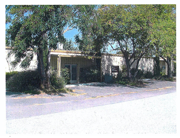
2
Table of Contents
| Section: | ||
| Executive Summary | ||
| 1 | Introduction | |
| 2 | Description of Building Construction and Systems | |
| 3 | Summary of Findings for Suspect Materials | |
| 4 | Material Information Tables | |
| 5 | Removal Cost Estimate Summary | |
| Appendices: | ||
| A | Definitions of Terms and Assessment Criteria | |
| B | Bulk Sampling Protocol and Analytical Methods | |
| C | Laboratory Bulk Sampling Reports | |
| D | Summary of Regulatory Requirements | |
| E | AHERA Building Inspector Certifications | |
| F | Drawings Indicating Material Locations | |
3
Executive Summary
Benchmark Environmental Engineering (Benchmark) was retained by NASA - Ames (PAI Corporation) to perform an Asbestos Hazard Emergency Response Act (AHERA) style asbestos survey of the Merchandise Exchange Offices (Building ID: Building 543), to determine the locations of accessible and to the extent feasible, inaccessible friable and non-friable asbestos containing building materials (ACBM).
This inspection was limited to the interior only. Pre-existing survey data was used to help provide a picture of existing condition of this building. Benchmark collected additional samples of the construction material to help supplement existing data, to contradict existing data or to provide additional data of materials not previously identified.
No friable asbestos-containing materials were observed in the building. Asbestos was detected in the following non-friable materials:
Floor Tile
Vinyl Tile
4
Section 1 Introduction
Benchmark Environmental Engineering (Benchmark) performed an Asbestos Hazard Emergency Response Act (AHERA) style asbestos survey of the Merchandise Exchange Offices located at Moffett Field, Mt. View, CA, to identify ACBM. This report identifies the locations and asbestos content of friable and non-friable ACBM, provides assessment of the friable ACBM in relation to the material’s hazard potential to building occupants and provides removal cost estimates.
This inspection was limited to the interior only. Pre-existing survey data was used to help provide a picture of existing condition of this building. Benchmark collected additional samples of the construction material to help supplement existing data, to contradict existing data or to provide additional data of materials not previously identified.
All identified suspect asbestos-containing materials are summarized in Section 3. Materials testing positive for asbestos including material assessments, recommended response actions, and quantities are described in Section 4. Removal cost estimates for asbestos-containing materials are included in Section 5.
Removal cost estimates (Section 5) are for budgeting purposes only and should not be used as a quote for removal of the materials. It is not our recommendation to remove these materials unless they are beyond repair, or planned demolition or renovation activities will disturb the materials. Estimates are based on recent pricing we have received from contractors performing similar work and may vary from actual prices obtained due to the actual scope of work, quantity of material removed, control measures specified and contractor work loads.
On Tuesday, August 14, 2001 Terri MacFarlane ( 90-2747), a California Certified Asbestos Consultant and Roy J. Mabus ( 92-0191), a California Certified Asbestos Consultant, from Benchmark, performed an asbestos survey of the building(s) in accordance with the Asbestos Hazard and Emergency Response Act of 1987 (AHERA).
DISCLAIMER
This report is prepared for the express use and benefit of NASA - Ames (PAI Corporation), its agents and employees. The information in this report or portions thereof may be required to be included in notifications to employees, contractors or other visitors to the building(s). This report is not intended to be used as a specification or work plan for any of the work suggested or recommended in this report.
This report is based upon conditions observed at the property and information made available to the surveyor. This report does not intend to identify all hazards or unsafe conditions, nor to indicate that other hazards or unsafe conditions do not exist at the premises.
5
Section 2 Description of Building Construction and Systems
| Number of Floors: 1 | Year Built: 1973 | Total Square Footage: 9,000 | ||
| Structural components consist of: | Concrete Slab | |||
| Exterior Wall construction components consist of: | Metal | |||
| Interior Wall construction components consist of: | Drywall | |||
| Interior ceiling components consist of: | Ceiling Tile | |||
| Roofing construction components consist of: | Metal | |||
| Heating and mechanical systems include: | Sprinkler Systems | |||
Building Description/Comments:
This facility is a one-story structure with a flat metal roof. The tan exterior is metal. It has a concrete slab foundation with metal exterior wall construction.
Comments:
There was a previous asbestos survey done by Tetra Tech, Inc. on July 9, 1993.
6
Section 3 Summary of Findings for Suspect Materials
The following table is a list of all materials at this building which were tested for the presence of asbestos or were assumed to contain asbestos along with overall sample results. Complete information on asbestos containing materials is included in Section 4 of this report.
Each unique material within the building is assigned a unique HM number by the surveyor at the time the survey is performed.
Section 3 and Section 4 are organized by building, surfacing, thermal systems insulation, flooring, walls, ceilings, roofing and miscellaneous materials.
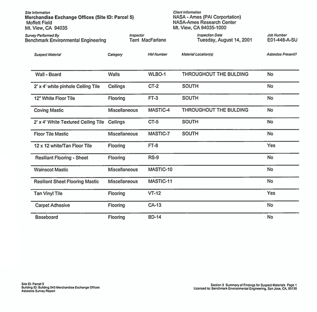
7
Section 3 Summary of Findings for Suspect Materials
The following table is a list of all materials at this building which were tested for the presence of asbestos or were assumed to contain asbestos along with overall sample results. Complete information on asbestos containing materials is included in Section 4 of this report.
Each unique material within the building is assigned a unique HM number by the surveyor at the time the survey is performed.
Section 3 and Section 4 are organized by building, surfacing, thermal systems insulation, flooring, walls, ceilings, roofing and miscellaneous materials.
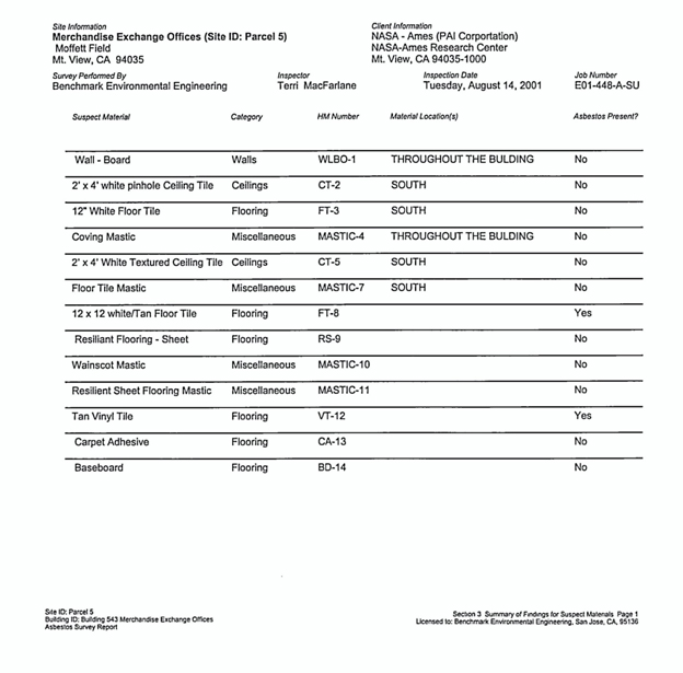
8
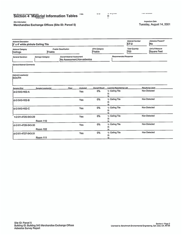
9
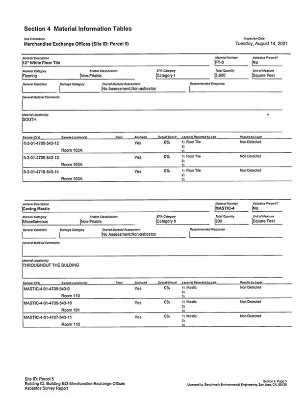
10
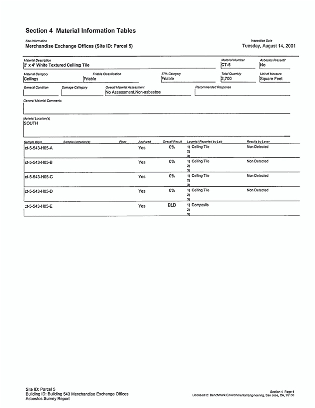
11
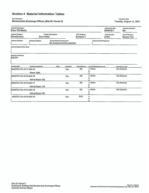
12
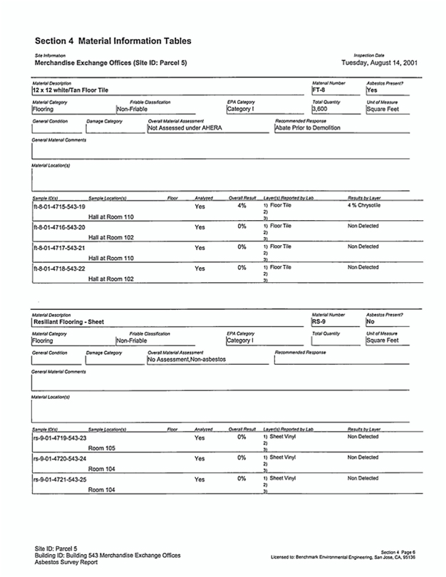
13
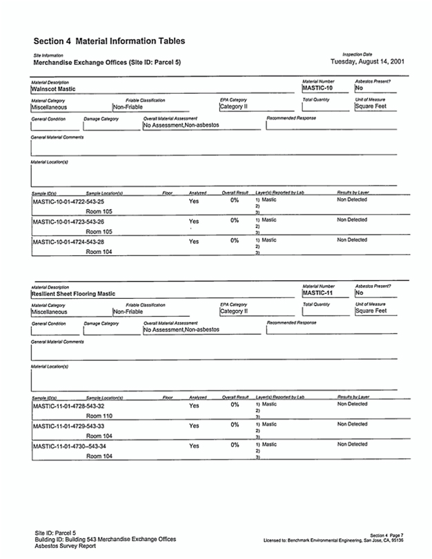
14
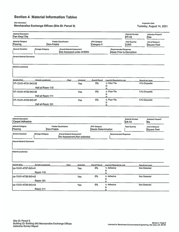
15
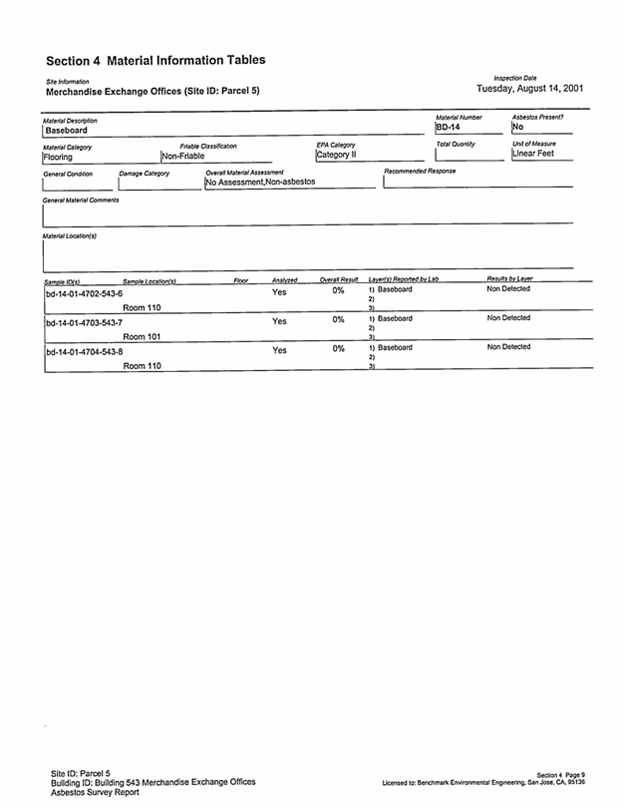
16
Section 5 Removal Cost Estimate Summary
These estimates are for budgeting purposes only and should not be used as a quote for removal of the materials. It is not our recommendation to remove these materials unless they are beyond repair, or planned demolition or renovation activities will disturb the materials. Estimates are based on recent pricing we have received from contractors performing similar work and may vary from actual prices obtained due to the actual scope of work, quantity of material removed, control measures specified and contractor work loads, etc.
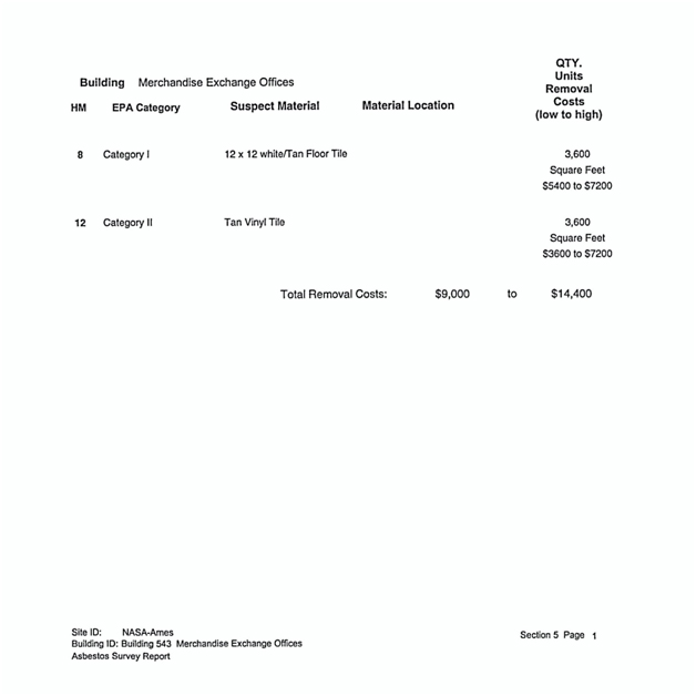
17
Appendix A
Definitions of Terms and Assessment Criteria
18
Definitions of Terms and Assessment Criteria
This survey report organizes information on each suspect ACBM identified in tables located in Section 4. This section describes how to interpret the data found on materials listed in Section 4.
Material description contains the description of the suspect homogeneous asbestos containing building material.
Material Serial Number is used to reference the material for reinspections, etc.
Asbestos type and content describes the type of asbestos and its percentage in the material.
Asbestos Results for positive materials are shown as a percentage. Samples having less than 1% asbestos are reported as containing “Trace” amounts of asbestos and samples with no detected asbestos are reported as “BLD” or below limit of detection.
Sample number(s) identifies a particular material sample obtained from a specific sample location. Sample numbers are used primarily for laboratory identification.
Sample Location identifies where the samples of this material were obtained.
Material Category categorizes each material as surfacing, TSI or miscellaneous.
Surfacing Materials - Asbestos containing materials that are sprayed-on, trawled-on or otherwise applied to surfaces, such as acoustical plaster on ceilings and fireproofing on structural members, or other materials on surfaces for acoustical, fireproofing, or other purposes.
Thermal Systems Insulation (TSI) - Asbestos containing materials applied to pipes, fittings, boilers, breaching, tanks, ducts or other interior structural components to prevent heat loss or gain or water condensation.
Miscellaneous Materials - Asbestos containing materials applied to or a part of building components that are not classified as surfacing materials or thermal systems insulation.
Quantity & Units reports approximate total quantity per unit of measure for each material.
Building(s) & Floor(s) specifies where a material is located.
Material Location describes where the material is found throughout the building.
Material Condition identifies the material as Friable, Non-friable or Jacketed (for thermal systems insulation only) if asbestos is present.
Friable - An asbestos containing material that can be crumbled, pulverized or reduced to powder, when dry, by hand pressure, such as spray applied fireproofing on structural steel members, spray applied acoustical ceiling materials or damaged thermal systems Insulation. Friable materials are of greatest concern due to their potential fiber release.
19
Non-Friable - An asbestos containing material where the asbestos is bound tightly in a matrix or sealed by a protective layer. Non-friable materials can become friable by being rendered to a crumbled, pulverized or powdered state, when dry, by crushing, sanding, sawing, shot-blasting, severe weathering or by other mechanically induced means. Common examples of non-friable materials are adhesives, floor tiles, transite and roofing materials.
Jacketed - An asbestos containing material applied to thermal systems insulation and “jacketed” with a protective outer layer such as canvas or metal to keep the material in good condition. Undamaged jacketed ACBM is considered non-friable. If the jacketing is damaged, the material is considered friable.
Damage Category describes the type of damage, if any, to the material. The following damage categories are used: None, Physical, Air, and Water.
Material Assessment identifies the condition of the material in relation to physical and water damage, delamination of the material from its substrate, the extent of the damage and the potential for damage from building conditions, such as, accessibility by building occupants, influence of vibration, etc. The six standard assessment categories ranked by hazard potential, with the first being the lowest hazard are as follows: 1) Potential for Damage, 2) Potential for Significant Damage, 3) Damaged, 4) Damaged with Potential for Damage, 5) Damaged with Potential for Significant Damage, and 6) Significantly Damaged. Only friable materials are assessed under AHERA regulations. Non-friable materials, unless damaged, are not assessed and can be assumed to be in good condition.
Damaged - The damage or deterioration of the material results in inadequate cohesion or adhesion with crumbling, blistering, water stains, marring or otherwise abraded over less than one-tenth (1/10) of the surface if the damage is evenly distributed or one-fourth (1/4) if the damage is localized.
Significant Damage - The damage or deterioration of the material results in inadequate adhesion or cohesion and the damage is extensive and severe with one or more of the following characteristics: 1) Crumbling or blistering over at least one-tenth (1/10) of the surface if evenly distributed, one-fourth (1/4) if the damage is localized; 2) Areas of the material hanging from the surface, delaminated, or showing adhesive failure; 3) Water stains, gouges or marred.
Recommended Response suggests the appropriate options for controlling or maintaining ACBM in a safe manner. There are four options used:
Operations & Maintenance (O&M) - A program designed to “manage” asbestos in-place. As long as asbestos containing materials remain in a building, an O&M program should be instituted to alert maintenance personnel, custodial workers and outside vendors of the existence and location of these materials and to set a policy for the maintenance of these materials. The material is usually only required to be removed if it is significantly damaged, prior to demolition of the building or if it will be disturbed by renovation activities.
20
Repair - The restoration of damaged or deteriorated asbestos containing building materials to an intact condition. Once the intact condition is established, the material should be included in an O&M program. The material is usually only required to be removed if it is significantly damaged, prior to demolition of the building or if it will be disturbed by renovation activities.
Abate Due to Condition - This material is significantly damaged and is unsafe in its current condition. The access to the area should be restricted to personnel equipped with appropriate personal protection. This material should be properly removed by a licensed contractor using workers trained in the safe removal of asbestos.
Abate Prior to Renovation - This material should be properly removed prior to planned renovation activities by a licensed contractor using workers trained in the safe removal of asbestos. This recommendation is usually made only on survey reports prepared prior to planned renovation activities.
Comments & Damage Description contains any additional information and or specific details of material damage are noted here.
EPA Category provides the appropriate material category as outlined in the NESHAPS regulation. The four options are friable, Category 1, Category 2, and needs determination.
Friable - Materials containing greater than 1% asbestos are always considered Regulated Asbestos Containing Materials (RACM) that require removal prior to building renovation or demolition activities that impact the material.
Category 1 - Materials that are bituminous non-friable and contain more than 1% asbestos that become RACM and require removal only when will be subject to grinding, cutting, sanding or abrading.
21
Appendix B
Bulk Sampling Protocol and Analytical Methods
22
Bulk Sampling Protocol and Analytical Methods
Bulk samples of suspect asbestos containing building materials were obtained using standard industrial hygiene techniques including wetting the material to minimize fiber release. Our personnel wore half-face air purifying respirators equipped with high efficiency particulate (HEPA) filters while obtaining samples
Our sampling strategy for suspect friable surfacing materials was based on the guidelines outlined in the EPA publication Asbestos in Buildings: Simplified Sampling Scheme for Friable Surfacing Materials, and the procedures outlined in 40 CFR 763, Subpart E (AHERA). For non-friable suspect materials, AHERA requires the building inspector to determine the appropriate number of samples to obtain and analyze. Usually one to three samples of non-friable materials are collected.
For each homogeneous material identified by visual inspection as suspect material, random samples are obtained. A single bulk sample is randomly selected from each homogeneous material for first-round testing. If the sample is positive, the remaining samples are not analyzed; if the sample is negative, the other samples are submitted for study. Every sample must be reported negative if the material is to be considered non-asbestos containing.
The bulk samples were delivered to an independent laboratory that participates in the bulk sample proficiency analysis program conducted by the United States Environmental Protection Agency and is accredited by the National Voluntary Laboratory Program (NVLAP). The samples were analyzed using Polarized Light Microscopy (PLM) with dispersion staining to estimate the percent of asbestos composition by volume. Samples with no observable asbestiform minerals are designated as None-Detected. Samples in which asbestiform minerals are observed, but exist in concentrations of less than one percent (<1%), are designated as present in Trace amounts; all other samples are designated as asbestos containing with the appropriate percent of asbestos noted.
23
Appendix C
Laboratory Bulk Sampling Reports
24
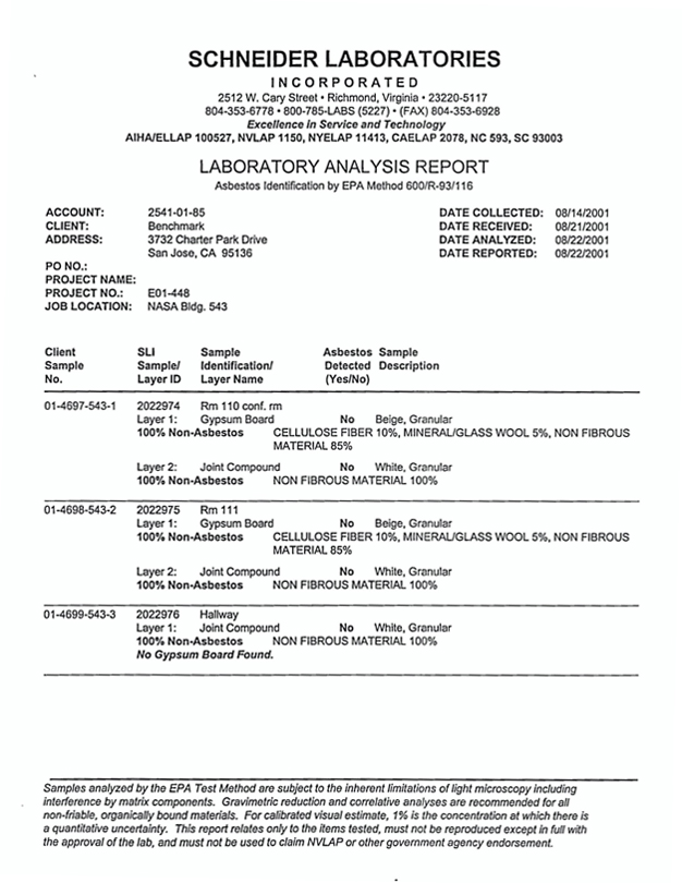
25
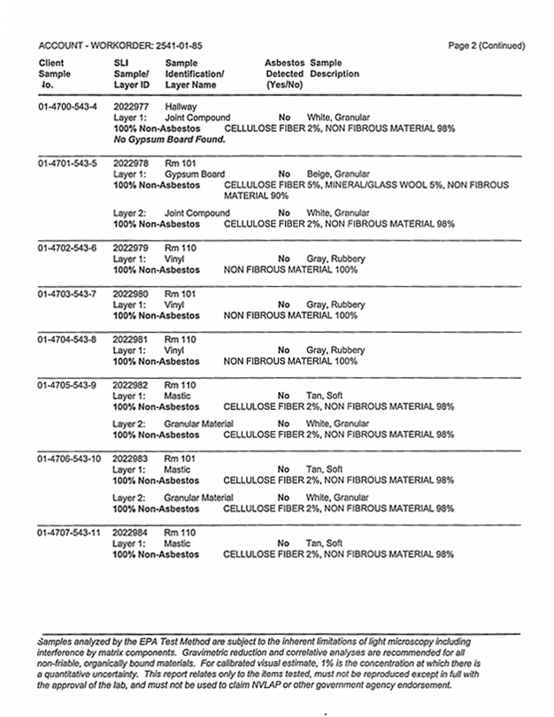
26
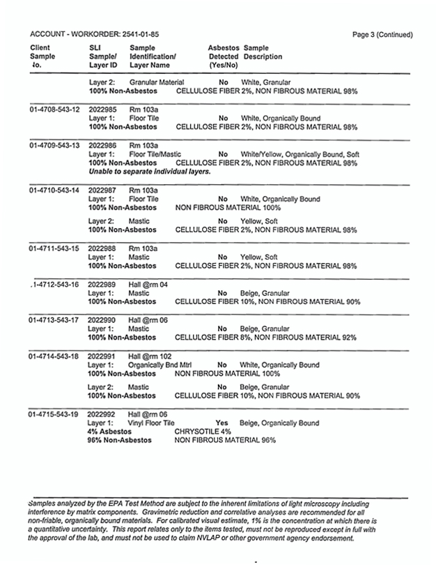
27
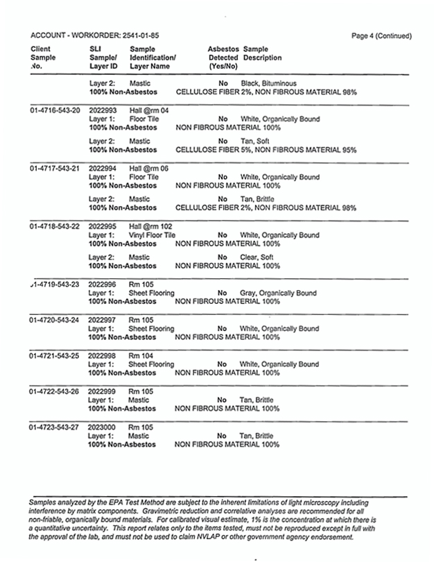
28
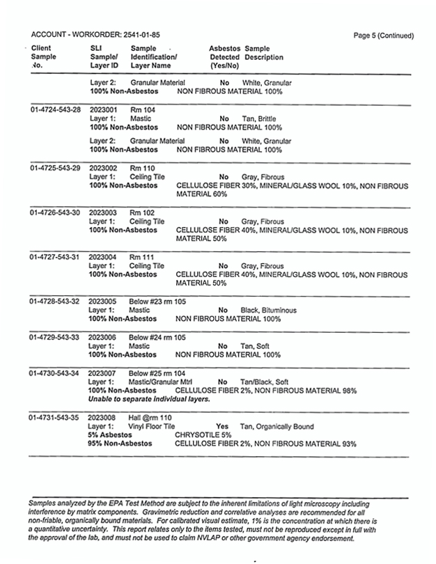
29
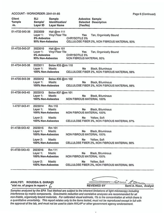
30
Appendix D
Summary of Regulatory Requirements
31
Appendix D Summary of Regulatory Requirements
This appendix provides a summary of building owner and manager requirements under various asbestos regulations promulgated by the Occupational Safety and Health Administration (OSHA) and the Environmental Protection Agency (EPA) to protect building occupants and employees from exposure to asbestos.
Survey Requirements
Prior to any renovation activity, OSHA and EPA regulations require that a complete asbestos survey be performed to determine if asbestos is present in any suspect asbestos containing material that will be present in the construction or work area. This survey report addresses accessible materials. It is recommended that prior to renovation activities, inaccessible areas that could contain asbestos materials be inspected.
Notification and Posting Requirements
Regulatory agencies feel that the building owner or manager should be responsible for knowing and communicating the locations of asbestos in their buildings to building employees, outside contractors and tenants to prevent exposure to asbestos.
Under the California Health and Safety Code, building owners and managers are required to provide annual notifications regarding known asbestos containing materials in their buildings to building employees, tenants, vendors and outside contractors. Therefore, specific information contained in this survey report is required to be included in the notification.
OSHA requires building employees, outside contractors, vendors and construction contractors bidding on or performing work in buildings be provided with notification regarding asbestos containing materials in their work areas. OSHA also requires that asbestos warning signs be posted in mechanical rooms.
Removal Requirements
Under EPA regulations, asbestos containing materials must be properly removed by licensed asbestos abatement contractors prior to renovation or demolition activities that would disturb friable materials or cause non-friable materials to become friable and a regulated material.
Repair of Damaged Materials and Cleanup of Debris
OSHA requires that asbestos containing debris be immediately cleaned up. It is recommended that damaged materials that may release fibers be repaired as soon as possible to prevent fiber release and potential exposures.
32
Training Requirements
OSHA requires employers whose employees are likely to or required to disturb asbestos to receive an asbestos training course. Refresher training is required to be provided annually.
33
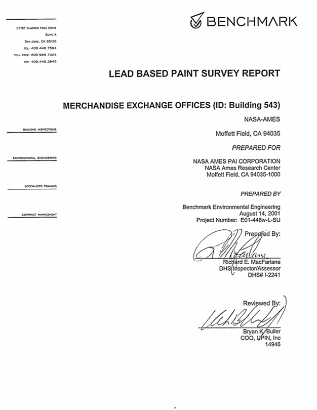
34
Table of Contents
| Section | ||
| Executive Summary | ||
| 1 |
Introduction | |
| 2 |
Scope of Services | |
| 3 |
Methodology | |
| 4 |
Findings and Observations | |
| APPENDICES | ||
| A |
XRF- Data Results Tables | |
| B |
Certification(s) | |
| C |
Site Map | |
| D |
Laboratory Results | |
35
EXECUTIVE SUMMARY
Benchmark Environmental Engineering was retained by PAI Corporation, to conduct a lead-based paint survey at Building 543, Merchandise Exchange Offices located at Moffett Field, California.
In order to determine if lead based paint was present, three (3) paint chip samples were collected and 80 assays were taken using an X-RAY FLUORESCENCE (XRF) instrument. The results indicated that the following building components were above the EPA and OHS level of 1.0 mg/ cm2 or 5000 PPM.
Lead-based Paint was identified on the following building component:
| Exterior: | Yellow Safety Paint. |
36
INTRODUCTION
Benchmark Environmental Engineering was retained by Mr. Kris McGlothlin, to conduct a lead-based paint survey at NASA Ames-PAI Corporation, Moffett Field, California.
Authorization to perform this survey was received via signed agreement to BENCHMARK from Mr. Kris McGlothlin, on or about May 1, 2001, as referenced by BENCHMARK’S proposal E01-448.
BACKGROUND
This facility is a one-story, 9,000 square foot structure. Built in 1973, it is concrete slab construction with metal exterior walls. The metal roof is flat and the tan exterior is metal.
WARRANTY
Benchmark Environmental Engineering warrants that the findings contained herein have been prepared with the level of care and skill exercised by experienced and knowledgeable environmental consultants who are appropriately licensed or otherwise trained to perform lead-related construction risk assessments and inspections pursuant to the scope of work required on this Project.
The survey included inspection of accessible materials. BENCHMARK did not inspect or sample inaccessible areas such as behind walls or within ductwork, and did not dismantle any part of the structure to survey inaccessible areas. For the purpose of this warranty, inaccessible is defined as areas of the building that could not be tested (sampled) without destruction of the structure or a portion of the structure. Inaccessible materials that are not visible to Benchmark’s inspectors are assumed to be lead containing.
Authorization to perform this survey was received by BENCHMARK from Mr. Kris McGlothlin, of The PAI Corporation, on May 1, 2001, as referenced by Benchmark’s Proposal E01-488.
The survey was conducted on August 14, 2001. A comprehensive site survey was performed based on the building plan. All building components identified in the specifications that may contain lead-based paint/coating were targeted for testing. (Exterior and interior walls, exterior and interior windows, doors and numerous associated components).
Sampling protocol for identification of lead-based paint was in accordance with The U.S. Department of Housing and Urban Development (HUD) Guidelines for the Evaluation and Control of Lead-Based Paint Hazards in Housing, Chapter 7. All suspect lead-coated surfaces were identified by building, wall, and building component, as such each component had a unique identification number.
The report establishes lead concentrations in painted surfaces as a general guidance tool for the purpose of conducting renovation activities for Building 543.
37
A total of 80 XRF assays and three (3) paint chip samples were collected within this building.
38
SCOPE OF SERVICES
Benchmark recognized the scope of work for the NASA Xxxx-XXX Corporation, to be composed of a Lead Based Paint Inspection for the Merchandise Exchange Offices (ID: Building 543). The survey consisted of testing for lead-base paint in general accordance with the U.S Department of Housing and Urban Development (HUD) guidelines for the evaluation and control of Lead-Based Paint Hazards in Housing, Chapter 7.
Certain building components that are adjacent to each other and not likely to have different painting histories have been grouped together into a single testing combination, as follows: Window Casings/Stops/Jambs/Aprons -Or- Door Jambs/Xxxxxx/Transoms/Casings and other door frame parts.
The following building components were inspected when applicable:
| • | Exterior Areas: |
| Walls | Windows | |
| Windowsills | Stair Handrails | |
| Doors | Door Molding | |
| Downspouts | Window Screen | |
| Building Trim | Skylight | |
| Balusters | Stair Handrail | |
| Stair Risers | Support Pillar |
| • | Interior Areas: |
| Walls | Windows | |
| Windowsills | Stair Treads | |
| Balusters | Doors | |
| Door Molding | Stair Xxxxxxxx | |
| Ceilings | Ceiling Molding | |
| Skylight | Floors | |
| Ceiling Molding | Grates | |
| Baseboards | Support Beams | |
| Electrical Box | Book Shelf | |
| Chair Rail | Wainscot |
Paint chip samples were collected from three (3) building components to provide conclusions that would be in compliance with DOSH 8 CCR 1532.1.
39
METHODOLOGY
GENERAL REFERENCES
Inspection, sampling, and assessment procedures were performed in general accordance with the guidelines published by The Department of Housing and Urban Development’s (HUD) 1995 Guidelines, Chapter 7. The survey consisted of three major activities: visual inspection, sampling, and analysis. Although these activities are listed separately, they are integrated tasks.
VISUAL INSPECTION
An inspector that is a Department of Health Services Certified Lead Inspector/ Risk Assessor performed the inspection. An initial building walkthrough was conducted to determine the presence of suspect materials that were accessible or exposed.
SAMPLING PROCEDURES
Following the walkthrough, the inspector selected samples areas of exposed or accessible materials identified as suspect LBP. EPA and HUD guidelines were used to determine the sampling protocol. Sampling locations were chosen to be representative of the homogeneous material.
X-RAY FLUORESCENCE (XRF) ANALYSIS
XRF instruments measure lead in paint by directing high energy X-rays and gamma rays into the paint, causing the lead atoms in the paint to emit X-rays which are detected by the instrument and converted to a measurement of the amount of lead in the paint. The EPA approved technology allows for measurement of X-rays without scraping or samples preparation to characterize substrate or matrix effects. The Spectrum Analyzer, Metals Analysis Probe (MAP 4) is combined with a microprocessor system that enables field-testing with a high degree of quality control and speed. Sample locations, descriptions, conditions, and measurement results are automatically recorded by the instrument and easily downloaded to a PC or laptop.
40
QUALITY CONTROL PROGRAM
Benchmark Environmental Engineering utilizes only DHS approved inspectors, which are certified to use radioactive instruments. The MAP 4 Spectrum Analyzer has on-board calibration routines, which continuously operate, and self-correct to minimize sampling error. This is known as substrate correcting software.
PAINT CHIP SAMPLE COLLECTION
A total of three (3) paint chip samples were collected in accordance with the HUD Evaluation and Control of Lead-Based Paint Hazards in Housing, Paint Chip Sampling. A two-inch by two-inch area was measured and delineated. The paint chip sample was collected with the use of a sharp stainless steel paint scraper. Paint was scraped directly off the substrate. The goal is remove all layers of paint equally, but none of the substrate. Paint chip samples collected in this fashion are reported in PPM or % by weight.
LEAD
Laboratory analysis was performed by Xxxxxxxxx Laboratories, Inc. Their AIHA Accredited Laboratory Identification Number is AIHA/ELLAP #100527, and CA ELAP #2078. Samples are analyzed by Flame Atomic Absorption in accordance with EPA’s “Standard Operating Procedures for Lead in Paint by Hotplate or Microwave based Acid digestions and Atomic Absorption or Inductively Coupled Plasma Emission Spectrometry” (1991), EPA/600/8-91/213, NTIS Document No. PB92-114172. Samples are prepared by hotplate digestion with nitric acid and hydrogen peroxide, and analyzed by Flame AA.
LABORATORY QUALITY CONTROL PROGRAM
Xxxxxxxxx Laboratories, Inc. maintains an in-house quality control program. This program involves blind reanalysis of ten percent of all samples, precision and accuracy controls, and use of standard bulk reference materials.
41
FINDINGS AND OBSERVATIONS
LEAD
A total of 80 assays were taken. The results indicated that 1 assay contained lead above the EPA and OHS level of 1.0 mg/ cm2 or greater. The components, which contain lead-based paint, are:
Exterior: Yellow Safety Paint.
Cal/OSHA’s Lead in Construction Standard, Title 8, CCR section 1532.1, is primarily concerned with worker protection when disturbing any detectable level of lead in paint or surface coatings.
Assays with results less than 1.0 mg/cm2 and paint chip samples with results less than 5000 ppm may create hazardous conditions if subjected to poor and/or prohibited work practices. Refer to Work Activities on the following page.
OSHA LEAD REGULATION SUMMARY
The Federal Occupational Safety and Health Administration (OSHA) has enacted an interim lead standard, which was adopted by Cal/OSHA as 8 CCR 1532.1. The purpose of both standards is to protect construction workers from exposure to lead. OSHA is primarily concerned with activities that disturb lead-containing material. Lead was used in most paints until the mid 1950’s and was banned in amounts in excess of 0.06% by weight in 1978 for most non-industrial paints by the Consumer Product Safety Commission (CPSC).
The new standard requires contractors and employers who perform activities that would disturb lead, must monitor their employees to determine whether they are being exposed in excess of the Action Level (AL) of 30 micrograms per cubic meter of air (ug/m3) over an eight-hour time weighted average (TWA) or the Permissible Exposure Limit (PEL) of 50 ug/m3 TWA. Monitoring is performed by personal exposure air sampling.
Even when concentrations are below the AL, an employer must provide employees with High Efficiency Particulate Air (HEPA) filtered vacuums, wetting agents and hand-washing facilities. If the exposure exceeds the AL or the PEL, other procedures such as containing the area, decontamination facilities and medical monitoring are required.
OSHA has identified several activities that pose varying levels of potential lead exposure to laborers disturbing lead-containing paint. Estimated exposure levels of lead are founded on the activity itself, rather than the concentrations of lead present in paint. Therefore, as an example, paints that contain 0.5% versus 15% of lead by weight or 0.8 mg/cm2 versus 3.5 mg/cm2 of lead in paint could present the same levels of potential exposure to workers depending on the activities that cause the disturbance and the administrative and engineering controls that are followed.
42
The following is a summary of work activities that disturb paint, the expected exposures and the respiratory protection requirements as outlined in the OSHA standards:
Class I Activities:
| Class I activities include: | Manual demolition, manual scraping, manual sanding, heat gun application, general cleanup, power tool cleaning with dust collection systems and spray painting activities. | |
| Potential Exposure: | 50 ug/m3 to 500 ug/m3 | |
| Minimum Respiratory Protection: Half mask air purifying respirator equipped with HEPA filters having a protection factor of 10. | ||
| Class II Activities: | ||
| Class II activities include: | Using lead-containing mortars, lead burning, lead riveting, rivet busting, power tool cleaning without dust collection systems, cleanup of dry expendable abrasives and abrasive blasting. | |
| Potential Exposure: | 500 ug/m3 to 2,500 ug/m3 | |
| Minimum Respiratory Protection: Full face powered air-purifying respirators equipped with HEPA filters having a protection Factor of 100. | ||
| Class III Activities: | ||
| Class II activities include: | Abrasive blasting, welding, cutting and torch burning on steel structures. | |
| Potential Exposure: | Greater than 2,500 ug/m3 | |
| Minimum Respiratory Protection: Full face supplied - air respirator operated in pressure demand mode or - the positive pressure mode. | ||
DOSH 8 CCR 1532.1 requires that an initial exposure assessment be performed if workers will be performing any of the trigger tasks found in 1532.1. It should be noted that the California Department of Health Services (OHS) has issued emergency work procedures for lead paint materials that in the absence of any other procedures are recommendations.
43
The following recommendations are general site specific work practice specifications.
| • | You must use “containment” when you sand, scrape, or disturb any detectable level of lead in paint or surface coatings. |
| • | Containment is required for abatement and/or any activity that or disturb any detectable level of lead in paint or surface coatings. |
| • | You must be OHS-certified (workers, supervisors, monitors, and inspectors) if you are conducting abatement. |
| • | You must follow an abatement plan. |
| • | A OHS -certified supervisor, monitor, and/or project designer must design an abatement project. |
| • | A clearance inspection by dust wipe sampling is required for abatement. |
RESULTS OF THE PAINT CHIP SAMPLES COLLECTED
Paint Chip Samples
NASA Xxxx-XXX Corporation
August 14, 2001
| Sample Number |
Component |
Location |
PPM |
% By Weight |
||||||||
| 01-4740-543-1 | Door | Interior | <70 | <0.007 | ||||||||
| 01-4741-543-2 | Ceiling | Ceiling | 40 | 0.004 | ||||||||
| 01-4742-543-3 | Wall 4 | Exterior Siding | <50 | <0.005 | ||||||||
LEAD WASTE DISPOSAL
The visual determination indicated that all building components that tested positive were in intact to poor condition (minor cracking to flaking and peeling). As such, these components need to be considered a lead hazard if flaking paint is not stabilized. All small debris (paint chips, rags, filters, and components smaller that 2”x2”) that may be generated during the paint stabilization process (paint preparation) should be considered Class I, lead hazardous waste. The debris generated from paint stabilization of LBP building components should be segregated from all other dust and debris. Building components, which tested positive, should be stabilized by a OHS-accredited Contractor.
Power washing may be conducted on the building. Run off water must be collected and analyzed by an accredited laboratory to meet the criteria established by the Clean Water Act, Resource Conservation and Recovery Act (RCRA 1972). Lead levels must not exceed 5mg/L.
44
CODES AND REGULATIONS LEAD-BASED PAINT
Federal and state regulations, which govern lead-based, paint work or hauling and disposal of lead-based paint waste materials include but are not limited to the following:
FEDERAL
Housing and Urban Development (HUD) 1995 Guidelines For The Evaluation and Control of
Lead-Based Paint in Housing
OSHA
Lead In Construction
29 CFR 1926.62
NESHAP
Emissions Standards
40 CFR 50.12
Lead-Based Paint Poisoning Prevention Act (LBPPPA), 1970.
Title 10 - Residential LBP Hazard Reduction Act, 1992, (amendment for LBPPPA, 1970)
Resource Conservation Recovery Act (RCRA)
STATE
Cal/OSHA
Lead In Construction
Title 8 CCR 1532.1
Department of Health Services (DHS)
Emergency Work Practice Regulations
Title 17 CCR, Division 1, Chp.
45
APPENDIX A
XRF - DATA RESULTS TABLE
46
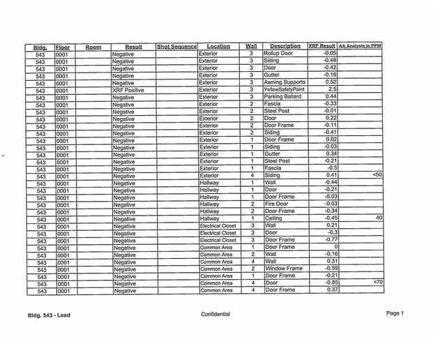
47
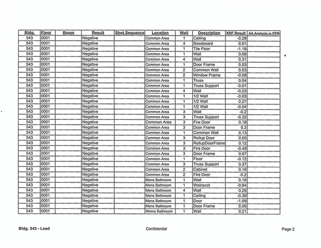
48
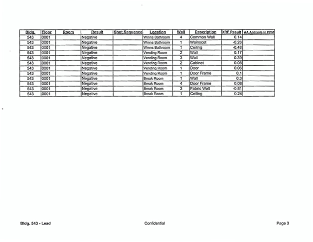
49
APPENDIX B
CERTIFICATION(S)
50
APPENDIX C
SITE MAP
51
APPENDIX D
LABORATORY RESULTS
52
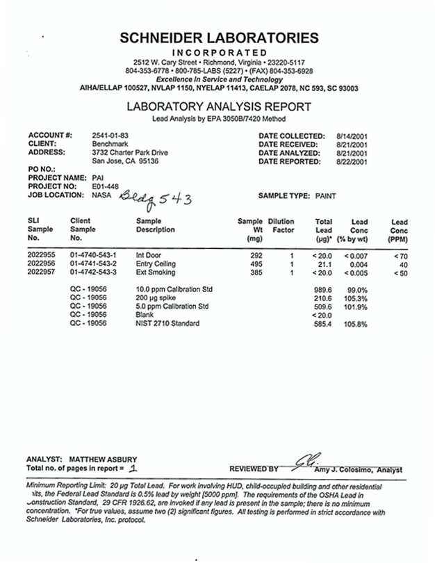
53
54
SCOPE OF SERVICES
Benchmark Environmental Engineering (Benchmark) was retained by PAI Corporation to provide a visual (only) evaluation on Building 543 of Xxxxxxx Field. Authorization to perform this consultation was received via written Agreement from PAI Corporation on August 1, 2001
Benchmark conducted a site visit on January 10, 2002.
Background:
There has not been a microbial investigation performed on this building.
Report:
The following report is defined in two sections:
Discoloration and Visible Mold.
55
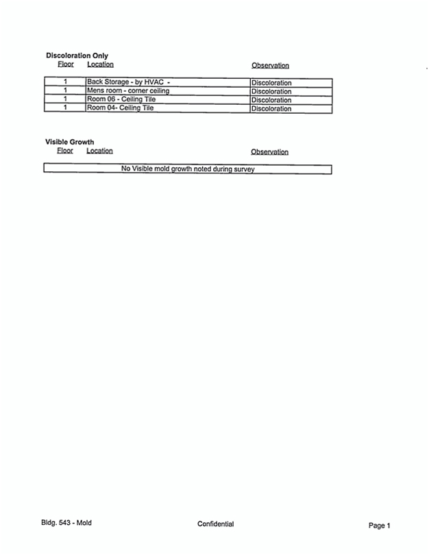
56

Table of Contents
| Section: | ||
| Executive Summary | ||
| 1 | Introduction | |
| 2 | Description of Building Construction and Systems | |
| 3 | Summary of Findings for Suspect Materials | |
| 4 | Material Information Tables | |
| 5 | Removal Cost Estimate Summary | |
| Appendices: | ||
| A | Definition of Terms and Assessment Criteria | |
| B | Bulk Sampling Protocol and analytical Methods | |
| C | Laboratory Bulk Sampling Reports | |
| D | Summary of Regulatory Requirements | |
| E | AHERA Building Inspector Certifications | |
| F | Drawings Indicating Material Locations | |
2
Executive Summary
Benchmark Environmental Engineering (Benchmark) was retained by NASA - Xxxx (PAI Corporation) to perform an Asbestos Hazard Emergency Response Act (AHERA) style asbestos survey of the Army Reserve Center 4 (Building ID: Building154), to determine the locations of accessible and to the extent feasible, inaccessible friable and non-friable asbestos containing building materials (ACBM).
This inspection included interior and exterior areas. Pre-existing survey data was used to help provide a picture of existing conditions of this building. Benchmark collected additional samples of the construction material to help supplement existing data, to contradict existing data or to provide additional data of materials not previously identified.
The entire interior of the building has been remodeled and all pre-existing materials have been removed and replaced with non-ACM material.
No friable asbestos-containing materials were observed in the building.
Asbestos was detected in the following non-friable materials:
Sink Undercoating
The following materials were assumed to contain asbestos:
Fire Door
| Site ID: 3-15 Yrs. | ||
| Building ID: Army Reserve Center 4 |
Executive Summary Page 1 | |
| Asbestos Survey Report |
Section 1 Introduction
Benchmark Environmental Engineering (Benchmark) performed an Asbestos Hazard Emergency Response Act (AHERA) style asbestos survey of the Army Reserve Center 4 located at Xxxxxxx Field, Mountain View, CA, to identify ACBM. This report identifies the locations and asbestos content of friable and non-friable ACBM, provides assessment of the friable ACBM in relation to the material’s hazard potential to building occupants and provides removal cost estimates.
This inspection included interior and exterior areas. Pre-existing survey data was used to help provide a picture of existing conditions of this building. Benchmark collected additional samples of the construction material to help supplement existing data, to contradict existing data or to provide additional data of materials not previously identified.
The entire interior of the building has been remodeled and all pre-existing materials have been removed and replaced with non-ACM material.
All identified suspect asbestos-containing materials are summarized in Section 3. Materials testing positive for asbestos including material assessments, recommended response actions, and quantities are described in Section 4. Removal cost estimates for asbestos-containing materials are included in Section 5.
Removal cost estimates (Section 5) are for budgeting purposes only and should not be used as a quote for removal of the materials. It is not our recommendation to remove these materials unless they are beyond repair, or planned demolition or renovation activities will disturb the materials. Estimates are based on recent pricing we have received from contractors performing similar work and may vary from actual prices obtained due to the actual scope of work, quantity of material removed, control measures specified and contractor work loads.
On Friday, November 2, 2001 Xxxxx XxxXxxxxxx ( 90-2747 ) , a California Certified Asbestos Consultant and Xxx X. Xxxxx
( 92-0191 ) , a California Certified Asbestos Consultant, from Benchmark, performed an asbestos survey of the building(s) in accordance with the Asbestos Hazard and Emergency Response Act of 1987 (AHERA).
DISCLAIMER
This report is prepared for the express use and benefit of NASA - Xxxx (PAI Corporation), its agents and employees. The information in this report or portions thereof may be required to be included in notifications to employees, contractors or other visitors to the building(s). This report is not intended to be used as a specification or work plan for any of the work suggested or recommended in this report.
| Site ID: 3-15 Yrs. | ||
| Building ID: Army Reserve Center 4 |
Section 1 Page 1 | |
| Asbestos Survey Report |
This report is based upon conditions observed at the property and information made available to the surveyor. This report does not intend to identify all hazards or unsafe conditions, nor to indicate that other hazards or unsafe conditions do not exist at the premises.
| Site ID: 3-15 Yrs. | ||
| Building ID: Army Reserve Center 4 |
Section 1 Page 2 | |
| Asbestos Survey Report |
Section 2 Description of Building Construction and Systems
| Number of Floors: 3 | Year Built: 1953 | Total Square Footage: 9,285 |
| Structural components consist of: | Concrete Foundation | |
| Exterior Wall construction components consist of: | Concrete | |
| Interior Wall construction components consist of: | Drywall | |
| Interior ceiling components consist of: | Ceiling Tile | |
Building Description/Comments:
This is a two-story structure with a basement. Built in 1953, the building construction is concrete over a concrete foundation and with a flat composite roof. The concrete exterior is tan.
Comments:
There was a previous asbestos survey done by Tetra Tech, Inc. on January 19, 1993.
| Site ID: 3-15 Yrs. | ||
| Building ID: Army Reserve Center 4 |
Section 2 Page 1 | |
| Asbestos Survey Report |
Section 3 Summary of Findings for Suspect Materials
The following table is a list of all materials at this building which were tested for the presence of asbestos or were assumed to contain asbestos along with overall sample results. Complete information on asbestos containing materials is included in Section 4 of this report.
Each unique material within the building is assigned a unique HM number by the surveyor at the time the survey is performed.
Section 3 and Section 4 are organized by building, surfacing, thermal systems insulation, flooring, walls, ceilings, roofing and miscellaneous materials.
| Site Information | Client Information | |
| Army Reserve Center 4 (Site ID: 3-15 Yrs.) | NASA - Xxxx (PAI Corporation) | |
| Xxxxxxx Field | NASA-Xxxx Research Center | |
| Mountain View, CA 94035 | Mt. View, CA 94035-1000 |
| Survey Performed By | Inspector | Inspection Date | Job Number | |||
| Benchmark Environmental Engineering | Xxxxx XxxXxxxxxx | Friday, November 2, 2001 | E01-612-A-SU |
| Suspect Material |
Category |
HM Number |
Material Location(s) |
Asbestos Present? | ||||
| Roofing Material | Roofing | RM-2 | No |
| Site ID: 3-15 Yrs. | ||
| Building ID: Army Reserve Center 4 |
Section 3 Page 1 | |
| Asbestos Survey Report |
Section 4 Material Information Tables
| Site Information | Client Information | |
| Army Reserve Center 4 (Site ID: 3-15 Yrs.) | NASA - Xxxx (PAI Corporation) | |
| Xxxxxxx Field | NASA-Xxxx Research Center | |
| Mountain View, CA 94035 | Mt. View, CA 94035-1000 |
| Survey Performed By | Inspector | Inspection Date | Job Number | |||
| Benchmark Environmental Engineering | Xxxxx XxxXxxxxxx | Friday, November 2, 2001 | E01-612-A-SU |
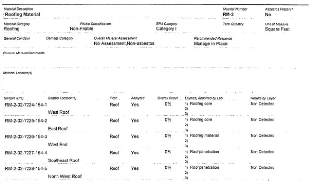
| Site ID: 3-15 Yrs. | ||
| Building ID: Army Reserve Center 4 |
Section 4 Page 1 | |
| Asbestos Survey Report |
Appendix A
Definitions of Terms and Assessment Criteria
Definitions of Terms and Assessment Criteria
This survey report organizes information on each suspect ACBM identified in tables located in Section 4. This section describes how to interpret the data found on materials listed in Section 4.
Material description contains the description of the suspect homogeneous asbestos containing building material.
Material Serial Number is used to reference the material for reinspections, etc.
Asbestos type and content describes the type of asbestos and its percentage in the material.
Asbestos Results for positive materials are shown as a percentage. Samples having less than 1% asbestos are reported as containing “Trace” amounts of asbestos and samples with no detected asbestos are reported as “BLD” or below limit of detection.
Sample number(s) identifies a particular material sample obtained from a specific sample location. Sample numbers are used primarily for laboratory identification.
Sample Location identifies where the samples of this material were obtained.
Material Category categorizes each material as surfacing, TSI or miscellaneous.
Surfacing Materials - Asbestos containing materials that are sprayed-on, trawled-on or otherwise applied to surfaces, such as acoustical plaster on ceilings and fireproofing on structural members, or other materials on surfaces for acoustical, fireproofing, or other purposes.
Thermal Systems Insulation (TSI) - Asbestos containing materials applied to pipes, fittings, boilers, breaching, tanks, ducts or other interior structural components to prevent heat loss or gain or water condensation.
Miscellaneous Materials - Asbestos containing materials applied to or a part of building components that are not classified as surfacing materials or thermal systems insulation.
Quantity & Units reports approximate total quantity per unit of measure for each material. Building(s) & Floor(s) specifies where a material is located.
Material Location describes where the material is found throughout the building.
Material Condition identifies the material as Friable, Non-friable or Jacketed (for thermal systems insulation only) if asbestos is present.
Friable - An asbestos containing material that can be crumbled, pulverized or reduced to powder, when dry, by hand pressure, such as spray applied fireproofing on structural steel members, spray applied acoustical ceiling materials or damaged thermal systems insulation. Friable materials are of greatest concern due to their potential fiber release.
Non-Friable - An asbestos containing material where the asbestos is bound tightly in a matrix or sealed by a protective layer. Non-friable materials can become friable by being rendered to a crumbled, pulverized or powdered state, when dry, by crushing, sanding, sawing, shot-blasting, severe weathering or by other mechanically induced means. Common examples of non-friable materials are adhesives, floor tiles, transite and roofing materials.
Jacketed - An asbestos containing material applied to thermal systems insulation and “jacketed” with a protective outer layer such as canvas or metal to keep the material in good condition. Undamaged jacketed ACBM is considered non-friable. If the jacketing is damaged, the material is considered friable.
Damage Category describes the type of damage, if any, to the material. The following damage categories are used: None, Physical, Air, and Water.
Material Assessment identifies the condition of the material in relation to physical and water damage, delamination of the material from its substrate, the extent of the damage and the potential for damage from building conditions, such as, accessibility by building occupants, influence of vibration, etc. The six standard assessment categories ranked by hazard potential, with the first being the lowest hazard are as follows: 1) Potential for Damage, 2) Potential for Significant Damage, 3) Damaged, 4) Damaged with Potential for Damage, 5) Damaged with Potential for Significant Damage, and 6) Significantly Damaged. Only friable materials are assessed under AHERA regulations. Non-friable materials, unless damaged, are not assessed and can be assumed to be in good condition.
Damaged - The damage or deterioration of the material results in inadequate cohesion or adhesion with crumbling, blistering, water stains, marring or otherwise abraded over less than on-tenth (1/10) of the surface if the damage is evenly distributed or one-fourth (1/4) if the damage is localized.
Significant Damage - The damage or deterioration of the material results in inadequate adhesion or cohesion and the damage is extensive and severe with one or more of the following characteristics: 1) Crumbling or blistering over at least one-tenth (1/1O) of the surface if evenly distributed, one-fourth (1/4) if the damage is localized; 2) Areas of the material hanging from the surface, delaminated, or showing adhesive failure; 3) Water stains, gouges or marred.
Recommended Response suggests the appropriate options for controlling or maintaining ACBM in a safe manner. There are four options used:
Operations & Maintenance (O&M) - A program designed to “manage” asbestos in-place. As long as asbestos containing materials remain in a building, an O&M program should be instituted to alert maintenance personnel, custodial workers and outside vendors of the existence and location of these materials and to set a policy for the maintenance of these materials. The material is usually only required to be removed if it is significantly damaged, prior to demolition of the building or if it will be disturbed by renovation activities.
Repair - The restoration of damaged or deteriorated asbestos containing building materials to an intact condition. Once the intact condition is established, the material should be
included in an O&M program. The material is usually only required to be removed if it is significantly damaged, prior to demolition of the building or if it will be disturbed by renovation activities.
Xxxxx Due to Condition - This material is significantly damaged and is unsafe in its current condition. The access to the area should be restricted to personnel equipped with appropriate personal protection. This material should be properly removed by a licensed contractor using workers trained in the safe removal of asbestos.
Xxxxx Prior to Renovation - This material should be properly removed prior to planned renovation activities by a licensed contractor using workers trained in the safe removal of asbestos. This recommendation is usually made only on survey reports prepared prior to planned renovation activities.
Comments & Damage Description contains any additional information and or specific details of material damage are noted here.
EPA Category provides the appropriate material category as outlined in the NESHAPS regulation. The four options are friable, Category 1, Category 2, and needs determination.
Friable - Materials containing greater than 1% asbestos are always considered Regulated Asbestos Containing Materials (RACM) that require removal prior to building renovation or demolition activities that impact the material.
Category 1 - Materials that are bituminous non-friable and contain more than 1% asbestos that become RACM and require removal only when will be subject to grinding, cutting, sanding or abrading.
Appendix B
Bulk Sampling Protocol and Analytical Methods
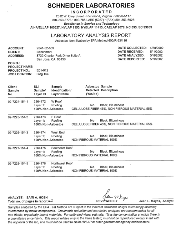
Bulk Sampling Protocol and Analytical Methods
Bulk samples of suspect asbestos containing building materials were obtained using standard industrial hygiene techniques including wetting the material to minimize fiber release. Our personnel wore half-face air purifying respirators equipped with high efficiency particulate (HEPA) filters while obtaining samples
Our sampling strategy for suspect friable surfacing materials was based on the guidelines outlined in the EPA publication Asbestos in Buildings: Simplified Sampling Scheme for Friable Surfacing Materials, and the procedures outlined in 40 CFR 763, Subpart E (AHERA). For non-friable suspect materials, AHERA requires the building inspector to determine the appropriate number of samples to obtain and analyze. Usually one to three samples of non-friable materials are collected.
For each homogeneous material identified by visual inspection as suspect material, random samples are obtained. A single bulk sample is randomly selected from each homogeneous material for first-round testing. If the sample is positive, the remaining samples are not analyzed; if the sample is negative, the other samples are submitted for study. Every sample must be reported negative if the material is to be considered non-asbestos containing.
The bulk samples were delivered to an independent laboratory that participates in the bulk sample proficiency analysis program conducted by the United States Environmental Protection Agency and is accredited by the National Voluntary Laboratory Program (NVLAP). The samples were analyzed using Polarized Light Microscopy (PLM) with dispersion staining to estimate the percent of asbestos composition by volume. Samples with no observable asbestiform minerals are designated as None-Detected. Samples in which asbestiform minerals are observed, but exist in concentrations of less than one percent (<1%), are designated as present in Trace amounts; all other samples are designated as asbestos containing with the appropriate percent of asbestos noted.
Appendix C
Laboratory Bulk Sampling Reports
Appendix D
Summary of Regulatory Requirements
Appendix D Summary of Regulatory Requirements
This appendix provides a summary of building owner and manager requirements under various asbestos regulations promulgated by the Occupational Safety and Health Administration (OSHA) and the Environmental Protection Agency (EPA) to protect building occupants and employees from exposure to asbestos.
Survey Requirements
Prior to any renovation activity, OSHA and EPA regulations require that a complete asbestos survey be performed to determine if asbestos is present in any suspect asbestos containing material that will be present in the construction or work area. This survey report addresses accessible materials. It is recommended that prior to renovation activities, inaccessible areas that could contain asbestos materials be inspected.
Notification and Posting Requirements
Regulatory agencies feel that the building owner or manager should be responsible for knowing and communicating the locations of asbestos in their buildings to building employees, outside contractors and tenants to prevent exposure to asbestos.
Under the California Health and Safety Code, building owners and managers are required to provide annual notifications regarding known asbestos containing materials in their buildings to building employees, tenants, vendors and outside contractors. Therefore, specific information contained in this survey report is required to be included in the notification.
OSHA requires building employees, outside contractors, vendors and construction contractors bidding on or performing work in buildings be provided with notification regarding asbestos containing materials in their work areas. OSHA also requires that asbestos warning signs be posted in mechanical rooms.
Removal Requirements
Under EPA regulations, asbestos containing materials must be properly removed by licensed asbestos abatement contractors prior to renovation or demolition activities that would disturb friable materials or cause non-friable materials to become friable and a regulated material.
Repair of Damaged Materials and Cleanup of Debris
OSHA requires that asbestos containing debris be immediately cleaned up. It is recommended that damaged materials that may release fibers be repaired as soon as possible o prevent fiber release and potential exposures.
Training Requirements
OSHA requires employers whose employees are likely to or required to disturb asbestos to receive an asbestos training course. Refresher training is required to be provided annually.
Appendix E
AHERA Building Inspector Certifications
Appendix F
Drawings Indicating Sampling Locations
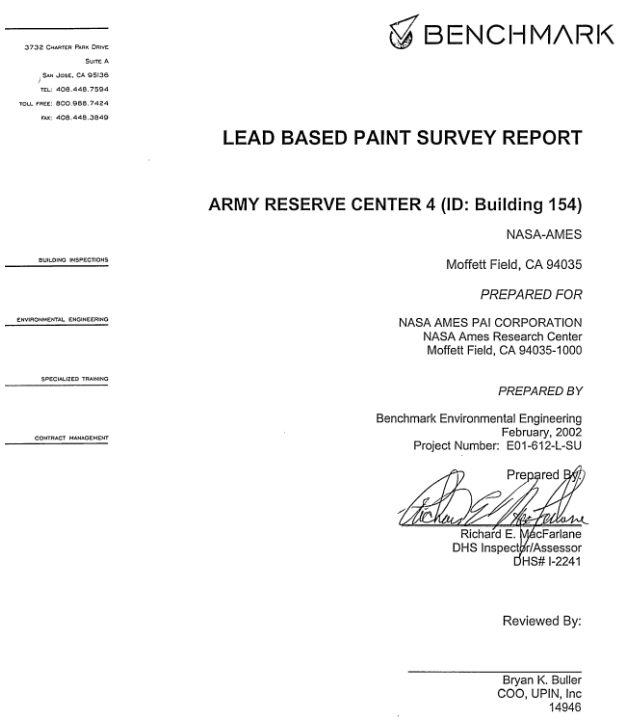
Section
Executive Summary
| 1 | Introduction |
| 2 | Scope of Services |
| 3 | Methodology |
| 4 | Findings and Observations |
Appendices
| A | XRF-Data Results Tables |
| B | Certification(s) |
1
EXECUTIVE SUMMARY
Benchmark Environmental Engineering was retained by PAI Corporation, to conduct a lead-based paint survey at Building located at Xxxxxxx Field, California.
In order to determine if lead based paint was present, 188 assays were taken using an X-RAY FLUORESCENCE (XRF) instrument. The results indicated that the following building components were above the EPA and OHS level of 1.0 mg/ cm2 or 5000 PPM.
Lead-based Paint was identified on the following building components:
Exterior:
| • | Door Frame, Fixed Window Panel, Window Sill, Stair Riser. |
Interior:
| • | Basement Stairwell - Handrail. |
| • | Stairwell at Room 121 - Door Frame. |
2
INTRODUCTION
Benchmark Environmental Engineering was retained by Xx. Xxxx XxXxxxxxxx, to conduct a lead-based paint survey at NASA Xxxx-XXX Corporation, Xxxxxxx Field, California.
Authorization to perform this survey was received via signed agreement to BENCHMARK from Xx. Xxxx XxXxxxxxxx, on or about August 1, 2001, as referenced by XXXXXXXXX’S proposal E01-612.
BACKGROUND
This structure is a two-story facility with a basement. It was built in 1953. The construction is concrete over a concrete foundation and with a flat composite roof.
WARRANTY
Benchmark Environmental Engineering warrants that the findings contained herein have been prepared with the level of care and skill exercised by experienced and knowledgeable environmental consultants who are appropriately licensed or otherwise trained to perform lead-related construction risk assessments and inspections pursuant to the scope of work required on this Project.
The survey included inspection of accessible materials. BENCHMARK did not inspect or sample inaccessible areas such as behind walls or within ductwork, and did not dismantle any part of the structure to survey inaccessible areas. For the purpose of this warranty, inaccessible is defined as areas of the building that could not be tested (sampled) without destruction of the structure or a portion of the structure. Inaccessible materials that are not visible to Xxxxxxxxx’s inspectors are assumed to be lead containing.
Authorization to perform this survey was received by BENCHMARK from Xx. Xxxx XxXxxxxxxx, of The PAI Corporation, on August 1, 2001, as referenced by Xxxxxxxxx’s Proposal E01-612.
The survey was conducted in February of 2002. A comprehensive site survey was performed based on the building plan. All building components identified in the specifications that may contain lead-based paint/coating were targeted for testing. (Exterior and interior walls, exterior and interior windows, doors and numerous associated components).
Sampling protocol for identification of lead-based paint was in accordance with The U.S. Department of Housing and Urban Development (HUD) Guidelines for the Evaluation and Control of Lead-Based Paint Hazards in Housing, Chapter 7. All suspect lead-coated surfaces were identified by building, wall, and building component, as such each component had a unique identification number.
The report establishes lead concentrations in painted surfaces as a general guidance tool for the purpose of conducting demolition activities for Building 154.
A total of 188 XRF assays collected within this building.
3
SCOPE OF SERVICES
Benchmark recognized the scope of work for the NASA Xxxx-XXX Corporation, to be composed of a Lead Based Paint Inspection for the Army Reserve Center 4 (ID: Building 154). The survey consisted of testing for lead-base paint in general accordance with the U.S Department of Housing and Urban Development (HUD) guidelines for the evaluation and control of Lead-Based Paint Hazards in Housing, Chapter 7.
Certain building components that are adjacent to each other and not likely to have different painting histories have been grouped together into a single testing combination, as follows: Window Casings/Stops/Jambs/Aprons -Or- Door Jambs/Stops/Transoms/Casings and other door frame parts.
The following building components were inspected when applicable:
| • | Exterior Areas: |
| Walls |
Windowsills | |
| Doors |
Downspouts | |
| Building Trim |
Balusters | |
| Stair Risers |
Windows | |
| Stair Handrails |
Door Molding | |
| Window Screen |
Skylight | |
| Stair Handrail |
Support Pillar |
| • | Interior Areas: |
| Walls |
Windowsills | |
| Balusters |
Door Molding | |
| Ceilings |
Skylight | |
| Ceiling Molding |
Baseboards | |
| Electrical Box |
Chair Rail | |
| Windows |
Stair Treads | |
| Doors |
Stair Xxxxxxxx | |
| Ceiling Molding |
Floors | |
| Grates |
Support Beams | |
| Book Shelf |
Wainscot |
4
METHODOLOGY
GENERAL REFERENCES
Inspection, sampling, and assessment procedures were performed in general accordance with the guidelines published by The Department of Housing and Urban Development’s (HUD) 1995 Guidelines, Chapter 7. The survey consisted of three major activities: visual inspection, sampling, and analysis. Although these activities are listed separately, they are integrated tasks.
VISUAL INSPECTION
An inspector that is a Department of Health Services Certified Lead Inspector/ Risk Assessor performed the inspection. An initial building walkthrough was conducted to determine the presence of suspect materials that were accessible or exposed.
SAMPLING PROCEDURES
Following the walkthrough, the inspector selected samples areas of exposed or accessible materials identified as suspect LBP. EPA and HUD guidelines were used to determine the sampling protocol. Sampling locations were chosen to be representative of the homogeneous material.
X-RAY FLUORESCENCE (XRF) ANALYSIS
XRF instruments measure lead in paint by directing high energy X-rays and gamma rays into the paint, causing the lead atoms in the paint to emit X-rays which are detected by the instrument and converted to a measurement of the amount of lead in the paint. The EPA approved technology allows for measurement of X-rays without scraping or samples preparation to characterize substrate or matrix effects. The Spectrum Analyzer, Metals Analysis Probe (MAP 4) is combined with a microprocessor system that enables field-testing with a high degree of quality control and speed. Sample locations, descriptions, conditions, and measurement results are automatically recorded by the instrument and easily downloaded to a PC or laptop.
QUALITY CONTROL PROGRAM
Benchmark Environmental Engineering utilizes only OHS approved inspectors, which are certified to use radioactive instruments. The MAP 4 Spectrum Analyzer has on-board calibration routines, which continuously operate, and self-correct to minimize sampling error. This is known as substrate correcting software.
5
FINDINGS AND OBSERVATIONS
LEAD
A total of 188 assays were taken. The results indicated that seven (?)assays contained lead above the EPA and OHS level of 1.0 mg/ cm2 or greater. The components, which contain lead-based paint, are:
Exterior:
| • | Door Frame, Fixed Window Panel, Window Sill, Stair Riser. |
Interior:
| • | Basement Stairwell - Handrail. |
| • | Stairwell at Room 121 - Door Frame. |
Cal/OSHA’s Lead in Construction Standard, Title 8, CCR section 1532.1, is primarily concerned with worker protection when disturbing any detectable level of lead in paint or surface coatings.
Assays with results less than 1.0 mg/cm2 and paint chip samples with results less than 5000 ppm may create hazardous conditions if subjected to poor and/or prohibited work practices. Refer to Work Activities on the following page.
OSHA LEAD REGULATION SUMMARY
The Federal Occupational Safety and Health Administration (OSHA) has enacted an interim lead standard, which was adopted by Cal/OSHA as 8 CCR 1532.1. The purpose of both standards is to protect construction workers from exposure to lead. OSHA is primarily concerned with activities that disturb lead-containing material. Lead was used in most paints until the mid 1950’s and was banned in amounts in excess of 0.06% by weight in 1978 for most non-industrial paints by the Consumer Product Safety Commission (CPSC).
The new standard requires contractors and employers who perform activities that would disturb lead, must monitor their employees to determine whether they are being exposed in excess of the Action Level (AL) of 30 micrograms per cubic meter of air (ug/m3) over an eight-hour time weighted average (TWA) or the Permissible Exposure Limit (PEL) of 50 ug/m3 TWA. Monitoring is performed by personal exposure air sampling.
Even when concentrations are below the AL, an employer must provide employees with High Efficiency Particulate Air (HEPA) filtered vacuums, wetting agents and hand-washing facilities. If the exposure exceeds the AL or the PEL, other procedures such as containing the area, decontamination facilities and medical monitoring are required.
OSHA has identified several activities that pose varying levels of potential lead exposure to laborers disturbing lead-containing paint. Estimated exposure levels of lead are founded on the activity itself, rather than the concentrations of lead present in paint. Therefore, as an
6
example, paints that contain 0.5% versus 15% of lead by weight or 0.8 mg/cm2 versus 3.5 mg/cm2 of lead in paint could present the same levels of potential exposure to workers depending on the activities that cause the disturbance and the administrative and engineering controls that are followed.
The following is a summary of work activities that disturb paint, the expected exposures and the respiratory protection requirements as outlined in the OSHA standards:
| Class I Activities: |
||
| Class I activities include: | Manual demolition, manual scraping, manual sanding, heat gun application, general cleanup, power tool cleaning with dust collection systems and spray painting activities. | |
| Potential Exposure: | 50 ug/m3 to 500 ug/m3 Minimum Respiratory Protection: Half mask air purifying respirator equipped with HEPA filters having a protection factor of 10. | |
| Class II Activities: |
||
| Class II activities include: | Using lead-containing mortars, lead burning, lead riveting, rivet busting, power tool cleaning without dust collection systems, cleanup of dry expendable abrasives and abrasive blasting. | |
| Potential Exposure: | 500 ug/m3 to 2,500 ug/m3
Minimum Respiratory Protection: Full face powered air-purifying respirators equipped with HEPA filters having a protection Factor of 100. | |
| Class III Activities: |
||
| Class III activities include: | Abrasive blasting, welding, cutting and torch burning on steel structures. | |
| Potential Exposure: | Greater than 2,500 ug/m3. Minimum Respiratory Protection: Full face supplied - air respirator operated in pressure demand mode or - the positive pressure mode. | |
DOSH 8 CCR 1532.1 requires that an initial exposure assessment be performed if workers will be performing any of the trigger tasks found in 1532.1. It should be noted that the California Department of Health Services (OHS) has issued emergency work procedures for lead paint materials that in the absence of any other procedures are recommendations.
7
The following recommendations are general site specific work practice specifications.
| • | You must use “containment” when you sand, scrape, or disturb any detectable level of lead in paint or surface coatings. |
| • | Containment is required for abatement and/or any activity that or disturb any detectable level of lead in paint or surface coatings. |
| • | You must be OHS-certified (workers, supervisors, monitors, and inspectors) if you are conducting abatement. |
| • | You must follow an abatement plan. |
| • | A OHS -certified supervisor, monitor, and/or project designer must design an abatement project. |
| • | A clearance inspection by dust wipe sampling is required for abatement. |
LEAD WASTE DISPOSAL
The visual determination indicated that all building components that tested positive were in intact to poor condition (minor cracking to flaking and peeling). As such, these components need to be considered a lead hazard if flaking paint is not stabilized. All small debris (paint chips, rags, filters, and components smaller that 2”x2”) that may be generated during the paint stabilization process (paint preparation) should be considered Class I, lead hazardous waste. The debris generated from paint stabilization of LBP building components should be segregated from all other dust and debris. Building components, which tested positive, should be stabilized by a OHS-accredited Contractor.
Power washing may be conducted on the building. Run off water must be collected and analyzed by an accredited laboratory to meet the criteria established by the Clean Water Act, Resource Conservation and Recovery Act (RCRA 1972). Lead levels must not exceed 5mg/L.
8
CODES AND REGULATIONS - LEAD-BASED PAINT
Federal and state regulations, which govern lead-based, paint work or hauling and disposal of lead-based paint waste materials include but are not limited to the following:
FEDERAL
Housing and Urban Development (HUD) 1995 Guidelines For The Evaluation and Control of Lead-Based Paint in Housing
OSHA
Lead In Construction
29 CFR 1926.62
NESHAP
Emissions Standards
40 CFR 50.12
Lead-Based Paint Poisoning Prevention Act (LBPPPA), 1970.
Title 10 - Residential LBP Hazard Reduction Act, 1992, (amendment for LBPPPA, 1970)
Resource Conservation Recovery Act (RCRA)
STATE
Cal/OSHA
Lead In Construction
Title 8 CCR 1532.1
Department of Health Services (DHS)
Emergency Work Practice Regulations
Title 17 CCR, Division 1, Chp.
9
APPENDIX A
XRF - DATA RESULTS TABLE
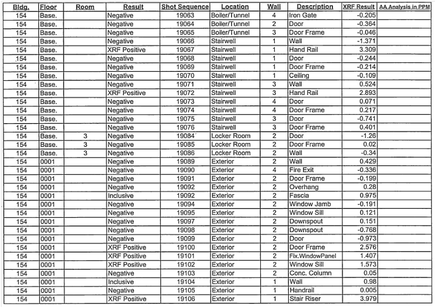
| Bldg. 154 - Lead | Confidential | Page 1 |
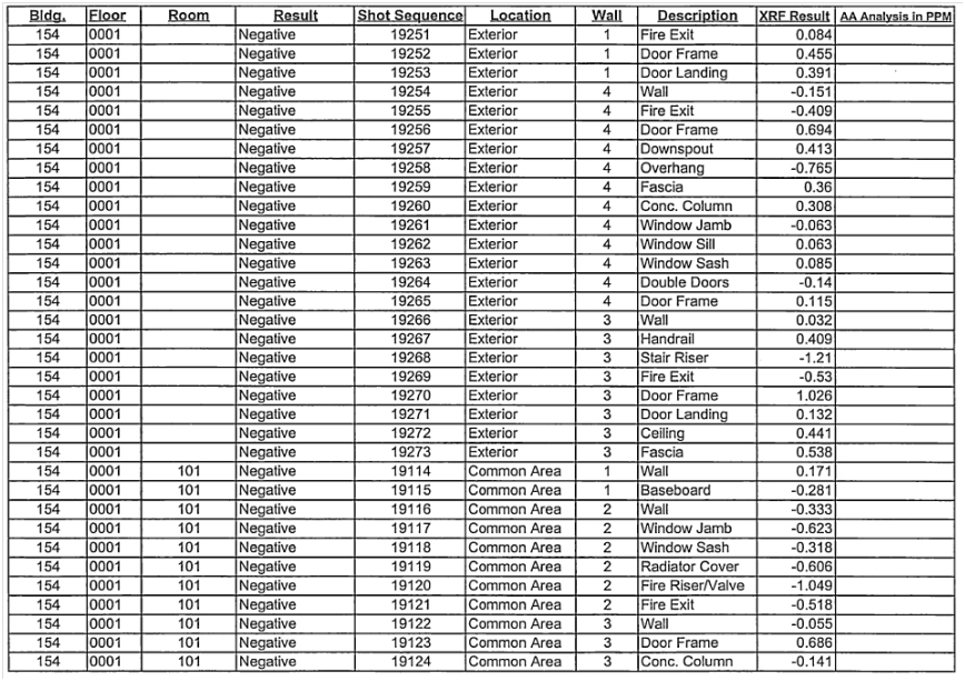
| Bldg. 154 - Lead | Confidential | Page 2 |
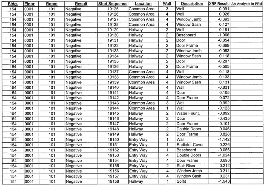
| Bldg. 154 - Lead | Confidential | Page 3 |
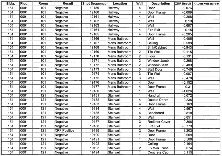
| Bldg. 154 - Lead | Confidential | Page 4 |
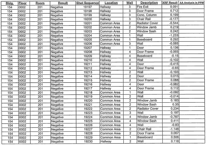
| Bldg. 154 - Lead | Confidential | Page 5 |
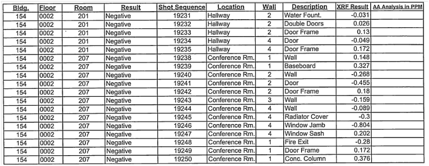
| Bldg. 154 - Lead | Confidential | Page 6 |
APPENDIX 8
CERTIFICATION(S)
THIRD AMENDMENT TO NASA XXXX RESEARCH
CENTER ENHANCED USE LEASE
This Third Amendment to NASA Xxxx Research Center Enhanced Use Lease of Historic Property (the “Amendment”) is made as of August 17, 2016, by and between THE NATIONAL AERONAUTICS AND SPACE ADMINISTRATION, an Agency of the United States of America, acting by and through Xxxx Research Center (“Landlord”), and BLOOM ENERGY CORPORATION, a Delaware corporation (“Tenant”), with reference to the following facts:
X. Xxxxxxxx and Xxxxxx entered into that certain NASA Xxxx Research Center Enhanced Use Lease, dated as of December 5, 2011 (SAA2 – 402658), as amended (collectively, the “Original Lease”). The current Expiration Date under the Original Lease is December 31, 2016. Each capitalized term used in this Amendment, but not defined herein, shall have the meaning ascribed to it in the Original Lease.
B. Tenant desires to continue to lease the Premises, and has requested to extend the Term for an additional one (1) year, and to have the right to request a further extension of the Term for an additional one (1) year. Xxxxxxxx is willing to amend the Original Lease on the terms and conditions of this Amendment.
NOW, THEREFORE, the parties agree as follows:
1. Amendments of the Original Lease. Effective as of January 1, 2017 (the “Effective Date”), the parties hereby agree that the Original Lease is amended as follows.
(a) The Basic Lease Information attached to the Original Lease is hereby deleted and replaced in its entirety with the Basic Lease Information attached to this Amendment as Exhibit I. Among other things, the amended Basic Lease Information sets forth a new Expiration Date of December 31, 2017, and reflects the amount of monthly Gross Rent as of the Effective Date.
(b) The following language is hereby added as section 2.1(b) to the Original Lease as follows:
“(b) Provided that (i) no Event of Default (as defined in section 10.1) has occurred and no event has occurred which, with the passage of time, the giving of notice, or both, would constitute an Event of Default, and (ii) Landlord, in its sole and absolute discretion, consents in writing, then Tenant shall have the right to extend the Term for up to one (1) additional period of one (1) year on and subject to the following terms and conditions. Tenant may exercise such right to extend the Term only by delivering written notice to Landlord of Tenant’s election to extend the Term at least ninety (90) days before the then – current expiration of the Term. Upon Xxxxxxxx’s receipt of any such notice, Landlord shall promptly consider Xxxxxx’s request and deliver to Tenant written notice granting or withholding Landlord’s consent in Xxxxxxxx’s sole and absolute discretion; provided, however, if Landlord fails to deliver to Tenant any such
| XXXXX XXX 3rd Amend Final 8.17.16 | SAA2 - 402658 |
notice on or before the date that is forty – five (45) days before the then – current expiration of the Term, then Landlord shall be conclusively deemed to have withheld its consent and the Term shall expire on the then – current Expiration Date. If the Term is duly extended in accordance with this section 2.l (b), Tenant shall continue to occupy the Premises on all of the other terms and conditions of this Lease. In no event shall the Term extend beyond December 31, 2018.”
(c) Section 14.2 of the Original Lease is hereby deleted and replaced in its entirety with the following language:
“14.2 Close Calls and Mishaps.
(a) For purposes of this Lease, the following terms shall have the following meanings: (i) “Close Call” shall mean an event in which there is no injury or only minor injury requiring first aid and/or no equipment or property damage, or minor equipment or property damage of less than $20,000, or not injury or only minor injury requiring first aid, but which possesses a potential to cause a Mishap (as defined below); and (ii) “Mishap” shall mean an unplanned event that results in at least one of the following: (a) injury to non-Landlord personnel, caused by Landlord operations; (b) damage to public or private property (including foreign property), caused by Landlord operations or Landlord-funded development or research projects; (c) occupational injury or occupational illness to Landlord personnel; (d) Landlord mission failure before the scheduled completion of the planned primary mission; (e) destruction of, or damage to, Landlord property except for a malfunction or failure of component parts that are normally subject to fair wear and tear and have a fixed useful life that is less than the fixed useful life of the complete system or unit of equipment, provided that the following are true: (1) there was adequate preventative maintenance; and (2) the malfunction or failure was the only damage and the sole action is to replace or repair that component. If, in Xxxxxx’s discretion, Xxxxxx believes that a Close Call or Mishap may become highly visible outside of Tenant’s organization (such as by the media or a governmental agency), then Tenant shall promptly notify Landlord by telephoning the NASA Xxxx Safety, Health and Medical Services Division at 650 – 604 – 5602.
(b) In addition, Tenant shall notify both the Occupational Safety and Health Administration (“OSHA”) by telephoning the area office nearest the site of the Mishap or OSHA’s toll-free number, 800 – 321 – 6742 and the NASA Xxxx Safety, Health and Medical Services Division at 650 – 604 – 5602 within the following timeframes:
| Incident Type |
Timeframe Requirement for Reporting Incidents Directly to OSHA |
Requirement for Reporting Incidents to Landlord’s Safety, Health, and Medical Services Division | ||
| 1 or more work-related fatalities | Within 8-hours | As Soon as Possible | ||
| 3-work-related in-patient hospitalizations | Within 24-hours | As Soon as Possible | ||
| 1 or 2 - work-related in-patient hospitalizations | Within 24-hours | As Soon as Possible | ||
| Amputations | Within 24-hours | As Soon as Possible | ||
| Employee’s loss of an eye | Within 24-hours | As Soon as Possible |
| XXXXX XXX 3rd Amend Final 8.17.16 | SAA2 - 402658 |
2
(c) The Director of NASA Xxxx Research Center reserves the right to investigate any Mishap in accordance with Landlord’s policies and procedures.”
(d) The site plan outlining the building Premises attached to the Original Lease as a portion of Exhibit A is hereby deleted and replaced in its entirety with the site plan outlining the building Premises attached to this Amendment as Exhibit 2. Exhibit A-1 remains unchanged.
(e) The List of Environmental Reports attached to the Original Lease as Exhibit D is hereby deleted and replaced in its entirety with the List of Environmental Reports attached to this Amendment as Exhibit 3.
2. No Other Amendment; Conflicts. Except as set forth in this Amendment, the provisions of the Original Lease remain in full force. If the provisions of this Amendment conflict with the provision§·of the Original Lease, then the provisions of this Amendment shall prevail.
IN WITNESS WHEREOF, Landlord and Xxxxxx have executed this Amendment as of the date first written above.
| Tenant: | Landlord: | |||||||
| BLOOM ENERGY CORPORATION, a | NATIONAL AERONAUTICS AND SPACE | |||||||
| Delaware corporation | ADMINISTRATION, an Agency of the United States | |||||||
| By | /s/ Xxxxx Xxxx |
By | /s/ Xxxxxx X. Xx | |||||
| Xx. Xxxxxx X. Xx | ||||||||
| Chief Financial Officer | Director, Xxxx Research Center | |||||||
| XXXXX XXX 3rd Amend Final 8.17.16 | SAA2 - 402658 |
3
EXHIBIT 1 TO THIRD AMENDMENT
NASA XXXX RESEARCH CENTER
ENHANCED USE LEASE
Amended Basic Lease Information
Date: August 17, 2016.
Landlord: NATIONAL AERONAUTICS AND SPACE ADMINISTRATION, an Agency of the United States, Xxxx Research Center located at Xxxxxxx Field, California.
Tenant: BLOOM ENERGY CORPORATION, a Delaware corporation.
Premises (section 1.1): (a) The parcel of real property outlined in Ex hi b i t A, containing approximately 73,939 square feet (more or less) of land area, including Parcel B543 (containing approximately 29,760 square feet, including square footage under Building 543); Building 543(containing approximately 9,166 square feet (more or less) of lab space and 3,375 square feet of a new building constructed by Tenant (the “Additional Building”); and 44, 179 square feet of additional land (together, the “Building 543 Premises”); and (b) all of the space in Building 154 (“Building 154”) outlined in Exhibit A-1 containing approximately 14,359 square feet (more or less) of building area (the “Building 154 Premises”). The Building 543 Premises and the Building 154 Premises are located at NASA Xxxx Research Center, Xxxxxxx Field, California. A site plan showing the locations of the Building 543 Premises and the Building 154 Premises is attached hereto as Exhbit A. Building 543 and Building 154 are individually referred to herein as a “Building” and are collectively referred to herein as the “Buildings.”
Property (section 1.1): The land, the buildings and other improvements known as NASA Xxxx Research Center, Xxxxxxx Field, California 94035-1000.
Term (section 2.1): Six (6) years, subject to the right to extend the Term in accordance with section 2.1(b).
Commencement Date (section 2.1): December 16, 2011.
Expiration Date (section 2.1): December 31, 2017.
Monthly Base Rent (dollars per month) (section 3.1): $43,772.19, including $13,199.04 (based on $1.44 per square foot per month for the portion of Building 543 containing 9, 166 square feet of lab space); $1,215.00 (based on $0.36 per square foot per month for the portion of Building 543 containing the Additional Building); $8,394.01 (based on $0.19 per square foot per month for 44, 179 square feet of additional land surrounding Building 543); and $20,964.14 (based on $1.46 per square foot per month for office space in Building 154). The fair market value of Parcel B543 containing 29,760 square foot is included in the Monthly Base Rent for Building 543.
Security Deposit (section 3.3): $40,500.00.
| XXXXX XXX 3rd Amend Final 8.17.16 | SAA2 - 402658 |
| Rent Payment Address (section 3.7): | NASA Shared Service Center (NSSC)- | |
| FMD Accounts Receivable | ||
| Attn: For the Accounts of Xxxx Research Center | ||
| (Agreement #SAA2-402658) | ||
| Bldg. 0000, X Xxxx | ||
| Stennis Space Center, MS 39529 |
Permitted Use of the Premises (section 4.1): Bloom Energy will use and occupy the Building 543 Premises solely for research and development, and testing, including as its research laboratory and to test its products. Bloom Energy will use and occupy the Building 154 Premises solely for office purposes; provided, however, Bloom Energy may use rooms 124, 125, 126, 128, 129 and 130 for minor assembly of wiring harnesses and piping.
| Landlord’s Address (section 14.1): | NASA Xxxx Research Center | |
| Xx. Xxxxxxx X. Xxxxxx, Mail Stop 204 – 2 Bldg. 204, Rm 215 | ||
| P.O. Box 1 | ||
| Xxxxxxx Field, CA 94035-0001 | ||
| Tenant’s Address (section 14.1): | Bloom Energy Corporation | |
| 0000 Xxxxxxx Xxxxx | ||
| Sunnyvale, CA 94089 Attn: Xx. Xxxxx Xxxx | ||
Exhibit A – Site Plan; Plan Outlining the Building 543 Premises
Exhibit A-1 – Plans Outlining the Building 154 Premises
Exhibit B – Description of the TI Work
Exhibit C – Support Agreement
Exhibit D – List of Environmental Reports
The foregoing Basic Lease Information is incorporated in and made a part of the Lease to which it is attached. Ifthere is any conflict between the Basic Lease Information and the Lease, the Basic Lease Information shall control.
| Tenant: | Landlord: | |||||||
| BLOOM ENERGY CORPORATION, a | NATIONAL AERONAUTICS AND SPACE | |||||||
| Delaware corporation |
ADMINISTRATION, an Agency of the United States | |||||||
| By | /s/ Xxxxx Xxxx |
By | /s/ Xxxxxx X. Xx | |||||
| Xx. Xxxxxx X. Xx | ||||||||
| Chief Financial Officer |
Director, Xxxx Research Center | |||||||
| XXXXX XXX 3rd Amend Final 8.17.16 | SAA2 - 402658 |
II
EXHIBIT 2 TO THIRD AMENDMENT
Revised Site Plan; Plan Outlining the Building 543 Premises
(Supersedes Exhibit A to Original Lease)
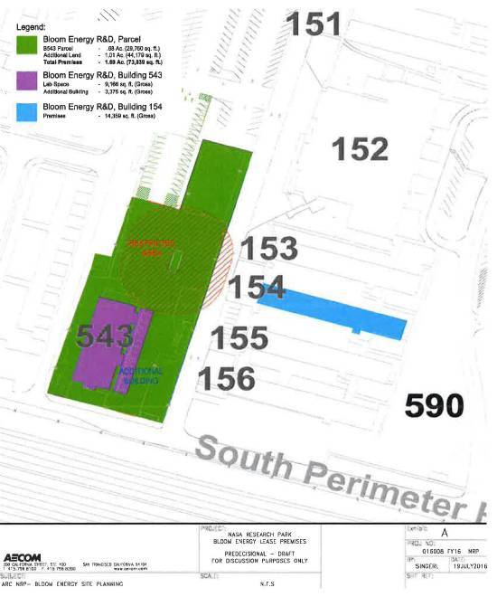
| XXXXX XXX 3rd Amend Final 8.17.16 | SAA2 - 402658 |
iii
EXHIBIT 3 TO THIRD AMENDMENT
Revised Li st of Environmental Reports
(Supersedes Exhibit D to Original Lease)
Revised Human Health Risk Assessment for NASA Research Park
Environmental Issues Management Plan
Lead Impacted Soil Summary Report and Sampling and Removal Action Work Plan
Environmental Baseline Survey – Parcel 5
Building 543 Premises
Closure Plan 5
1994 Asbestos Survey of Bldg. 543
Bldg. 543 Asbestos / Lead and Mold Investigation 2001
Bldg. 543 Asbestos Sampling 2009
Build i ng l54 Premises
Bldg 154 Asbestos / Lead Investigation 2002
1994 Asbestos Survey of Bldg. 154
Bldgs 153, 154, 155, 156 Asbestos / Lead Visible Mold Investigation 2002
Bldg. 154 Asbestos Sampling 2010
| XXXXX XXX 3rd Amend Final 8.17.16 | SAA2 - 402658 |
iv
SUPPORT AGREEMENT
| 1. AGREEMENT NUMBER (Provided DV Supplier) SAA2-402658 |
2. SUPERSEDED AGREEI’IENT NO. | 3. EFFECTIVE DATE
October 1, 2016 |
|
4. EXPIRATION DATE (Mav be ‘Indefinite”) September 30, 2017 | ||||||
| !l. SUP PLYING ACTIVITY | 6. RECEIVING ACTIVITY | |||||||||
| a. NAME AND ADDRESS
National Aeronautics and Space Administration Xxxx Research Center Xxxxxxx Field, CA 94035-1000
NRP Business Development Specialist: Xxxxxxx Carbon-Xxxxxx |
x. XXXXXX AND ADDRESS
Bloom Energy Corporation 0000 Xxxxxxx Xxxxx Xxxxxxxxx, XX 00000 Attn: Xx. Xxxxx Xxxx | |||||||||
| b. MAJOR COMMAND
NASA HQ, Science Mission Directorate, Washington D.C. |
b MAJOR COMMAND | |||||||||
| 7. SUPPORT PROVIDED BY SUPPLIER | ||||||||||
| a SUP PORT (Specify wna. wnen, Where, and how much)
Modified Net Rent
|
b. BASIS FOR REIMBURSEMENT | c ESTIMATED REIMBURSEMENT | ||||||||
| From 10/01116 - 12/31116: | ||||||||||
| Bldg. 543 Premises (9, 166 sf @ $1 08 sf/mo) | Market comps | $ | 29,697.84 | |||||||
| Bldg, 543 Additional Lan d Area (44,179 sf @ $0 19 sf/mo) | Market comps | $ | 25,182.03 | |||||||
| Bldg. 154 (14,359 sf @ $1.10 sf/mo) | Market comps | $ | 47,384.70 | |||||||
| B543 Addition | $ | - 0 - | ||||||||
| Sub Total | $ | 102,264.57 | ||||||||
| From 01/01117 - 09/31117 (3% CPI Increase begins) | ||||||||||
| Bldg. 543 Premises (9, 166 sf @ $1 11 sf/mo) | $ | 91,568.34 | ||||||||
| Bldg. 543 Additional Lan d Area (44, 179 sf @ $0 20 sf/mo) | $ | 79,522.20 | ||||||||
| Bldg. 154 (14,359 sf @ $L13 sf/mo) | $ | 146,031.03 | ||||||||
| B543 Addition | - 0 - | |||||||||
|
|
|
|||||||||
| Sub Total | $ | 317, 121 57 | ||||||||
| Institutional Services Pool ($0.39 sf/mo) | $ | 42,896.88 | ||||||||
| Bldg 543 Premises (9, 166 sf) | $ | - 0 - | ||||||||
| Bldg. 543 Additional Land Area (44, 179 sf) | $ | 67,200 12 | ||||||||
| Bldg 154 (14,359 sf) | $ | 15,79500 | ||||||||
|
|
|
|||||||||
| Bldg. 543 Addition (3,37 5 sf) | $ | 125,892.00 | ||||||||
| Demand Services (Due in Advance Quarterly): | ||||||||||
| - Utilities Metered, Bldgs 543 & 154 (based on FY16 actual) | Actual Cost | $ | 315,000.00 | |||||||
| - Facilities | Estimate | $ | 2,000 00 | |||||||
| Grand Total | $ | 862,278.14 | ||||||||
| Security Deposit | Paid in FYJ 2, carryover into FY17 | $ | 40,500 00 | |||||||
| ADDITIONAL SUPPORT REQUIREMENTS ATTACHED: D Yes | D No | |||||||||
| 8. SUPPLYING COMPONENT | 9. RECEIVING COMPONENT | |||||||||
| a. COMPTROLLER SIGNATURE n/a |
b DATE SIGNED n/a |
a. COMPTROLLER SIGNATURE n/a |
|
b. DATE SIGNED n/a | ||||||
| c. APPROVI NG AUTHORITY | c. APPROVINGAUTHORITY | |||||||||
| (1) Typed Name Xxxx Xxxxx |
(11 Typed Name Xxxxx Xxxx, Ch ief Financial Officer | |||||||||
| (21 Orqanization Chief Financial Officer |
(3) Telephone Number (000) 000-0000 |
(2) Orqanizalion Bloom Energy Corporation |
(3) Telephone Number | |||||||
| (4) Siqnature | (5) Date Siqned | (4) Signatures: /s/ Xxxxx Xxxx | 10/19/2014 | |||||||
| 10. TERMINATI ON (Complete only when agreement is terminated prior to scheduled expiration date.) J/ | r | |||||||||
| a APPROVING AU THORITY SIGNATURE | b. DATE SIGNED | a. APPROVING AU THORITY SIGNATURE | b DATE SIGNED | |||||||
| DD FORM 1144, NOV2001 | PREVIOUS EDITIONS MAY BE USED | Page 1 of 3 | ||||||||
September 12, 2017
Xx. Xxxxx Xxxx
Chief Financial Officer
Bloom Energy Corporation
0000 Xxxxxxx Xxxxx
Sunnyvale, CA 94089
Dear Xx. Xxxx:
In response to your request to extend the term of the 3rd Amendment to the Enhanced Use Lease of Historic Property, SAA2-402658, dated August 17, 2016; this letter serves as NASA Xxxx Research Center’s approval to extend the term for one year (currently expiring December 31, 2017).
Notwithstanding your failure to request the extension in accordance with Section 2.1 (b), we hereby approve the request and agree to the extension on all of the terms and conditions of the Lease.
This letter confirms that you continue to desire to extend the term and agree to perform your obligations under the Lease through December 31, 2018.
We look forward to a continual working relationship with Bloom Energy.
| Sincerely,
|
| /s/ Xxxxxxx Carbon-Xxxxxx |
| Xxxxxxx Carbon-Xxxxxx |
| NRP Account Manager |
CC:
ARC/DT/204-2/X. Xxxxxx
ARC/DL/202A-4/X. Xxxxxx

