TEXT

TABLE
OF CONTENTS
TEXT
|
1.0
|
Summary
|
1
|
|
1.1
|
Introduction
|
1
|
|
1.2
|
Property
Exploration
|
2
|
|
1.3
|
Geological
Setting
|
2
|
|
1.4
|
▇▇▇▇▇▇
Project - Geology, Alteration, and Mineralization
|
3
|
|
1.5
|
Mineral
Resource Estimation
|
3
|
|
1.6
|
Conclusions
|
5
|
|
1.7
|
Recommendations
|
6
|
|
2.0
|
Introduction
and Terms of Reference
|
8
|
|
2.1
|
Introduction
|
8
|
|
2.2
|
Terms
of Reference
|
8
|
|
3.0
|
Disclaimer
|
9
|
|
4.0
|
Property
Description and Location
|
10
|
|
4.1
|
Location
|
10
|
|
4.2
|
Land
Status and Agreements
|
11
|
|
4.2.1
|
▇▇▇▇▇▇
Mining Company Agreement
|
12
|
|
4.2.2
|
Underlying
Agreements - Unpatented Federal Mining Claims
|
15
|
|
4.2.2.1
|
BEE
DEE group
|
15
|
|
4.2.2.2
|
▇.
▇. ▇▇▇▇▇ Unpatented Claims
|
15
|
|
4.2.2.3
|
VEK/▇▇▇▇▇▇
Unpatented Claims
|
15
|
|
4.2.3
|
Underlying
Agreements - Patented Fee Lands
|
16
|
|
4.2.3.1
|
▇▇▇▇▇▇▇▇▇▇,
et al Lease
|
16
|
|
4.2.3.2
|
▇.
▇▇▇▇▇ Lease
|
16
|
|
4.2.3.3
|
▇▇▇▇▇▇
Lease
|
16
|
|
4.2.4
|
Underlying
Agreements - Other Agreements
|
16
|
|
4.2.4.1
|
▇▇▇▇▇▇▇▇▇▇
- Seven Dot Agreement
|
17
|
|
4.2.4.2
|
▇▇▇▇▇▇▇
(Glamis Gold) Acquisition
|
17
|
|
4.2.4.3
|
Cordilleran
Overriding Royalty
|
18
|
|
4.2.4.4
|
▇▇▇▇▇▇▇▇
Gold/Newmont Capital Overriding Royalty
|
18
|
|
4.2.4.5
|
Echo
Bay Lands
|
18
|
|
4.3
|
Royalty
Summary
|
18
|
|
5.0
|
Accessibility,
Climate, Local Resources, Infrastructure and Physiography
|
20
|
|
5.1
|
Accessibility
|
20
|
|
5.2
|
Climate
|
21
|
|
5.3
|
Local
Resources and Infrastructure
|
21
|
|
5.3.1
|
Background
|
21
|
|
5.3.2
|
Physical
Infrastructure
|
22
|
|
5.4
|
Adjacent
Operations
|
22
|
|
5.5
|
Physiography,
Flora, and Fauna
|
22
|
|
5.5.1
|
Physiography
|
22
|
|
5.5.2
|
Flora
|
22
|
|
5.5.3
|
Fauna
|
22
|
|
6.0
|
History
|
24
|
|
6.1
|
Summary
|
24
|
|
6.2
|
Initial
Discovery
|
24
|
|
6.3
|
Pre-1970
Development
|
24
|
|
6.4
|
Cordex
Syndicate Exploration and Development
|
24
|
|
6.5
|
▇▇▇▇▇▇
Mining Company Exploration and Development
|
25
|
|
6.6
|
Homestake-Barrick
Exploration
|
25
|
|
6.7
|
▇▇▇▇▇▇
Project Production Summary
|
25
|
|
6.8
|
Atna
Resources Exploration
|
25
|
|
7.0
|
Geological
Setting
|
26
|
|
7.1
|
Regional
Setting
|
26
|
|
7.2
|
▇▇▇▇▇▇
Mine Setting
|
30
|
|
8.0
|
Deposit
Type
|
34
|
|
8.1
|
Sediment-hosted,
▇▇▇▇▇▇-type Gold System
|
34
|
|
9.0
|
Mineralization
|
36
|
|
9.1
|
Host
Rocks
|
36
|
|
9.2
|
Alteration
|
37
|
|
9.3
|
Mineralized
Zone Configuration
|
38
|
|
10.0
|
Exploration
|
42
|
|
10.1
|
Introduction
|
42
|
|
10.2
|
Geologic
Mapping and Geochemical Sampling
|
42
|
|
10.3
|
Drilling
|
43
|
|
10.4
|
Trenching
and Channel Sampling
|
43
|
|
10.5
|
Geophysics
|
43
|
|
10.6
|
Underground
Drifting / Evaluation
|
44
|
|
11.0
|
Drilling
|
45
|
|
11.1
|
Summary
of Past and Present Programs
|
45
|
|
11.1.1
|
Drilling
by Earlier Operators
|
45
|
|
11.1.2
|
Drilling
by Atna Resources
|
45
|
|
11.2
|
Drilling
methods
|
46
|
|
11.2.1
|
Reverse
Circulation Rotary Drilling
|
47
|
|
11.2.2
|
Diamond
Core Drilling
|
48
|
|
11.3
|
Logging
|
48
|
|
11.3.1
|
Reverse
Circulation Rotary Chip Logging
|
48
|
|
11.3.2
|
Diamond
Drill Core Logging
|
48
|
|
12.0
|
Sampling
Method and Approach
|
50
|
|
12.1
|
Sampling
Methods
|
50
|
|
12.1.1
|
Reverse
Circulation Rotary
|
50
|
|
12.1.2
|
Diamond
Core Drilling
|
50
|
|
12.2
|
Sample
Quality - Recovery
|
50
|
|
12.2.1
|
Reverse
Circulation Rotary
|
50
|
|
12.2.2
|
Core
|
50
|
|
12.3
|
Sample
Interval
|
51
|
|
12.3.1
|
Reverse
Circulation Rotary
|
51
|
|
12.3.2
|
Core
|
51
|
|
12.4
|
Sample
Preparation, Quality Control Measures and Security
|
51
|
|
12.4.1
|
Sample
Preparation and Quality Control Measures - RC Rotary
Drilling
|
51
|
|
12.4.2
|
Sample
Preparation and Quality Control Measures - Core Drilling
|
52
|
|
12.4.3
|
Security
- Reverse Circulation and Core Samples
|
54
|
|
12.4.4.1
|
On-site
|
54
|
|
12.4.4.2
|
Laboratory
Sample Preparation
|
54
|
|
12.5
|
Certified
Standard Insertion
|
55
|
|
12.5.1
|
Protocol
|
55
|
|
12.5.2
|
Summary
of Results
|
56
|
|
12.6
|
Blank
Sample Insertion
|
59
|
|
12.6.1
|
Protocol
|
59
|
|
12.6.2
|
Summary
of Results
|
59
|
|
12.7
|
Duplicate
Samples - Reverse Circulation Rotary
|
60
|
|
12.7.1
|
Protocol
|
60
|
|
12.7.2
|
Summary
of Results
|
61
|
|
12.8
|
Check
Assays of Mineralized Samples
|
62
|
|
12.8.1
|
Protocol
|
62
|
|
12.8.2
|
Summary
of Results
|
62
|
|
12.9
|
Laboratory
Quality Assurance and Control
|
66
|
|
13.0
|
Data
Verification
|
68
|
|
13.1
|
Summary
|
68
|
|
13.2
|
Database
of Previous Drilling
|
68
|
|
13.2.1
|
Tables
|
69
|
|
13.2.2
|
Data
Corrections
|
69
|
|
13.2.3
|
General
description of pre Atna assay results and procedures.
|
71
|
|
13.3
|
Pulp
Selection
|
72
|
|
13.4
|
Re-Assay
Methods
|
73
|
|
13.4.1
|
Processing
by BSi Inspectorate
|
73
|
|
13.4.2
|
Processing
by ALS Chemex
|
73
|
|
13.5
|
Re-Assay
Results
|
74
|
|
13.6
|
Discussion
|
76
|
|
14.0
|
Database
Audit
|
78
|
|
14.1
|
Analytical
Data
|
78
|
|
14.1.1
|
Validation
Process
|
78
|
|
14.2
|
Drill-hole
Collar Location
|
79
|
|
15.0
|
Adjacent
Properties
|
80
|
|
15.1
|
Summary
|
80
|
|
15.2
|
▇▇▇▇▇▇
Mine
|
80
|
|
15.3.
|
▇▇▇▇▇▇▇▇/Turquoise
Ridge Mine Complex
|
80
|
|
15.3.1
|
History
|
80
|
|
15.3.2
|
Geologic
Setting
|
81
|
|
15.3.3
|
Gold
geology
|
81
|
|
15.4
|
Twin
Creeks
|
82
|
|
15.4.1
|
Physiography
|
82
|
|
15.4.2
|
Stratigraphy
|
83
|
|
15.4.3
|
Structure
|
83
|
|
15.4.4
|
Erosion
& Alluviation
|
84
|
|
15.4.5
|
Mineralization
|
84
|
|
15.4.6
|
Alteration
|
85
|
|
15.4.7
|
Summary
|
86
|
|
16.0
|
Mineral
Processing and Metallurgical Testing
|
87
|
|
17.0
|
Mineral
Resources Estimates
|
88
|
|
17.1
|
Introduction
|
88
|
|
17.2
|
Geologic
Model, Domains and Coding
|
89
|
|
17.2.1
|
Geologic
Model
|
89
|
|
17.2.2
|
Domains
and Coding
|
89
|
|
17.3
|
Available
Data
|
94
|
|
17.4
|
Compositing
|
96
|
|
17.5
|
Exploratory
Data Analysis
|
96
|
|
17.5.1
|
Basic
Statistics by Domain
|
97
|
|
17.5.2
|
Contact
Profiles
|
98
|
|
17.5.3
|
Histograms
and Log-Probability Plots
|
99
|
|
17.5.4
|
Conclusions
and Modeling Implications
|
103
|
|
17.6
|
Bulk
Density Data
|
103
|
|
17.7
|
Evaluation
of Outlier Grades
|
103
|
|
17.8
|
Variography
|
104
|
|
17.9
|
Model
Setup and Limits
|
105
|
|
17.10
|
Interpolation
Parameters
|
107
|
|
17.11
|
Validation
|
108
|
|
17.11.1
|
Visual
Inspection
|
108
|
|
17.11.2
|
Model
Checks for Change of Support
|
109
|
|
17.11.3
|
Comparison
of Interpolation Methods
|
111
|
|
17.11.4
|
Swath
Plots
|
112
|
|
17.12
|
Resource
Classification
|
114
|
|
17.13
|
Key
Assumptions of Economic and Technical Parameters
|
117
|
|
17.14
|
Mineral
Resources
|
118
|
|
18.0
|
Other
Relevant Data and Information
|
121
|
|
19.0
|
Interpretation
and Conclusions
|
123
|
|
20.0
|
Recommendations
|
124
|
|
20.1
|
Recommended
Program and Budget
|
125
|
|
References
|
128
|
FIGURES
|
Figure
4-1: Location Map of the ▇▇▇▇▇▇ Mine Project
|
11
|
|
Figure
4-2: Generalized Land Status Map
|
12
|
|
Figure
4-3: Detailed Land Status and Agreement Map
|
14
|
|
Figure
7-1: Regional Stratigraphy
|
27
|
|
Figure
7-2: Regional Geology
|
29
|
|
Figure
7-3: TectonoStratigraphy
|
30
|
|
Figure
7-4: Mine Site Geology
|
33
|
|
Figure
9-1: Grade-Thickness Long Section, CX Fault Zone
|
39
|
|
Figure
9-2: Grade-Thickness Long Section, Range Front Fault
Zone
|
41
|
|
Figure
12-1: Standards Run With Gravimetric Finish.
|
58
|
|
Figure
12-2: Standards Run With AA Finish
|
59
|
|
Figure
12-3: Comparison of Duplicate Samples Taken at the
Drill vs. Assay
Sample.
|
62
|
|
Figure
12-4: Sample Variance of All Check Samples
|
63
|
|
Figure
12-5: X-Y Pair Plot of Check vs. Original Assay,
By Grade
|
64
|
|
Figure
12-6: Variance of AA-Finish samples < 3000 ppb
|
65
|
|
Figure
12-7: Gravimetric Finish Comparisons - -Check Assays
to Original
Assays
|
66
|
|
Figure
12-8: Laboratory Blind Duplicates
|
67
|
|
Figure
13-1: Test Result Variances
|
75
|
|
Figure
17-1: Rotated Vertical NW-SE Cross-Sections
|
88
|
|
Figure
17-2: Cross Sectional View of CX and Range Front
Fault
Zones
|
90
|
|
Figure
17-3: Isometric View of CX and Range Front Fault
Zones
|
91
|
|
Figure
17-4: Sectional View of HG Zone Trends Within Fault
Zones
|
92
|
|
Figure
17-5: Comparison of Indicator Probability Estimation
Techniques -
Plan
|
93
|
|
Figure
17-6: Comparison of Indicator Probability Estimation
Techniques -
Section
|
93
|
|
Figure
17-7: CX High-Grade Zone Modifications
|
94
|
|
Figure
17-8: Range Front HG Zone Modifications
|
94
|
|
Figure
17-9: Distribution of Drill Holes by Type - CX Zone
|
95
|
|
Figure
17-10: Distribution of Drill Holes by Type - Range
Front
Zone
|
96
|
|
Figure
17-11: Contact Profile of CX HG vs. LG Domains
|
99
|
|
Figure
17-12: Contact Profile of Range Front HG vs. LG Domains
|
99
|
|
Figure
17-13: Histogram of Gold in CX Fault Zone
|
100
|
|
Figure
17-14: Histogram of Gold in CX HG Zone
|
100
|
|
Figure
17-15: Histogram of Gold in CX LG Portion of Fault
Zone
|
101
|
|
Figure
17-16: Histogram of Gold in Range Front Fault Zone
|
101
|
|
Figure
17-17: Histogram of Gold in Range Front HG Zone
|
102
|
|
Figure
17-18: Histogram of Gold in Range Front LG Portion
of Fault
Zone
|
102
|
|
Figure
17-19: Log-Probability Plot of Gold in CX Fault Zone
|
102
|
|
Figure
17-20: Log-Probability Plot of Gold in CX HG Zone
|
103
|
|
Figure
17-21: Log-Probability Plot of Gold in CX LG Portion
of Fault
Zone
|
103
|
|
Figure
17-22: Log-Probability Plot of Gold in Range Front
Fault
Zone
|
104
|
|
Figure
17-23: Log-Probability Plot of Gold in Range Front
HG Zone
|
104
|
|
Figure
17-24: Log-Probability Plot of Gold in Range Front
LG Portion of Fault
Zone
|
105
|
|
Figure
17-25: CX Zone Block Model Limits
|
108
|
|
Figure
17-26: Range Front Zone Block Model Limits
|
109
|
|
Figure
17-27: CX HG Zone Drill Hole and Block Grade Distribution
|
112
|
|
Figure
17-28: Range Front HG Zone Drill Hole and Block Grade
Distribution
|
112
|
|
Figure
17-29: CX HG Zone Krige/IDW/Herco Plots
|
112
|
|
Figure
17-30: Range Front HG Zone Krige/IDW/Herco Plots
|
113
|
|
Figure
17-31: Swath Plot CX HG Zone, East-West
|
114
|
|
Figure
17-32: Swath Plots CX HG Zone, North-South
|
114
|
|
Figure
17-33: Swath Plot CX HG Zone, Vertical
|
115
|
|
Figure
17-34: Swath Plot Range Front HG Zone, East-West
|
115
|
|
Figure
17-35: Swath Plot Range Front HG Zone, North-South
|
115
|
|
Figure
17-36: Swath Plot Range Front HG Zone, Vertical
|
116
|
|
Figure
17-37: Confidence Limits Distribution by Drill-hole
Spacing
|
117
|
|
Figure
17-38: CX Zone Resource Classification
|
119
|
|
Figure
17-39: Range Front Zone Resource Classification
|
119
|
|
Figure
18-1: Location of Final Phase I Range Front Holes
(APRF-229A and
APRF-230)
|
123
|
TABLES
|
Table
1-1: Mineral Resource, Combined CX and Range Front
Zones
|
5
|
|
Table
4-1: Royalty Summary
|
19
|
|
Table
5-1: Seasonal Temperature Variations
|
21
|
|
Table
9-1: Inventory of Alteration Types in Atna Phase
I
Drilling
|
38
|
|
Table
11-1: Summary of Previous Drilling.
|
45
|
|
Table
11-2: Summary of Atna Resources Phase I Drilling
|
46
|
|
Table
12-1: RockLabs Reference Material.
|
55
|
|
Table
12-2: Failed Gravimetric standards
|
57
|
|
Table
12-3: Decorative Stone (Blank Sample) Analysis
|
60
|
|
Table
12-4: Statistics of Lab Variance in AA vs. Gravimetric
Finish
|
64
|
|
Table
12-5: Failure Rate for 3 Check Assay Jobs.
|
66
|
|
Table
13-1: Field Definitions in (HMC) ▇▇▇▇▇▇ Database
|
70
|
|
Table
13-2: CDN Resource Laboratory Standards
|
73
|
|
Table
13-3: Analyses of Standards Used in Testing.
|
75
|
|
Table
17-1: Summary of Geologic Domains
|
94
|
|
Table
17-2: Drill-hole Sample Statistics by Fault Zone
|
97
|
|
Table
17-3: Drill-hole Sample Statistics by HG/LG Portion
of Fault
Zone
|
98
|
|
Table
17-4: Proportion of Contained Gold in Decile/Percentile
of
Samples
|
106
|
|
Table
17-5: Variogram Parameters
|
107
|
|
Table
17-6: CX Zone Block Model Limits
|
108
|
|
Table
17-7: Range Front Zone Block Model Limits
|
109
|
|
Table
17-8: Interpolation Parameters for Ordinary Krige
Estimates
|
110
|
|
Table
17-9: Interpolation Parameters for IDW Estimates
|
110
|
|
Table
17-10: Comparison of Interpolation Methods
|
113
|
|
Table
17-11: Quarterly and Yearly Confidence Limits
Determination
|
117
|
|
Table
17-12: Mineral Resource, CX Zone
|
120
|
|
Table
17-13: Mineral Resource, Range Front Zone
|
121
|
|
Table
17-14: Mineral Resource, Combined CX and Range Front
Zones
|
122
|
|
Table
18-1: Significant Drill Results From Holes APRF-229A
and
APRF-230
|
123
|
APPENDICES
APPENDIX
- SECTION 4: Property Description and Location
Appendix
4-1, ▇▇▇▇▇▇ 2005 Land Budget Projection
Appendix
4-2, Exhibit A, Part I, Unpatented Mining Claims
Appendix
4-3, Exhibit A, Part II, Fee Lands
APPENDIX
- SECTION 6: History
Appendix
6-1, Discovery & Production History
APPENDIX
- SECTION 9: Mineralization
Appendix
9-1 Section 6800
Appendix
9-2 Section 7100
Appendix
9-3 Section 7700
APPENDIX
- SECTION 12: Sampling Methods and Approach
Appendix
12-1, Sample Sequence
Appendix
12-2 OXE21
Appendix
12-3 OXN33
Appendix
12-4 OXK18
Appendix
12-5 SF12
Appendix
12-6 SK11
Appendix
12-7 SN16
Appendix
12-8 SP17
Appendix
12-9 SQ18
Appendix
12-10 CHECKS and STANDARDS
APPENDIX
- SECTION 13: Data Verification
Appendix
13-1, Pulp Re-Assay List
APPENDIX
- SECTION 14: Database Audit
Appendix
14-1 Error Analysis of Randomly Selected ▇▇▇▇▇▇ Database Assays
Appendix
14-2, Drill Hole Collar Table
APPENDIX
- SECTION 17: Mineral Resources Estimates
Appendix
17-1, CX HG Zone Correlogram (pdf file)
Appendix
17-2, Range Front HG Zone Correlogram (pdf file)
Appendix
17-3, Block Model and Drill Hole Cross Sections (pdf file)
1.0 Summary
| 1.1 |
Introduction
|
In
the
fall of 2004, Atna Resources commissioned ▇▇▇▇▇▇ ▇▇▇, P. ▇▇▇.
of Sim Geological,
to prepare an independent Qualified Person’s mineral resource estimate, review
and Technical Report for the ▇▇▇▇▇▇ Mine Property located in
Humboldt County,
Nevada. ▇▇▇▇▇▇ ▇▇▇ is an independent consultant specializing
in mineral resource
estimations. Mr. ▇▇▇ received assistance in the preparation
of this report from
several of Atna’s personnel including ▇▇▇▇▇▇▇ ▇▇▇▇▇▇▇, L.G., Vice-President,
Exploration and site project geologists, ▇▇▇▇ ▇▇▇▇▇▇▇, ▇▇▇▇▇▇
▇▇▇▇▇▇▇▇▇ and
▇▇▇▇▇ (▇▇▇) ▇▇▇▇▇▇▇. ▇▇▇▇▇▇ ▇▇▇, P.▇▇▇ serves as the Qualified
Person for the
preparation of this Technical Report as defined in National
Instrument 43-101,
Standards of Disclosure for Mineral Project, and in compliance
with Form
43-101F1 (the Technical Report). Mr. ▇▇▇ understands that this
report will be
submitted to the TSX Exchange in support of the required filings
by Atna
Resources Ltd.
This
report was initially released under an effective date of February
15, 2005. It
has been amended in December 2005 in order to correct several
disclosure and
filing issues. There have not been any changes to the overall
content or
conclusions of the report with respect to data collected subsequent
to the
original release of the report. Therefore, the effective date
of this report
remains February 15, 2005.
This
report represents the first Technical Report completed on the
▇▇▇▇▇▇ Mine
Property for Atna Resources Ltd.
Work
reported on in this Technical Report includes the review of
a exploration
programs at the property conducted prior to Atna Resources
involvement,
including, but not limited to: exploration drilling campaigns
carried out by the
Cordex I Syndicate, ▇▇▇▇▇▇ Mining Company, Homestake Mining
Company (as operator
of the property), and ▇▇▇▇▇▇▇ Gold Exploration (subsequent
to ▇▇▇▇▇▇▇’▇
acquisition of Homestake Mining). Additionally, this Technical
report summarizes
all data collected by Atna Resources as part of its Phase 1
exploration drilling
efforts between August 2004 and February 15th,
2005.
The
▇▇▇▇▇▇ Property is located approximately 27 air miles northeast
of the town of
Winnemucca in north-central Nevada. Atna controls, through
its agreement with
▇▇▇▇▇▇ Mining Company, approximately 12,785 acres of fee lands
and unpatented
federal lode claims centered on the ▇▇▇▇▇▇ Mine (UTM coordinates:
478294.7E,
4553517.9N,
Zone
11, North American Datum of 1927). Access to the property is
superb, with paved
interstate and secondary state highways to within four (4)
miles of the
property, and well maintained mine-access, gravel roads traversing
the
property.
The
property is comprised of 568 federal unpatented mining claims
(8,485 acres) and
4,280 acres of patented fee lands that are either owned outright
or leased by
▇▇▇▇▇▇ Mining Company and subject to the Atna Resources agreement.
Atna’s
rights to the property are governed by an Exploration Agreement
with Option to
Venture with ▇▇▇▇▇▇ Mining Company, a Nevada Partnership dated
August 12, 2004.
▇▇▇▇▇▇ Mining Company is now 100% owned by ▇▇▇▇▇▇▇ Gold as
the result of
▇▇▇▇▇▇▇’▇ acquisition of Homestake Mining Company, who was a 50% co-owner
of
▇▇▇▇▇▇ Mining Company. To earn a 70% interest in the property,
Atna must
complete the expenditure of US$12.0 million on qualifying exploration
expenditures over a four (4) year period, including US$1.5
million in the first
12 months of the agreement (completed) and deliver to ▇▇▇▇▇▇
Mining Company a
pre-feasibility study recommending further development of the
property. ▇▇▇▇ has
spent in excess of US$2.0 million on the property through February
15, 2005.
After completion of Atna’s earn-in requirements, ▇▇▇▇▇▇ Mining Company may elect
to 1) back into the project to a 70% joint venture interest
through the
expenditure of US$30 million over a three (3) year period (thus
leaving Atna
with a 30% interest); 2) participate in the project’s continued development at
the 70% Atna / 30% ▇▇▇▇▇▇ Mining Company interest levels; or
3) sell Atna its
30% interest in the property for US$15.0 million.
The
▇▇▇▇▇▇ Mine produced approximately 985,000 ounces of gold from
several open pit
mines from the 1970s through mine closure in 2000. Mineralization
is hosted
dominantly by black calcareous and carbonaceous silty shales,
and limy
siltstones of the lower portion of the Ordovician Comus Formation.
Like the
neighboring active mines of ▇▇▇▇▇▇▇▇, Turquoise Ridge, and
the Twin Creeks
complex, mineralization at the property may be characterized
as being a
"▇▇▇▇▇▇-type," sediment-hosted gold system. Low-grade mineralization
was
exploited by open pit methods which have been mostly exhausted.
However, gold
mineralization continues beneath the pit limits along zones
of strong structural
preparation that served as “feeder-faults” for mineralizing fluids to the low
grade zones historically mined at ▇▇▇▇▇▇.
| 1.2 |
Property
Exploration
|
Exploration
has been carried out at the property from the late 1930’s through to the present
by a number of individuals and mining/exploration companies.
The original
discovery on the property was made by ▇▇▇▇▇▇ ▇▇▇▇▇▇ and ▇▇▇▇▇▇▇
▇▇▇▇ in the mid
to late-1930s, but production from their gold discovery in
sedimentary rocks did
not produce until after World War II. Ore from this original
discovery was
shipped and processed at the ▇▇▇▇▇▇▇▇ mine mill in 1949 and
1950 from a small
open pit. Total production by ▇▇▇▇▇▇ and Ogee amounted to approximately
100,000
tons grading approximately 0.14 opt gold.
Minor
exploration occurred on the property between 1950 and 1970
with a few drill
holes completed by Homestake Mining and Nevada Goldfields.
The property was
dormant until the Cordex Syndicate I (▇▇▇▇ ▇▇▇▇▇▇▇▇▇, ▇▇▇▇▇
▇▇▇▇▇, and Rayrock
Mines) began picking up property in the district in 1970 and
began exploration
drilling shortly thereafter. The Cordex and/or Rayrock work
resulted in the
discovery of the A, B, C, CX, CX West, and Mag deposits at
the property between
1970 and 1985. Production from these deposits generated approximately
986,000
ounces of gold up until the project was closed in 2000. Each
of the operators
conducted extensive exploration including over 2,000 exploration
and development
drill holes, geophysical and geochemical surveys as well as
geologic mapping and
sampling. The last major exploration effort was conducted from
1997 through 2000
by Homestake (on behalf of the Homestake-Barrick partnership,
PMC). Homestake
drilled over 200 holes in numerous targets throughout the property
with the hope
of extending the mine life via a new discovery. This work confirmed
that the
gold mineralization within the CX fault zone continued below
and beyond the
existing pit limits and that mineralization associated with
the Range Front
fault zones had significant strike and down-dip continuity.
Atna
Resources’ work has focused on the exploration and confirmation of the
CX and
Range Front mineral zones. Atna has completed 31 drill holes
totaling 29,740.5
feet. Of the 31 drill holes completed, at the cut-off date
for the mineral
resource section of the report 29 holes had final laboratory
assay results. Two
holes remained pending (APRF-229A and APRF-230).
| 1.3 |
Geological
Setting
|
Sediment-hosted,
"▇▇▇▇▇▇-type" gold systems account for the vast majority of
the gold production
in Nevada and for most economic gold discoveries made since
1975. Mineralization
in these environments lies mainly in four geographic belts
of mostly Paleozoic
carbonate rocks. These belts are located in north-central Nevada,
and the three
most productive pass through the townsites of Carlin (“▇▇▇▇▇▇ Trend”), Battle
Mountain (“Battle Mountain-Eureka Trend”) and Golconda (“▇▇▇▇▇▇▇▇ Trend”). The
fourth belt, the “Independence Trend”, is located north of the town of Elko and
is the location of the Jerritt Canyon group of mines (Queenstake
Resources) and
the Big Springs Mine (Golden Gate Resources). Collectively,
these belts hold a
geochemical endowment of over 200 million ounces of gold.
Northern
Nevada’s geology is complex, but is dominated by Basin and Range brittle,
extensional tectonics resulting in the characteristic northerly-trending
basins
and ranges throughout the state. In the ranges (▇▇▇▇▇ blocks),
marine
sedimentary rocks are exposed spanning the entire range of
Paleozoic rocks that
are complexly thrust, intruded by younger Cretaceous intrusions.
and both
intruded and capped by Tertiary-age volcanic rocks. Of primary
interest to the
▇▇▇▇▇▇ mineral system are the lower Ordovician rocks of the
Comus Formation and
the underlying Cambrian ▇▇▇▇▇▇ Formation.
| 1.4 |
▇▇▇▇▇▇
Project - Geology, Alteration, and
Mineralization
|
▇▇▇▇▇▇’▇
geologic setting is dominated by three main elements - sedimentary
stratigraphy
of Ordovician to Cambrian age, Cretaceous plutonism, and high
angle, brittle
structural deformation. Marine sedimentary rocks make up the
bulk of the rocks
within the property sequence and serve as the main host rocks
for the gold
mineral system. The sediments were intruded in the Cretaceous
by granodiorite
intrusions including the ▇▇▇▇▇▇ Mountain stock (which forms
the footwall of the
Range Front mineral zone) and created a broad contact metamorphic
aureole into
the sedimentary sequence at the ▇▇▇▇▇▇ Mine project. Tertiary
and older brittle
fault structures along the southeastern flank of the ▇▇▇▇▇▇
Mountain Range
create a network of permeable fractures that provided primary
access routes for
gold mineralizing hydrothermal solutions into the Ordovician
and Cambrian host
rocks.
Gold
mineralization at the project is characterized as a ▇▇▇▇▇▇-type,
sediment-hosted
system similar to most other productive gold systems of this
type in Northern
Nevada including the adjacent properties in commercial production.
These gold
systems are associated with local silicification of the sediments,
particularly
along structural feeder faults, broad zones of de-calcification
of the
sedimentary section, and the introduction of very fine-grained
pyrite,
▇▇▇▇▇▇▇▇-pyrite, orpiment, realgar, stibnite and, commonly,
re-mobilized carbon.
Mineralization is often found in both structurally-prepared
zones along faults
and within locally important receptive host lithologies (e.g.
thin-bedded
calcareous carbonaceous siltstones, debris flows, and karst
breccias).
Mineralization may be associated with argillization of the
host lithologies and
the development of sericite in the matrix of the clastic sedimentary
rocks.
Gold
is
primarily associated with the introduction of fine-grained
disseminated
auriferous and ▇▇▇▇▇▇▇▇ pyrite. Additionally, minor silicification
may also be
present as a late-stage flooding of brecciated limy sedimentary
rocks creating
“jasperoid” bodies along the structural traces. Two principal zones of
mineralization are the focus of this Technical Report - the
CX zone and the
Range Front zone. The CX zone was the principal fault zone
controlling
mineralization previously mined in the CX pit; the Range Front
zone has not been
mined historically and the initial zone of mineralization was
outlined by
Homestake’s work in the late 1990s. Both of these zones are controlled
principally by high-angle brittle fault zones. However, another
important
mineral control is the presence of receptive host lithologies
along the fault
zones.
| 1.5 |
Mineral
Resource Estimation
|
The
mineral resource estimations were made from 3-dimensional block
models generated
using commercial mine planning software (MineSight).
The
mineral resource estimate was generated from drill-hole sample
assay results and
a geologic model which relies on the spatial distribution of
gold. Individual
domains, reflecting distinct zones or types of mineralization,
have been defined
and interpolation characteristics have been defined for each
domain based on the
geology, drill-hole spacing and geostatistical analysis of
the data. The degree
of confidence in the resources has been classified based on
the proximity to
sample locations and/or surface exposures and are reported,
as required by NI
43-101, according to the CIM standards on Mineral Resources
and
Reserves.
The
report includes only estimates for mineral resource. No mineral
reserves are
prepared or reported in this Technical Report.
Based
on
the information available in the drilling database (401 drill
holes including
core and RC holes), 3-dimensional wireframe solids were generated
for the CX and
Range Front fault zones. The shape and location of the gold
bearing “high-grade”
(HG) portion within these fault zones were estimated using
a combination of
geostatistical and geologically interpretative methods.
The
block
model grade interpolation, by ordinary kriging, was conducted
using hard
boundary code matching within the HG zone domains. For comparison
purposes,
inverse distance and nearest neighbor estimations of grade
were also conducted.
The Mineral Resources contained within the HG zones of the
combined CX and Range
Front zones are shown in Table 1-1 and are classified as Measured,
Indicated and
Inferred as per CIM reporting standards.
Based
on
projected economic and technical parameters, derived primarily
from nearby
(similar) operations, the “base case” operating cut-off grade for the ▇▇▇▇▇▇
deposit in estimated to be 0.20 ounces per ton gold.
Table
1-1: Mineral Resource, Combined CX and Range Front Zones
|
Category
|
Cut-off
(Au
opt)
|
Tons
(000)
|
Grade
(Au
opt)
|
Contained
Au
(koz)
|
|
Measured
|
0.15
|
445
|
0.27
|
119
|
|
0.20
|
319
|
0.30
|
97
|
|
|
0.25
|
213
|
0.34
|
73
|
|
|
0.30
|
130
|
0.39
|
50
|
|
|
Indicated
|
0.15
|
1,313
|
0.30
|
400
|
|
0.20
|
1,148
|
0.32
|
371
|
|
|
0.25
|
860
|
0.36
|
305
|
|
|
0.30
|
585
|
0.39
|
230
|
|
|
Measured
+
|
0.15
|
1,758
|
0.30
|
519
|
|
Indicated
|
0.20
|
1,467
|
0.32
|
467
|
|
0.25
|
1,073
|
0.35
|
379
|
|
|
0.30
|
715
|
0.39
|
281
|
|
|
Inferred
|
0.15
|
4,211
|
0.32
|
1,332
|
|
0.20
|
3,889
|
0.33
|
1,273
|
|
|
0.25
|
3,054
|
0.36
|
1,084
|
|
|
0.30
|
1,612
|
0.43
|
690
|
(Base
case cut-off grade = 0.20optAu)
| 1.6 |
Conclusions
|
Mineralization
located within the CX and Range Front mineralized zones at
the ▇▇▇▇▇▇ Mine
project represent significant bodies of gold-mineralized rocks
with
characteristics similar to the economic and productive ▇▇▇▇▇▇-type
gold systems
currently in production in the ▇▇▇▇▇▇▇▇ Gold Belt and other
districts in
Northern Nevada.
Gold
mineralization is hosted by the same stratigraphic units hosting
the ▇▇▇▇▇▇▇▇
deposit. ▇▇▇▇▇▇’▇ mineralization has a similar structural control to that
present at the ▇▇▇▇▇▇▇▇ Mine, five miles to the north, occurring
within the
network of faults making up the ▇▇▇▇▇ bounding, Basin and Range
fault zone along
the southeastern margin of the ▇▇▇▇▇▇ Mountains. Gold grades
within both the CX
and Range Front zones are similar to grades at other underground
mine properties
in the region currently in production and the zones remain
open in several
directions.
Owing
to
the vast amount of information existing prior to Atna’s commencement of work at
the property and data collected from Atna’s 31 drill holes, the geologic
understanding of the mineral system’s configuration, structure and stratigraphic
control are adequate to support the current resource model
contained within this
Technical Report.
Generally,
drilling is rather wide spread, particularly in the deeper
portions of the two
gold mineralized zones that are the focus of Atna’s work. Additional drilling
planned in conjunction with underground access development
will provide the
additional data density required to bring portions of the mineral
resource into
mineral reserves, once a mine plan is in place and a pre-feasibility
study
completed.
Atna’s
re-assaying program on the existing pulps from earlier drilling
confirmed the
extent and analytical values within industry error standards.
Atna’s sampling
procedures of both core and reverse circulation drill holes
have been conducted
according to accepted industry standards. Logging procedures
for both core and
cuttings utilize similar approaches and techniques in use by
all major mining
companies and in the adjacent mine properties. Sample preparation
and analysis
by BSi Inspectorate of Reno, Nevada was performed using industry-standard
analytical procedures, incorporating blind internal check samples
and analytical
standards and blanks to insure reliability and reproducibility.
Atna
has
a written Quality Assurance and Quality Control procedure in
place which
includes the insertion of blind certified analytical standards,
blank samples,
duplicate samples, and replicate assays. The program includes
the routine
submission of the mineralized pulps to a second laboratory,
ALS Chemex, of Reno,
Nevada for replicate analysis. Atna has taken and continues
to take adequate
quality control and assurance steps to insure the quality of
the analytical data
on the ▇▇▇▇▇▇ Property.
The
analytical database utilized to produce the resource model
contained within this
Technical Report was audited with minor error rates. Over 95%
of the existing
drill-hole intercepts were re-assayed by ALS Chemex with the
re-assay results
within acceptable ranges.
Methods
utilized to determine the resources models for the Range Front
and CX mineral
zones at the ▇▇▇▇▇▇ Project by ▇▇▇▇▇▇ ▇▇▇ are consistent with
practices in
standard use in the industry.
| 1.7 |
Recommendations
|
The
next
exploration phase at the project should include the development
of underground
access to the Range Front and CX mineral zones. Development
of the underground
access will provide platforms for detailed underground drilling
of the both the
CX and Range Front zones. An initial drill spacing of 100-feet
by 100-feet is
recommended to be completed in the shallow portion of the Range
Front zone to
refine the understanding of the geology, structural controls
and detailed
distribution of high gold grades, and to obtain additional
sample material for
metallurgical testing. To be most cost-effective, the drilling
should be carried
out from both the surface (drill holes less than 1,000 feet
deep) and from
underground access.
Development
of the underground access will also provide opportunities to
define mining and
development ground conditions and therefore refine the economic
model and mine
plan for extraction of the mineral resources at the property.
Underground access
will also allow the bulk sampling of the CX and Range Front
zones and
underground characterization of the mineral zones and evaluation
of the mining
methods within each of the zones.
All
underground workings should be mapped in detail (1:240). A
face and rib sampling
program should be maintained throughout the underground drifting
program and the
collected data added to the resource modeling database.
If
not
accomplished via the underground definition drilling program,
a series of six
(6) reverse circulation rotary (RC) holes should be selected
and “twinned” with
diamond drill holes. This validation process, if the core results
are similar to
the original RC samples, will provide confirmation of the RC
sample results.
Each of these twin holes should be within 10 feet of the intercepts
in the
original RC drill holes.
Detailed
surface mapping and sampling of the CX mineral zone is recommended
within the CX
pit (where pit wall and bench conditions are safe). Mapping
at a scale of 1:240
and continuous channel sampling of the bench walls are recommended.
Results from
this work can then be added to the resource database and models.
Because
drilling is rather widespread in the deeper portions of the
Range Front and CX
zones, it is recommended that the drill-hole density be increased
to 200-foot
centers. Completing this work will require a large amount of
surface drilling
with drill holes averaging approximately 1,300 feet in length.
Alternatively,
these holes can be drilled as underground access is developed
to increase the
drill density of the two zones and be completed as a development
decline is
completed.
Additionally,
drilling along strike and down the dip of the zones is warranted
as both the CX
and Range Front zones remain open to expansion.
The
costs
associated with the recommended additional work at ▇▇▇▇▇▇ are
summarized as
follows:
|
Surface
and Underground diamond drilling (32,000ft)
|
US$1,622,500
|
|
Metallurgical
Testing
|
US$100,000
|
|
Underground
development (3,500ft drift)
|
US$4,500,000
|
|
Dewatering
(2 ▇▇▇▇▇)
|
US$2,500,000
|
|
Permitting
|
US$650,000
|
|
Project
Team - personnel
|
US$650,000
|
|
Land
costs
|
US$250,000
|
|
Miscellaneous
costs
|
US$400,000
|
|
Contingency
@ ~12%
|
US$1,324,500
|
|
Proposed
Project Budget
|
US$12,000,000
|
2.0 Introduction
and Terms of Reference
2.1 Introduction
▇▇▇▇▇▇
▇▇▇, P.▇▇▇., is an independent consulting geologist engaged
by Atna Resources to
produce a mineral resource estimation for the Range Front and
CX Zones located
within the ▇▇▇▇▇▇ gold property. ▇▇▇▇▇▇ ▇▇▇, a licensed Professional
Geoscientist in the Province of British Columbia, Canada, is
a Qualified Person
and is responsible for the preparation of the mineral resource
estimate and the
subsequent supervision of the preparation of this Technical
Report.
▇▇▇▇▇▇
▇▇▇ received assistance in the preparation of this report from
several of Atna
Resources personnel or contractors including the following:
| · |
▇▇▇▇
▇. ▇▇▇▇▇▇▇, Site (contract) Geologist: Database and
Sample Protocol
Management
|
| · |
▇▇▇▇▇▇
▇. ▇▇▇▇▇▇▇▇▇, Site (contract) Geologist:
Contributor
|
| · |
▇▇▇▇▇
▇. (▇▇▇) ▇▇▇▇▇▇▇, CPG #5138: Site (contract) Geologist
and Principal
Editor
|
| · |
▇▇▇▇▇▇▇
▇. ▇▇▇▇▇▇▇ L.G., MBA, Vice-President, Exploration,
Atna Resources. ▇▇.
▇▇▇▇▇▇▇ assisted in the preparation of this report
which is not
directly related to the generation of the resource
block model or
recommendations and conclusions.
|
This
report is based on drilling and sampling (assay) information
as of February 15,
2005. This report is based on information known to Atna Resources
Inc. as of
March 23, 2005. All measurement units used are in Imperial
(feet, ounces gold
per short ton, tons) and any reference to currency is expressed
in United States
dollars.
2.2 Terms
of Reference
▇▇▇▇▇▇
▇▇▇ is not associated with Atna Resources, or any associated
company. ▇▇▇ was
paid a fee for his work on this Technical Report and his evaluation
and
development of the mineral resource model that is the focus
of this Technical
Report. The fees paid Sim for this work were at the rates that
are customary and
normal in the industry for an engagement of this sort and for
work of this
type.
▇▇▇▇▇▇
▇▇▇, in preparing this report, relied upon the extensive geologic
and analytical
database developed by previous operators (both exploration
and production data).
The sources of information are listed in the Reference section
at the conclusion
of this Technical Report and are for the most part housed at
the ▇▇▇▇▇▇ Mine
site in the project archives. ▇▇▇▇▇▇▇ ▇▇▇▇▇▇▇ provided on-site,
periodic
oversight of the project and its personnel throughout the first
phase of work by
▇▇▇▇, and ▇▇▇ visited the site September 22 through 25, 2004.
Sim reviewed the
QA/QC results and program for adequacy.
▇▇.
▇▇▇▇▇▇▇, ▇▇. ▇▇▇▇▇▇▇▇▇, and ▇▇. ▇▇▇▇▇▇▇ are independent consulting
exploration
and mining geologists with +14, +25, and +30 years experience
respectively in
the mineral industry.
3.0 Disclaimer
The
results and opinions expressed in this report are based upon
the authors’ field
observations, the geological and technical data listed in the
References and
general technical expertise in the field of geology and mineral
deposits. ▇▇▇▇▇▇
▇▇▇ has carefully reviewed the information provided to him
by ▇▇▇▇ and its
consultants and believed the information used by him to develop
the mineral
resource model to be reliable.
Sim
reserves the right, but will not be obliged, to revise the
conclusions and
recommendations made in this report, particularly with respect
to the
development of the resource model and the results of the mineral
resource
calculations, if additional information becomes available and
know to the author
subsequent to the date of this report.
The
opinions and results reported within this Technical Report
are conditional on
available geologic and analytical data being current, accurate,
and complete to
the effective date (February 15, 2005) of this report.
4.0 Property
Description and Location
4.1 Location
The
▇▇▇▇▇▇ Mine site is located 27 air miles (43 kilometers) northeast
of
Winnemucca, in southeastern Humboldt County, Nevada, on the
east flank of the
▇▇▇▇▇▇ Mountains (Figure
4-1).
Additionally, the property is located in approximately 35 driving
miles
east-northeast of the town of Winnemucca, Nevada, or 50 driving
miles
west-northwest of the town of Battle Mountain, Nevada. Winnemucca
itself lies
175 miles northeast of Reno, Nevada.
The
▇▇▇▇▇▇ properties (▇▇▇▇▇▇ Mine, ▇▇▇▇▇▇ Mine, and ▇▇▇▇▇▇ ▇▇▇▇)
owned by ▇▇▇▇▇▇
Mining Company (PMC) lie along the eastern flank of the ▇▇▇▇▇▇
Mountains in the
Potosi and Golconda mining districts of eastern Humboldt County,
Nevada
representing a key position on the ▇▇▇▇▇▇▇▇ trend. Approximately
34,100 acres of
fee land, claims and leases make up this land package. Atna
Resources has rights
to the northern portion of PMC’s land position centered at the ▇▇▇▇▇▇ Mine and
controls approximately 12,765 acres through its agreement with
PMC.
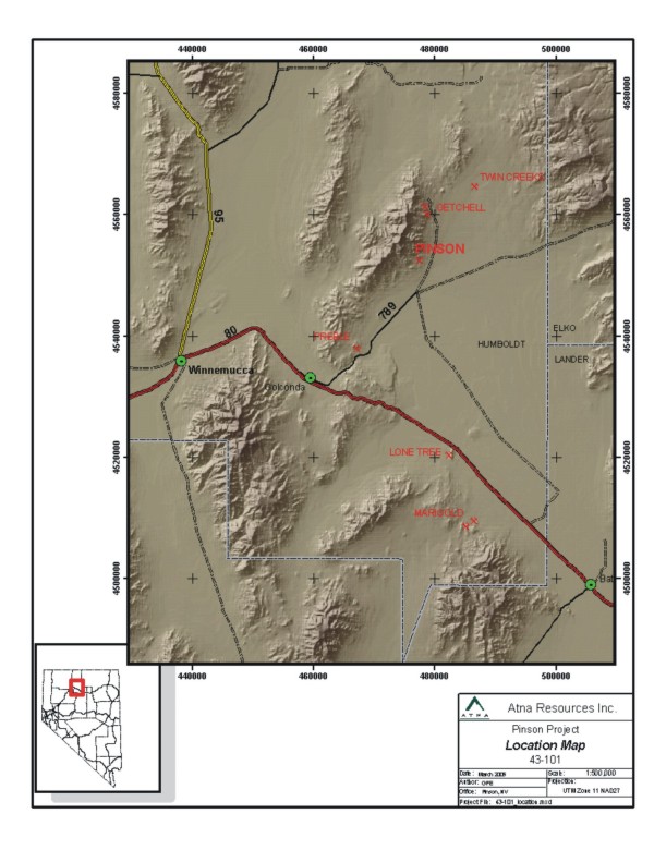
Figure
4-1. Location Map of the ▇▇▇▇▇▇ Mine Project
(Source:
Atna Resources, March 2005)
4.2 Land
Status and Agreements
The
▇▇▇▇▇▇ property is made up of a number of property parcels
that are either
wholly owned by ▇▇▇▇▇▇ Mining Company or under lease/option
by ▇▇▇▇▇▇ Mining
Company and therefore subject to the Atna-▇▇▇▇▇▇ Mining Company
(“PMC”) earn-in
agreement. The property includes 3,800 acres of patented fee
lands wholly owned
by PMC, 360 acres of leased patented fee lands, 8,496 acres
of federal
unpatented lode mining claims wholly owned by PMC, 1,362 acres
of leased federal
unpatented lode claims. A total of 553 unpatented federal lode
mining claims
(both owned and leased by PMC) are included in the property
position. Total
acreage controlled by ▇▇▇▇▇▇ Mining Company and subject to
Atna’s earn-in
agreement is 14,018 acres.
Figure
4-2, Land Status, shows the general property positions held
by PMC
and
subject to the earn-in agreement between Atna Resources and
▇▇▇▇▇▇ Mining
Company.
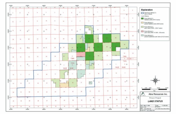
Figure
4-2. Generalized Land Status Map
(Source:
Atna Resources, Inc., March 2005)
A
text
summary of the land position is shown in Appendix
4-1, ▇▇▇▇▇▇ 2005 Land Budget Projection, and
in
extended table form in Appendix
4-2, Exhibit A Part I, Unpatented Mining Claims and Appendix
4-3, Exhibit A Part
II, Fee Lands.
The
Company has received a title opinion on the core area of four
square miles of
the ▇▇▇▇▇▇ property, within which all currently identified
mineral resources and
currently perceived exploration potential of the property exists,
rendered by
▇▇▇▇▇▇▇ ▇▇▇▇▇▇▇▇ of ▇▇▇▇▇▇ & ▇▇▇▇▇▇▇▇, Reno, Nevada (See Figure 4-3 for Area
of Detailed Title Opinion).
4.2.1 ▇▇▇▇▇▇
Mining Company Agreement
▇▇▇▇
and
PMC executed an Exploration Agreement with Option for Mining
Venture on August
12th, 2004. The agreement allows Atna, through exploration
and property
maintenance expenditures, to earn up to a one hundred percent
(100%) interest in
the project over a four (4) year period. Under the terms of
the agreement, Atna
is obligated to spend US$1.5 million in the first year of the
agreement on
exploration and property maintenance on the ▇▇▇▇▇▇ Property
(this phase of the
earn-in was completed by Atna prior to December 31st, 2004).
Additionally, Atna
must spend an additional US$10.5 million during the next three
years of the
agreement (US$12.0 million total) and deliver to ▇▇▇▇▇▇ Mining
Company a
pre-feasibility study on the mineral resources evaluated on
the property. Once
the US$12.0 million in exploration expenditures are completed
and the
pre-feasibility study is provided to PMC, Atna will vest in
a 70% joint venture
interest in the property. Figures 4-2, Generalized Land Status
and Figure 4-3,
Detailed Land Status and Agreement Map, display the Area of
Interest for the
Exploration Agreement with Option for Mining Venture and the
land holdings
within the Area of Interest.
After
▇▇▇▇’s completion of the required earn-in expenditures and delivery
of the
pre-feasibility study to PMC, the agreement allows PMC several
options going
forward. PMC may elect to:
1)
Participate as a 30% joint venture partner in the continued
development of the
project (Atna remains operator);
2)
Back-in to a 70% joint venture interest in the project via
the expenditure of
US$30.0 million over a 36 month period (PMC would be operator
during the back-in
period); or
3)
Elect
to offer to sell its 30% interest in the project to Atna for
US$15.0 million.
PMC must make its election within 60 days of Atna’s completion of its earn-in
requirements. If Barrick elects to sell its interest to Atna,
Atna may either
elect to purchase the interest or to not purchase the interest.
If Atna elects
to purchase PMC’s remaining 30% interest, Atna has a nine-month period to
arrange the financing to close the purchase.
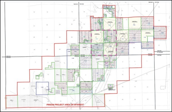
Figure
4-3, Detailed Land Status and Agreement Map
(Source:
Atna Resources, Inc. & ▇▇▇▇▇▇ Mining Company, August 2004 - March
2005)
4.2.2 Underlying
Agreements - Unpatented Federal Mining Claims
Several
lease agreements are in place to control portions of the properties
comprising
the ▇▇▇▇▇▇ Project land holdings. Because of the complex ownership
and royalty
interests in the project area, all readers should consult Figure
4-3, Detailed
Land Status while reading the summary text of the underlying
agreements in
Sections 4.2.2, 4.2.3, and 4.2.4. Additionally, Table 4-1,
Land and Royalty
Summary, follows Section 4.2.4 and summarizes the complex land
status and
royalty agreements related to the property subject to the Atna-▇▇▇▇▇▇
Mining
Company agreement.
4.2.2.1 BEE
DEE group
Newmont
Capital Limited (50%) and ▇. ▇. ▇▇▇▇▇▇ Trust (50%) are the
underlying owners of
the BEE DEE group of 58 unpatented federal mining claims located
in Sections 4,
5 and 6 of Township 37 North, Range 42 East and Sections 31,
32, and 33 of
Township 38 North, Range 42 East. The agreement provides for
annual minimum
advanced royalty payments, paid in monthly installments, to
the owners totaling
US$73,608 and the maintenance of the unpatented claims. Maintenance
fees to the
Bureau of Land Management and Humboldt County are current and
the next fees,
US$7,476.00, will be due in August and October 2005. The agreement
expires March
8, 2010 unless extended by either PMC or Atna by written notice
for an
additional 10-year term.
The
agreement calls for a royalty of 4% Net Smelter Return until
royalties totaling
US$500,000 are paid to the owners. Thereafter, the royalty
is 2% Net Smelter
Return. All advanced production royalty payments are credited
against actual
production payments due.
4.2.2.2 ▇.
▇. ▇▇▇▇▇ Unpatented Claims
▇▇.
▇▇▇▇▇
is the underlying owner of 23 unpatented lode claims held by
PMC under the terms
and conditions of a Mining Lease agreement which expires on
February 14, 2011
unless renewed by PMC by written notice. Of the 23 claims covered
under the
lease, 5 claims are within the ▇▇▇▇▇▇ Project area of interest
and are part of
Atna’s property (Section 20, Township 38 North, Range 42 East).
The terms of the
agreement call for an annual advanced royalty payment of US$506
(pro-rata share
of claims within the ▇▇▇▇▇▇ Project area of interest) per year
and PMC is
required to maintain the unpatented claims in good standing.
Maintenance fees to
the BLM and Humboldt County are currently US$3,071 per year,
with the next fees
due in August and October of 2005.
The
lease
carries a mineral production royalty of 5% Net Smelter Return
(conventional
milling) or a 4% Net Smelter Return (heap ▇▇▇▇▇) royalty. All
advanced
production royalty payments are credited against actual production
payments
due.
4.2.2.3 VEK/▇▇▇▇▇▇
Unpatented Claims
VEK
Associates and ▇▇▇▇▇▇ Resources Corporation are owners of 56
unpatented lode
claims under lease by PMC and subject to the Atna-PMC agreement.
Term of the
lease continues through June 14, 2008 unless extended by written
notice by PMC.
The lode claims are located in Sections 4, 8, and 16, Township
37 North, Range
42 East. PMC’s lease agreement with VEK/▇▇▇▇▇▇ includes provisions for a
minimum
annual advanced royalty payment of US$25,000 (currently payment
is US$31,000),
indexed to the consumer price index. Maintenance of the unpatented
mining claims
is the responsibility of PMC and will be US$7,076.00, due in
August and
September, 2005.
The
agreement calls for a production royalty of 4% Net Smelter
Return on all mineral
production from the subject property. All advanced production
royalty payments
are credited against actual production payments due.
4.2.3 Underlying
Agreements - Patented Fee Lands
Three
lease agreements are in place controlling three separate patented
fee land
parcels within the Atna-PMC area of mutual interest at the
▇▇▇▇▇▇
Property.
4.2.3.1 ▇▇▇▇▇▇▇▇▇▇,
et al Lease
A
58.3333% interest in a 120 acre parcel in the southwest quarter
of Section 28,
Township 38 North, Range 42 East, is subject to a Mining Lease
agreement between
PMC and ▇. ▇▇▇▇▇▇▇▇▇▇ (50% interest) and ▇. ▇▇▇▇▇▇ (8.3333%
interest). The other
41.6667% interest in this patented land parcel is owned directly
by PMC (subject
to a 2% retained Net Smelter Return Royalty by the sellers
on their pro-rata
undivided interest). The ▇▇▇▇▇▇▇▇▇▇ lease provides for annual
advanced royalty
payments totaling US$17,172 per year (payable monthly on a
pro-rata ownership
basis).
The
agreement also provides for a Net Smelter Return Royalty of
3% until
US$1,500,000 in royalty payments have been made upon which
the production
royalty rate decreases to 2%. All advanced royalty payments
are credited against
any future actual production royalties.
4.2.3.2 ▇.
▇▇▇▇▇ Lease
The
▇▇▇▇▇
lease covers a 40 acre patented fee land parcel described as
the southeast
quarter of the northeast quarter of Section 13, Township 37
North, Range 42
East. The lease calls for an advanced minimum royalty payment
of US$1,000
annually from January 1, 2006 through January 1, 2010 and US$1,500
annually from
January 1, 2011 through January 1, 2015. Unless extended by
mutual agreement,
the lease will terminate on December 31, 2015.
Included
in the agreement is a retained production royalty of 5% Net
Smelter Return for
milled ores and 4% of Net Smelter Return for heap leached ores
or other lower
recovery processing, payable to ▇▇▇▇▇. No mineral production
has occurred on the
property to date.
4.2.3.3 ▇▇▇▇▇▇
Lease
PMC
leases 1,160 acres of land from ▇. ▇▇▇▇▇▇ in the region and
320 acres of the
lease are a part of the ▇▇▇▇▇▇ Project lands. The lease cost
per year to the
Pinson Project is US$3,040, and is recoupable from actual production
royalty
payments for those payments made after January 1, 2002 ( payments
are paid
annually). The lands subject to this agreement are more specifically
described
as the south one-half of Section 13, Township 37 North, Range
42 East. The
agreement expires on December 31, 2013 unless extended by written
notice to
▇▇▇▇▇▇.
The
lease
calls for a 5% Net Smelter Return production royalty on all
minerals produced
from the property. To date, no mineral production has been
made from the ▇▇▇▇▇▇
portion of the property.
4.2.4 Underlying
Agreements - Other Agreements
Several
other agreements affect the lands subject included in the Atna-PMC
agreement
including the ▇▇▇▇▇▇▇▇▇▇ Seven Dot Range Management agreement.
4.2.4.1 ▇▇▇▇▇▇▇▇▇▇
- Seven Dot Agreement
This
agreement provides annually US$10,000 to be deposited and drawn
upon for range
improvements by the ▇▇▇▇▇▇▇▇▇▇’▇ Seven Dot cattle operation. Only 50% of this
cost is borne by the ▇▇▇▇▇▇ Project with the remainder paid
by PMC for the
remaining acreage which includes lands near its ▇▇▇▇▇▇ project
to the south of
the ▇▇▇▇▇▇ property. This fund was set up to allow PMC to assist
and mitigate
effects of its operations on the ▇▇▇▇▇▇▇▇▇▇ cattle business
and avoid the
continual requests for assistance from its neighbors, the Christisons,
to
provide backhoes, grader, or bulldozer work to benefit their
cattle grazing
business.
4.2.4.2 ▇▇▇▇▇▇▇
(Glamis Gold) Acquisition
▇▇▇▇▇▇▇
Gold and Homestake Mining (co-owners of ▇▇▇▇▇▇ Mining Company
at the time)
purchased ▇▇▇▇▇▇▇’s (now Glamis Gold) interest in ▇▇▇▇▇▇ Mining Company on
November 30, 1996 and Homestake became operator of the ▇▇▇▇▇▇
Mine (which was in
production at the time). Subsequent to this purchase, ▇▇▇▇▇▇▇
Gold purchased
Homestake and therefore PMC is not a wholly owned subsidiary
of ▇▇▇▇▇▇▇
Gold.
This
purchase transaction included an overriding royalty interest
in the lands
controlled by ▇▇▇▇▇▇ Mining Company at the time of the transaction.
This
overriding royalty varies dependent upon the type of land (patented
fee versus
unpatented claims) and any underlying royalties existing on
both owned and
leased parcels at the time of the transaction. For fee lands
owned by ▇▇▇▇▇▇
Mining Company, Rayrock would be paid a 2.5% Net Smelter Return
Royalty on lands
not subject to an underlying royalty and 0.5% on those parcels
subject to a
royalty which would increase to a 1% Net Smelter Return royalty
if the average
gross value per ton of ore produced was greater than US$175/ton.
On
fee
lands leased by ▇▇▇▇▇▇ Mining Company and subject to royalties
payable to a
third-party, the Rayrock royalty would vary from a minimum
of 0.5% Net Smelter
Return to a maximum of 5% Net Smelter Return as a result of
the underlying
royalty. The royalty percentage to Rayrock will be determined
as the difference
between a total royalty load of 6% less the underlying royalty;
however the
royalty will not exceed 5% or be reduced to less than 0.5%
Net Smelter Return.
For example, if the underlying royalty is 4%, then the Rayrock
overriding
royalty would be 6% less 4%, or a 2% royalty payable to Rayrock.
If the
underlying royalty is 0.5%, the Rayrock royalty would be 6%
less 0.5% = 5.5%,
which is greater than 5%, which would then be reduced to 5%.
If the underlying
royalty is 6% or greater, the Rayrock royalty interest would
be limited to 0.5%
of the Net Smelter Return.
If
the
lands were controlled by unpatented lode mining claims and
not subject to
underlying third-party agreements with retained royalties,
the retained
production royalty would be 2.5% Net Smelter Return. If the
unpatented mining
claims have underlying retained royalties, then the Net Smelter
Return royalty
would be determined as is the royalty described above under
the patented lands
leased by PMC and subject to an underlying royalty, again with
a maximum of 5%
Net Smelter Return and a minimum of 0.5% Net Smelter Return
royalties dependent
upon the underlying royalty load.
Additionally,
there is a production royalty “holiday” from production from existing pits and
extensions of mineralization within the pits applicable to
this agreement. The
initial “holiday” was limited to 200,000 ounces of gold production and there
remains approximately 80,000 “holiday” gold ounces remaining prior to the
project incurring any liability on this overriding royalty.
4.2.4.3 Cordilleran
Overriding Royalty
Cordilleran
Exploration, the original developers of the ▇▇▇▇▇▇ Project,
hold an overriding
royalty position on several parcels including the patented
lands of Sections 21
and 29, Township 38 North, Range 42 East. Cordilleran has a
3% Net Smelter
Return production royalty on Section 21 and a 5% Net Smelter
Return royalty on
Section 29. Cordilleran also holds an overriding royalty on
the Cord and Pacific
unpatented lode mining claims of 5% of Net Smelter Return.
Both these parcels
are in turn subject to the Rayrock overriding royalty. The
Cordilleran royalty
also covers the Tip Top claims in the south half of Section
30, Township 38
North, Range 42 East, and the Pacific claims making up the
majority of the west
half of the northwest quarter and the northwest quarter of
the southwest quarter
of Section 28, Township 38 North, Range 42 East.
4.2.4.4 ▇▇▇▇▇▇▇▇
Gold/Newmont Capital Overriding Royalty
PMC
purchased three and three-quarter square miles of fee lands
from the ▇▇▇▇▇▇▇▇
Mine. ▇▇▇▇▇▇▇▇ retained a 5% Net Smelter Return Royalty on
these parcels
(Sections 23, 27, 33, and the west one half and northeast quarter
of Section 25,
Township 38 North, Range 42 East. Additionally, Newmont Capital
controls (via
its acquisition of Euro Nevada Corporation) an additional 2%
Net Smelter Return
royalty on these parcels.
4.2.4.5 Echo
Bay Lands
PMC
purchased unpatented lode mining claims owned by Echo Bay Mines
(now Kinross) in
1998. Echo Bay retained a 2.5% Net Smelter Return Royalty on
the claims sold to
PMC. Additionally, these lands were subject to a finder’s fee agreement between
Echo Bay and ▇▇▇▇ ▇▇▇ where Mr. ▇▇▇ is due US$5,000 per year
or a 1% Net Smelter
Return Royalty for bringing the claims to Echo Bay. Mr. ▇▇▇’s royalty interest
is subject to a maximum payment of US$135,000 in royalties
or advanced
royalties. Mr. ▇▇▇ is due a minimum annual payment of US$5,000.
Lands subject to
this royalty override are the claims located in the Sections
24, 26, 35 and the
north half of Section 36, Township 38 North and Section 30,
Township 38 North,
Range 43 East.
4.3 Royalty
Summary
The
▇▇▇▇▇▇ property package is made up of 38 property parcels and
nearly all are
burdened by one or more retained mineral production royalties.
Each parcel’s
royalty agreement (or agreements) is structured slightly different
than others
and therefore the royalty for any given parcel is likely to
be slightly
different than an adjacent parcel. The mineral resource, the
primary focus of
this technical report, occurs entirely within Sections 28,
29, 32, and 33;
Township 38 North; Range 42 East. Due to the relatively high-level
of
uncertainty for resource-level tonnage and grade calculations,
particularly when
the majority of the resource is categorized as “Inferred”, Atna has not yet
broken down the resource into individual property parcels.
Additionally, many of
the retained production royalty agreements include advanced
royalty payments
(see above sections) that are recoupable from actual production
royalty
payments, therefore initially the actual royalties paid upon
commencement of
production from any given parcel may be significantly less
than the stated
royalty rate defined in the table below. Ultimately, should
a minable reserve be
established, Atna will determine exactly what resource blocks
are located on
which parcels such that an accurate mine plan, royalty payment
burden, and cash
flow model for the project may be established as part of a
full feasibility
study on the project’s mineral resources and or reserves (if reserves are
established in the future).
Table
4-1
is a summary of the individual royalty burden on all parcels
subject to the
Atna-PMC earn-in agreement:
Table
4-1: Royalty Summary
|
Parcel
Location
|
Property
Description
|
Acreage
|
Royalty
Description
|
|
Township
38 North, Range 41 East
|
|||
|
Section
36
|
18-lode
claims-PMC
|
360
|
5.0%
NSR; and $0.50 per ton of ore produced.
|
|
Township
38 North, Range 42 East
|
|||
|
Section
16
|
12-lode
claims
|
264
|
5.5%
NSR
|
|
3-lode
claims
|
56
|
5.0%
NSR
|
|
|
Section
20
|
28-lode
claims
|
460
|
No
Royalty Burden
|
|
5-lode
claims
|
102
|
4
-5% NSR on precious metals, 2.5% NSR on base metals,
& $1.00 to
$1.50/ton for barite or barium based on specific
gravity of
ore.
|
|
|
4-lode
claims
|
78
|
5.5%
NSR
|
|
|
Section
21
|
640
acres of private land
|
640
|
5.5%
NSR
|
|
Section
22
|
18-lode
claims
|
360
|
5.0%
NSR
|
|
Section
23
|
640
acres of private land
|
640
|
7.5%
NSR.
|
|
Section
24
|
36-lode
claims
|
640
|
2.5%
NSR
1.0%
NSR capped at $135,000
|
|
Section
25
|
480
acres of private land
|
480
|
7.5%
NSR
|
|
Section
26
|
36-lode
claims
|
640
|
2.5%
NSR)
1.0%
NSR capped at $135,000
|
|
Section
27
|
640
acres of private land
|
640
|
7.5%
NSR.
|
|
Section
28
(see
footnote 1)
|
23-lode
claims
|
400
|
5.0%
NSR
|
|
7-lode
claims
|
120
|
5.5%
NSR
|
|
|
120
acres, private land
|
50
(net)
|
2.0%
NSR
|
|
|
70
(net)
|
5.0%
NSR
|
||
|
Section
29
(see
footnote 1)
|
640
acres of private land
|
640
|
5.5%
NSR
|
|
Section
30
|
32-lode
claims- PMC
|
545
|
No
Royalty burden
|
|
5-lode
claims-PMC
|
95
|
5.0%
NSR
|
|
|
Section
32
(see
footnote 1)
|
18-lode
claims
|
370
|
2.0%
NSR
|
|
20-lode
claims
|
270
|
5.0%
NSR
|
|
|
Section
33
(see
footnote 1)
|
640
acres of private land
|
640
|
7.5%
NSR
|
|
Section
34
|
36-lode
claims
|
640
|
2.5%
NSR
1.0%
NSR capped at $135,000
|
|
Section
36
|
18-lode
claims
|
320
|
2.5%
NSR
1.0%
NSR-capped at $135,000
|
|
Township
38 North, Range 43 East
|
|||
|
Section
30
|
36-lode
claims
|
640
|
2.5%
NSR
1.0%
NSR-capped at $135,000
|
|
Township
37 North, Range 41 East
|
|||
|
Section
12
|
25-lode
claims
|
450
|
5.0%
NSR
$0.50
per ton of ore produced
|
|
Section
13
|
40-acre
fee land
|
40
|
5.0%
- 5.5% NSR
|
|
320-acre
fee land
|
320
|
5.0%
- 5.5% NSR
|
|
|
Section
14
|
24-lode
claims
|
438
|
5.0%
NSR and
$0.50
per ton of ore produced
|
|
Township
37 North, Range 42 East
|
|||
|
Section
4
|
10-lode
claims
|
200
|
No
Royalty burden
|
|
20-lode
claims
|
320
|
5.0%
NSR
|
|
|
8-lode
claims
|
120
|
5.0%
NSR
|
|
|
Section
6
|
36-lode
claims
|
640
|
5.0%
NSR
|
|
Section
8
|
30-lode
claims
|
520
|
5.0%
NSR
|
|
6-lode
claims
|
120
|
No
Royalty
|
|
|
Section
16
|
3-lode
claims
|
50
|
5.0%
NSR
|
|
Section
18
|
18-lode
claims
|
360
|
5.0%
NSR and
$0.50
per ton of ore produced
|
|
18-lode
claims
|
280
|
2.5%
NSR
1.0%
NSR-capped at $135,000
|
|
|
Total
Acreage
|
14,018
|
||
Table
Footnotes
| 1) |
The
resource announced in February 2005 by Atna Resources,
Ltd. for the ▇▇▇▇▇▇
project and supported by the ▇▇▇▇▇▇ Gold Property
Technical Report (NI
43-101, Technical Report filed in March 2005 with
Sedar) is located with
in four (4) square miles highlighted in the land/royalty
table above
(Sections 28, 29, 32, and 33 of Township 38 North,
Range 42 East). Due to
the relatively high-level of uncertainty for resource-level
tonnage and
grade calculations, particularly when the majority
of the resource is
categorized as “Inferred”, Atna has not yet broken down the resource into
individual property parcels. Ultimately, should a
minable reserve be
established, Atna will determine exactly what resource
blocks are located
on which parcels such that an accurate mine plan,
royalty payment burden,
and cash flow model for the project may be established
as part of a full
feasibility study on the project’s mineral resources and or reserves (if
reserves are established in the
future).
|
5.0 Accessibility,
Climate, Local Resources, Infrastructure and Physiography
5.1 Accessibility
Road
access to the ▇▇▇▇▇▇ Mine is by traveling east from Winnemucca
on Interstate 80
for 15 miles (24 km), turning north at the Golconda exit, proceeding
through
Golconda to Nevada State Highway 789 and continuing to the
end of the paved road
(16 miles). At that point the road forks and is unpaved. The
right fork leads to
the ▇▇▇ ▇▇▇▇▇▇ Mine and the townsite of Midas. The left fork
leads to ▇▇▇▇▇▇
Mine (4 miles), ▇▇▇▇▇▇▇▇ and Turquoise Ridge Mines (11 miles)
and terminates at
Twin Creeks Mine (15 miles).
5.2 Climate
There
are
11 climatologic stations within a radius of approximately 80
miles from the
▇▇▇▇▇▇ Mine project area. These stations include: Battle Mountain,
▇▇▇▇▇▇
Newmont Mine, Golconda, Gold Banks Mine, ▇▇▇▇▇, ▇▇▇▇▇▇▇ Creek,
Paradise Valley
Ranch, Paris Ranch, Rye Patch Dam, Sleeper Mine and Winnemucca,
the closest
weather station to ▇▇▇▇▇▇ Mine. Climatological records from
these stations range
in duration from 2 to 65 years. Precipitation data from the
▇▇▇▇▇▇ Mine are also
available from 1980 up to the present. Based on the available
data, the average
monthly and annual precipitation, temperature, and evaporation
for the ▇▇▇▇▇▇
Mine project area were developed. (Water Management Consultants,
1998).
Precipitation,
although low, occurs steadily from October through June, and
falls significantly
in July through September. In a typical year, there are 27
days with measurable
precipitation, amounting to 16” of snow and 8” of rain.
Based
on
30-year averages, these are the expected seasonal variations
in
temperatures:
Table
5-1: Seasonal Temperature Variations
|
Month
|
Extreme
Low
|
Average
Low
|
Average
High
|
Extreme
High
|
|
January
|
-
1
F (- 18 C)
|
17
F (- 8 C)
|
41
F ( 5 C)
|
57
F (14 C)
|
|
April
|
16
F (- 9 C)
|
31
F (- 1 C)
|
62
F (17 C)
|
80
F (27 C)
|
|
July
|
38
F (3 C)
|
53
F (12 C)
|
91
F (33 C)
|
102
F (39 C)
|
|
October
|
15
F (- 9 C)
|
31
F (- 1 C)
|
67
F (20 C)
|
84
F (29 C)
|
5.3 Local
Resources and Infrastructure
5.3.1 Background
Nevada
is
a mining state and well accustomed to mining. Humboldt County
itself is entirely
rural, with one population center, Winnemucca, the county seat,
located in the
southeastern part of the county. Winnemucca describes itself
as a "high desert
city full of classic charm," which has been continuously occupied
since about
1830 when it became a base camp for trappers, and later as
a way-station for
pioneers migrating to the California goldfields after 1849
(Winnemucca, NV web
site, 2005). Historically, Winnemucca was a local ranching
community which
branched out into support for large-scale mining following
the discovery of
significant gold deposits in the 1980s. Today, Winnemucca continues
in that
role, and has evolved as well into a jumping-off point for
local outdoor
recreation, as it is surrounded by vast tracts of Federally-administered
public
lands.
5.3.2 Physical
Infrastructure
The
major
highways are paved or well maintained. Interstate 80 traverses
the northern
third of Nevada, from Wendover, Utah to Verdi, California.
State Highway 789,
leading from Golconda northeast towards ▇▇▇▇▇▇, is paved to
within 4 miles of
▇▇▇▇▇▇. The unpaved portion, which begins as a "Y" junction
at the end of
pavement, is considered a private road under the control of
Newmont Mining
Corporation. That road is well maintained and serves as the
main access roads to
both Newmont’s Twin Creeks Mine complex and Placer Dome’s ▇▇▇▇▇▇▇▇ and Turquoise
Ridge mines.
Winnemucca
is served by a general aviation airport and daily passenger
rail service. Bus
service was terminated several years ago.
Landline
dialup telephone service for the Internet is slow from the
minesite (28.8 kb via
modem, or less), but high-speed broadband is available through
satellite.
Cellular phone service is available, but contingent on the
strength of receiving
antennas, topography and lines of sight.
5.4 Adjacent
Operations
Two
active mine sites exist a few miles further north of ▇▇▇▇▇▇:
the
▇▇▇▇▇▇▇▇/Turquoise Ridge complex at 5 miles, and the Twin Creeks
complex at 10
miles. Both sites create much passenger vehicle, shuttle bus
and freight-truck
traffic. In particular, Newmont ships refractory gold ores
from other Northern
Nevada properties to Twin Creeks for processing, and all ▇▇▇▇▇▇▇▇/Turquoise
Ridge ores are processed at the Twin Creeks facilities.
5.5 Physiography,
Flora, and Fauna
5.5.1 Physiography
The
▇▇▇▇▇▇ Mine is situated in the Great Basin physiographic province
and the Basin
and Range tectonic province. North-south mountain ranges and
parallel
intermontane basins characterize the area. The entire region
is a closed
drainage system with all the permanent streams flowing to interior
"sinks" such
as the ▇▇▇▇▇▇ and Humboldt sinks, or interior lakes such as
Pyramid and ▇▇▇▇▇▇.
Elevations in the area range from about 4,000 feet above mean
sea level in the
basinal areas, to over 9,000 feet in the surrounding ranges.
The terrain is
generally moderate.
5.5.2 Flora
The
▇▇▇▇▇▇ Mine area is located in a sagebrush vegetation community,
with mixed
sagebrush-grass zones occurring at higher elevations or in
broad valleys.
Sagebrush and shrub species observed in the compilation of
earlier environmental
assessments (EAs) for ▇▇▇▇▇▇ include two varieties of sagebrush
(big and low);
three of rabbitbrush (rubber, green and low); bitterbrush;
little leaf
horsebrush; and desert peach. Grasses recognized include ▇▇▇▇▇▇▇▇
bluegrass,
cheatgrass, Basin wild rye, wheatgrass, needlegrass, pepperweed,
Russian
thistle, halogeton, phlox, lupine, balsamroot and Indian paintbrush
(BLM,
2001).
5.5.3 Fauna
The
area
supports a large number of small mammals, in particular ▇▇▇▇▇▇▇’▇ cottontail
rabbit and the black-tailed jackrabbit. These are by far the
most commonly
observed animals. Other small mammals known in the area include
the deer mouse,
western harvest mouse, Great Basin pocket mouse, long-tailed
vole,
chisel-toothed kangaroo rat, least chipmunk, and ▇▇▇▇▇▇▇▇’▇ ground squirrel
(BLM, 2001). Mule deer and antelope also inhabit the foothills.
Predator mammals
identified as occasional visitors would include mountain lion,
bobcat, coyote
and badger. Scorpions and bull snakes have been seen on the
property (La Peire,
personal communication, 2005)
The
vegetation is sufficiently dense to provide habitat suitable
for small ground-
and shrub-nesting birds, such as horned larks, sparrows, sage
thrashers,
nighthawks, barn swallows, meadowlarks, magpies and flycatchers.
Game birds
include mourning doves, California and mountain quail, sage
grouse, Hungarian
▇▇▇▇▇▇▇▇▇ and chukars. Raptor nests are not in evidence, but
it is likely that
golden eagles, western burrowing owl, ferruginous hawks and
prairie falcons are
the principal avian predators (BLM, 2001). A pair of ravens
has occupied the pit
areas throughout Atna’s exploration program.
6.0 History
6.1 Summary
Mineral
exploration and discovery developed fitfully in this valley,
beginning with the
post-Civil War discovery of gold and silver in the ▇▇▇▇▇▇ Range,
resulting in
the organization of the Fremont Mining District in 1874 and
its reorganization
into the Potosi Mining District in 1878. The district as now
defined extends
from ▇▇▇▇▇ Creek Valley on the east to the south end of the
▇▇▇▇▇▇ on the west,
approximately diagonally southwest from T. 39 N., R. 42 W.
to T. 37 N., R. 40 W.
(▇▇▇▇▇▇▇, 1998, p. 57).
6.2 Initial
Discovery
Within
the valley, mineral production was not significant until the
discovery of the
▇▇▇▇▇▇▇▇ Mine in 1934. That discovery initiated a period of
gold production
there which continued intermittently until 1967. During this
period local
ranchers, ▇▇▇▇▇▇▇ ▇▇▇▇ and ▇▇▇▇▇▇ ▇▇▇▇▇▇, prospected and discovered
small
siliceous outcrops resembling ▇▇▇▇▇▇▇▇ ore, and leased them
to the ▇▇▇▇▇▇▇▇ Mine
owners, resulting in mining of approximately 100,000 tons in
1949-1950 from an
initial pit exposing ore grading 0.14 ounce per ton (opt) gold
(4.8 g/t)
(▇▇▇▇▇▇▇▇▇▇, 1983; ▇▇▇▇▇▇▇▇▇ et al., 2000).
6.3 Pre-1970
Development
Exploration
efforts between 1950 and 1970 were limited to two programs:
| · |
A
1963 drilling campaign by Nevada Goldfields Corporation
to prove up a
resource of 47,000 tons @ 0.17 opt (5.8
g/t)
|
| · |
A
1968 JV between Getty Oil and Homestake Mining to
explore the ▇▇▇▇▇▇
claims and complete 2 core holes
|
6.4 Cordex
Syndicate Exploration and Development
The
property remained functionally dormant until 1970, when an
exploration group
known as the Cordex I Syndicate (▇▇▇▇ ▇▇▇▇▇▇▇▇▇, ▇▇▇▇▇ ▇▇▇▇▇
and Rayrock
Resources) leased the property on the strength of its similarity
to ▇▇▇▇▇▇▇▇ and
structural position along the range-front fault zone bordering
the Osgoods.
Following a surface mapping and sampling program, 17 rotary
holes were completed
in and around the initial ▇▇▇▇▇▇ pit in 1971 and confirmed
only low-grade gold
values. An 18th step-out hole discovered a 90' (27.4 m) intercept
of 0.17 (5.8
g/t), indicative of a subcropping extension to known mineralization
northeast of
the original pit, resulting in the definition of what would
become the "A" zone
at the ▇▇▇▇▇▇ property - a 60 foot x 1,000 foot shear zone
estimated to contain
1.5 M tons of 0.18 opt Au.
Continued
exploration southwest of the original pit defined the "B" zone,
estimated at 1.7
M tons at 0.15 opt Au. No production was attempted at the time
because of low
gold prices ($65 per oz) (▇▇▇▇▇▇▇▇▇▇, 1983; ▇▇▇▇▇▇▇▇▇ et al.,
2000).
The
gradual rise of gold prices to > $250 per oz. in the late 1970s allowed the
Cordex I Syndicate - which then consisted of several minority
partners - to
reorganize into a partnership known as ▇▇▇▇▇▇ Mining Company,
with Rayrock Mines
as the operator, and begin production. Homestake Mining Company
and ▇▇▇▇▇▇▇ Gold
became partners in ▇▇▇▇▇▇ Mining through their purchase of
some of the minority
interests (▇▇▇▇▇▇▇▇▇ et al., 2000).
6.5 ▇▇▇▇▇▇
Mining Company Exploration and Development
▇▇▇▇▇▇
Mining began development of the A Pit in 1980, and produced
gold from it the
next year. Production from the B Pit followed in 1982. Step-out
drilling in
1982-1983 to the northeast of the A zone intersected 2 more
discrete zones: the
C zone extending ENE from the A zone, and the CX zone extending
NE from the C
zone. C zone production replaced the final B zone production
in 1988, and CX
production was delayed until 1990, owing to the slightly greater
stripping
requirement to reach ore.
Step-out
drilling NE of the CX zone in 1984 located an apparently independent
fault
system (striking NNW, dipping steeply E) that became the core
of the MAG
Deposit, which went into production in 1987. In 1993, step-out
drilling NW of
the CX zone once again established more ore in proximity, a
CX West zone
subparallel to, and closer to, the ▇▇▇▇▇▇ Mountain front. ▇▇▇▇▇▇
Mining Company
produced from the CX, CX West and MAG pits as long as possible
in the mid to
late 1990s, until a combination of falling gold prices and
erratic mill feed
forced closure of its oxide mill in early 1998. Continued attempts
to expand
production of oxide ore failed, and all active mining ceased
on January 28, 1999
(▇▇▇▇▇▇▇▇▇ et al., 2000).
6.6 Homestake-Barrick
Exploration
Homestake
and Barrick conducted a JV exploration program from 1996 to
2000 expending some
$12 million on the project. The JV then determined it would
not expend any
further funds on exploration. Subsequent to that decision,
Barrick acquired
Homestake Mining Company and drilled an additional three exploration
drill holes
in 2003.
6.7 ▇▇▇▇▇▇
Project Production Summary
Historically,
the district was credited with Au production in excess of 1
M oz, but less than
100,000 oz. ▇▇ (▇▇▇▇▇▇▇, 1998, p. 108 & 120). Independently, Barrick
compiled a similar record of production and credits the ▇▇▇▇▇▇
mine property
with production of 986,000 ounces of gold (Appendix
6-1, Discovery & Production History).
6.8 Atna
Resources Exploration
Atna
Resources began project planning during July of 2004 and began
drilling at the
▇▇▇▇▇▇ property in August 2004 after the execution of the earn-in
agreement with
▇▇▇▇▇▇ Mining Company on August 12th.
7.0 Geological
Setting
7.1 Regional
Setting
For
the
last half-century, sediment-hosted, ▇▇▇▇▇▇-type gold systems
have accounted for
most economic gold discoveries in Nevada. Mineralization in
these environments
lies mainly in four geographic belts of mostly Paleozoic carbonate
rocks. These
belts are located in north-central Nevada, and the three most
productive pass
through the townsites of Carlin (“▇▇▇▇▇▇ Trend”), Battle Mountain (“Battle
Mountain-Eureka Trend”) and Golconda (“▇▇▇▇▇▇▇▇ Trend”). The fourth belt, the
“Independence Trend”, is located north of the town of Elko and is the location
of the Jerritt Canyon group of mines (Queenstake Resources)
and the Big Springs
Mine (Golden Gate Resources). Collectively, these belts hold
a geochemical
endowment of over 200 million ounces of gold. A key to understanding
this
endowment lies in understanding the structural relationships
of the
stratigraphic section.
The
Paleozoic era throughout north-central Nevada is a period in
which a craton
extended from the Mid-Continent westward to about the longitude
of present-day
Battle Mountain (▇▇▇▇▇▇▇, 1980). East of the inferred craton
margin was a gently
sloping (miogeoclinal) carbonate shelf, consisting of a variety
of quiet-water
quartzite, limestone, and intrabasinal shale (“Eastern Assemblage” rocks); and
west of the margin was a much deeper oceanic environment depositing
a sequence
of siliciclastic sediments, largely composed of deep-water
shale, chert, and
volcanic ashes and flows (“Western Assemblage” rocks).
During
the Paleozoic, sedimentary rocks were structurally deformed
by a series of
east-directed compressional tectonic events. There were at
least two such events
of primary importance: A Devonian-Mississippian event, transporting
pre-Devonian
deep-water sediments eastward ("Antler orogeny") created the
▇▇▇▇▇▇▇ Mountain
and associated thrust faults. This was followed by a Permo-Triassic
event,
transporting Mississippian to Permian age deep-water sediments
eastward ("Sonoma
orogeny") creating the Golconda and Humboldt Thrust faults.
A period of tectonic
quiescence, allowing for the deposition of local basin sands
and conglomerates
and shallow limestones of the “overlap” sequence, marked erosion and subsidence
during Mississippian to Permian times, and separated the two
compressional
events.
Both
compressional events deformed rock units into a series of folds,
and thrust the
western assemblage siliciclastic rocks over the eastern assemblage
carbonate
rocks, forming one of the principal structural traps necessary
for the formation
of ▇▇▇▇▇▇-type sediment-hosted gold deposits.
Compressional
tectonics continued until the earliest Tertiary with the emplacement
of granitic
stocks, the development of additional fold and thrust belts,
and the onset of
strike slip faulting. Much of this activity was west of the
Battle
Mountain-Eureka Trend, but extended as far east as Western
Utah and Southern
Wyoming.
Beginning
in Tertiary time, about 48 Ma, extensional tectonics became
the primary tectonic
regime in the Great Basin. This structural style formed a series
of horsts and
grabens, resulting in the present-day landscape of northerly
oriented parallel
mountain ranges and valleys (▇▇▇▇▇▇▇, 1980). Owing to the large
number of
▇▇▇▇▇▇-type deposits with ages between 35 and 48 Ma (Arehart
et al., 2003), the
onset of extension has been considered by some (Ilchik and
▇▇▇▇▇▇, 1997) to be
an important factor in the genesis of these deposit types.
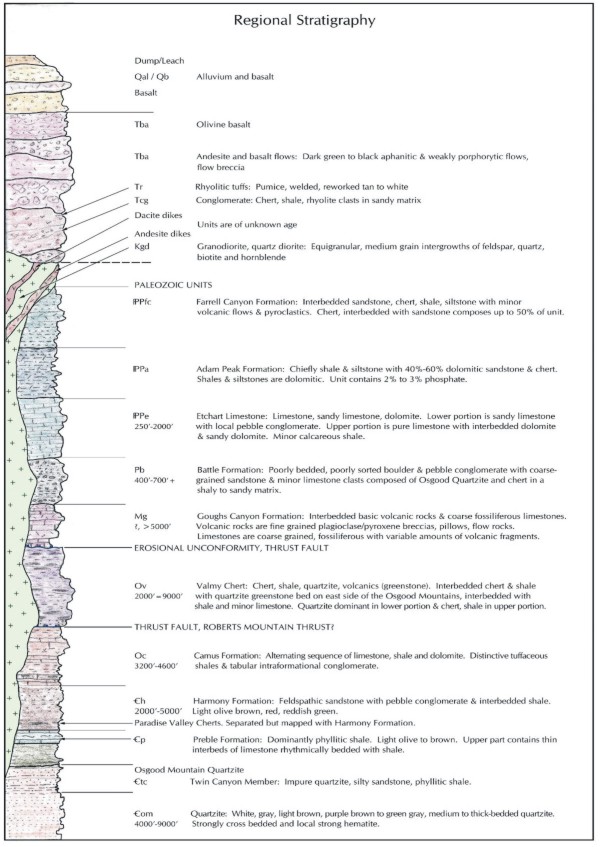
Figure
7-1. Regional Stratigraphy
(Source:
Atna Resources, March 2005)
In
a
general sense, this geologic history of north-central Nevada
is reflected
somewhat in the geology of the ▇▇▇▇▇▇ Mountains. The range,
as mapped by ▇▇▇▇
and ▇▇▇▇▇▇▇ (1964), and ▇▇▇▇▇▇▇▇ and ▇▇▇▇▇ (1974) shows a variety
of rock units
through time (Figure 7-1, Regional Stratigraphy). These initial
workers show the
oldest Cambrian-aged siliclastics (▇▇▇▇▇▇ and ▇▇▇▇▇▇ Mtn. quartzite)
to be
overlain by Ordovician carbonate rocks (Comus Formation), and
folded into a
broad, north plunging anticline. The west flank of this anticline
has been
overthrust by deep-water siliceous shale and cherts of the
Ordovician Valmy
Formation, while in the core of the range, and in scattered
localities on the
east side of the range, sands and conglomerates of the Battle
Formation and
limestones of the ▇▇▇▇▇▇▇ Formation lie unconformably on, or
are in fault
contact with, these older folded rocks (Figure 7-2, Regional
Geology).
A
second
structural event has been mapped by these early workers along
the northwest and
southern flanks of the ▇▇▇▇▇▇ Mountains. This event displaces
Mississippian
volcanics and Pennsylvanian shales, marking the Golconda and
Humboldt thrusts.
Before the onset of extension in the Tertiary, Cretaceous stocks
consisting of
diorite and granodiorite were intruded into the core of the
range, and created a
large, thermally-metamorphosed aureole with several tungsten
skarns surrounding
the stock. Capping the sequence are Tertiary volcanic rocks
consisting of older
rhyolite tuffs, Miocene basalt and andesite flows, and younger
basalt
flows.
Due
to
structural complexity and lithologic variations within the
range, more recent
workers (▇▇▇▇▇, 1991, ▇▇▇▇▇▇-▇▇▇▇▇▇▇ and ▇▇▇▇▇, 1991, and ▇▇▇▇▇▇▇▇▇
et al.,
2000) have distinguished terranes based on age, structural
history, and
lithology. Four principal terranes have been identified (Figure
7-3,
TectonoStratigraphy).
These
are:
| · |
An
▇▇▇▇▇▇ Mountain terrane, consisting of the structural
block cored by
pre-Cambrian/Cambrian ▇▇▇▇▇▇ Mountain quartzite in
the southern Osgoods,
and in the ▇▇▇▇▇▇-area, Cambrian-Lower Ordovician
▇▇▇▇▇▇ phyllites,
Ordovician Lower and Upper Comus, and an intrusive
Cretaceous granodiorite
stock. The domain of these rocks extends northward,
from ▇▇▇▇▇▇ through
▇▇▇▇▇▇ to ▇▇▇▇▇▇▇▇. Further northeast, at the Turquoise
Ridge and Twin
Creeks Mines, the Upper Comus is additionally overlain
by a local
assemblage (Twin Creeks Member) of calcareous shales
intruded by numerous
mafic ▇▇▇▇▇.
|
The
remaining three terranes are structural overlap sequences which
generally crop
out further north:
| · |
A
Leviathan allochthon terrane, presumably Ordovician,
exposed only at
Turquoise Ridge and Twin Creeks, characterized by
cherty, basaltic, and
pelagic (tuffaceous) sequences thrust over the Twin
Creeks
Member.
|
| · |
An
"Antler overlap" sequence, consisting of a regional
Battle Mountain
quartzite-rich conglomerate and overlying Pennsylvanian-Permian
▇▇▇▇▇▇▇
calcareous sandstone/fossiliferous limestone pairing,
all of which are
locally absent at ▇▇▇▇▇▇.
|
| · |
A
Golconda allochthon terrane, transporting Mississippian
Goughs Canyon and
Penn-Permian Farrel Canyon sediments, but restricted
areally to the
northern part of the ▇▇▇▇▇▇ Mountains, far from ▇▇▇▇▇▇
proper.
|
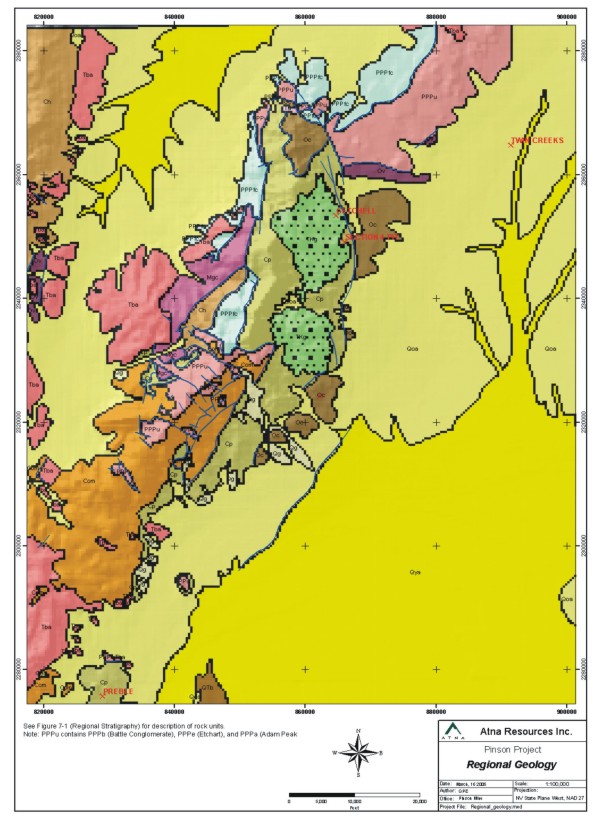
Figure
7-2 Regional Geology
(Source:
Atna Resources, March 2005)
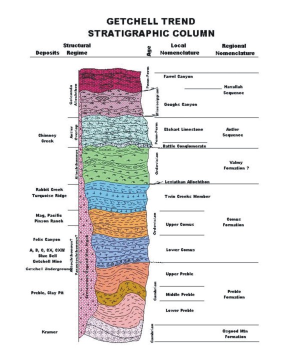
Figure
7-3. TectonoStratigraphy
(Source:
Atna Resources, March 2005)
7.2 ▇▇▇▇▇▇
Mine Setting
The
▇▇▇▇▇▇ Mine site lies on the east flank of a large stock of
Cretaceous
granodiorite which cores the southern part of the ▇▇▇▇▇▇ Mountains
(Figure 7-4,
Mine Site Geology). Sediments peripheral to the east side of
the stock dip
moderately to steeply southeast, east and northeast, depending
on their
circumferential position. The lowest stratigraphic units preserved
against the
granodiorite contact are Cambrian ▇▇▇▇▇▇ phyllitic shales,
limestone interbeds,
and variously hornfelsed sediments. These are overlain by a
thick sequence of
variegated Ordovician Comus sediments with a significant carbonate
content.
Generally, the lowest parts of the Comus are massive, micritic
limestones; the
middle portion is dominated by mixed limestone shale interbedded
sequences,
often combined with local debris flows; and the upper Comus
is characterized by
mildly to non-calcareous shales.
The
Comus
Formation is in enigmatic depositional relationship to the
underlying ▇▇▇▇▇▇
Formation. It is routinely believed to be conformable or depositional,
but in
fact at ▇▇▇▇▇▇ Mine the contact is for the most part faulted,
subparallel to the
envelope of the Range Front Fault.
The
Cretaceous granodiorite stock, emplaced at 90-92 Ma (▇▇▇▇▇
et al., 1997, cited
in ▇▇▇▇▇▇▇▇▇ et al., 2000) has created an irregular contact
metamorphic aureole
extending up to 10,000 feet (3,000 m) from its perimeter. The
effects on the
metamorphosed sedimentary section vary:
| · |
Much
of the ▇▇▇▇▇▇ section is
hornfelsed;
|
| · |
The
Upper ▇▇▇▇▇▇ in particular is converted to a maroon,
biotite-cordierite
hornfels;
|
| · |
The
Lower Comus is commonly calc-silicated (converted
to wollastonite and
idocrase);
|
| · |
The
Upper Comus may be converted to chiastolite
hornfels.
|
The
most
important structural feature of the ▇▇▇▇▇▇ Mine area is the
network of faults
that borders the escarpment marking the southern and eastern
edge of the ▇▇▇▇▇▇
granodiorite. This fault system has been variously interpreted
as a single
master fault (Range Front Fault) curving around the stock or,
more likely, a
network of shorter, straighter segments that collectively accommodate
several
thousand feet of displacement while making a 50 degree bend
around the SE corner
of the stock (▇▇▇▇▇▇ Fault on south margin; CX Fault on southeast
margin; Range
Front Fault on east margin). Sedimentary rocks in the vicinity
of this
curvilnear system generally dip steeply away from the contacts
of the
granodiorite.
The
relation of the Range Front and CX faults to ▇▇▇▇▇▇ stratigraphy
may be
characterized as follows:
| · |
The
"floor" of the complex is the ▇▇▇▇▇▇
granodiorite;
|
| · |
The
Cambrian ▇▇▇▇▇▇ may be in intrusive contact with
the
granodiorite
|
| · |
The
Range Front fault will mark the approximate location
of the contact
between the Cambrian ▇▇▇▇▇▇ and Ordovician Comus.
The contact zone will be
brittlely broken or ductilely
sheared.
|
| · |
The
CX fault zone will separate Lower Comus from Middle
Comus.
|
| · |
The
Upper Comus may be folded in a synform between the
Range Fault and CX
faults, and be involved in some Range Front mineralization,
but will not
be geometrically involved in any CX
faulting.
|
In
addition to the large-scale fault system described above, there
are numerous NW
and a few E-W structures identified in past mapping and drilling.
Generally,
these appear to be mostly older than, and truncated by, the
main system. Some of
these faults have been reactivated enough to disrupt the continuity
of the main
▇▇▇▇▇▇ system.
North
of
the ▇▇▇▇▇▇ Mine proper, a few core holes have intersected definite
repetitions
of the ▇▇▇▇▇▇/Comus stratigraphic section. It
is
probable that a sole thrust locally places ▇▇▇▇▇▇ over Comus.
Imbricate systems
of this nature produce thrust duplexes which are highly susceptible
to
mineralization. Well-exposed examples are currently being mined
in, for example,
the ▇▇▇▇▇▇ District south of Battle Mountain (▇▇▇▇ et al.,
2004).
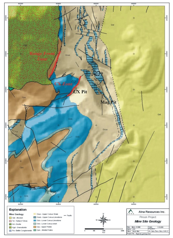
Figure
7-4. Mine Site Geology
(Source:
Atna Resources, March 2005)
8.0 Deposit
Type
8.1 Sediment-hosted,
▇▇▇▇▇▇-type Gold System
Gold
mineralization at the ▇▇▇▇▇▇ Mine is considered to be typical
of ‘▇▇▇▇▇▇-type,’
or sediment hosted gold deposits.
‘▇▇▇▇▇▇-type’
mineralization was first recognized from discoveries in east-central
Nevada in
the early 1960s (▇▇▇▇▇▇ Mine). Similar deposits had been mined
prior to the
1960s (for example ▇▇▇▇▇▇▇▇, first mined in the 1930s), but
their discovery in
Nevada in 1961, and the recognition of the gold endowment they
represented, has
led to the opening of more than 100 mines, producing about
200 million ounces of
gold, assuring Nevada a leading position in world gold production
(▇▇▇▇▇, 2004,
p. 1).
▇▇▇▇▇▇-type
gold deposits display the following characteristics:
| · |
Gold
occurs primarily as ionic substitution or micron-sized
particles, often in
▇▇▇▇▇▇▇▇ pyrite, locally termed “sooty
pyrite”.
|
| · |
Gold
is hosted primarily by silty limestone to calcareous
siltstone lithologies
in the vicinity of major structural
zones.
|
| · |
Gold
mineralization is concentrated in structural traps
and/or replacement
horizons of receptive permeable
beds.
|
| · |
Subtle
alteration, dominated by decalcification and argillization
of the host
rock, and accompanied by selective silicification
(jasperoid) and
carbon-flooding.
|
| · |
“Gangue”
(non-economic) minerals - calcite (calcium carbonate),
siderite (iron
carbonate), and-ferroan-dolomite (calcium-magnesium
carbonate) - occur as
geochemical fronts at many deposits, but are not
ubiquitous.
|
| · |
“Pathfinder”
elements (Sb, As, Hg) often occur in spatial association
as the minerals
orpiment, realgar, stibnite, or
cinnabar.
|
| · |
Dikes,
although not ubiquitous at some deposits, are characteristic
at most
(▇▇▇▇▇▇▇▇, Goldstrike, ▇▇▇▇▇▇, ▇▇▇▇▇▇▇ Canyon) and
occupy many of the
mineralized fault zones in the
deposits
|
Mass-balance
analysis of plausible chemical reactions in individual deposits
has led to a
belief that (1) fluid-wallrock interactions and (2) sulfidation
of reactive iron
are important deposit-scale mechanisms of mineralization. Although
this chemical
feature is well-documented (Hofstra and ▇▇▇▇▇, 2000; ▇▇▇▇▇▇▇
et al., 1998), the
underlying reason for it is not.
Except
for the gold-▇▇▇▇▇▇▇▇ pyrite association, other features of
▇▇▇▇▇▇-type systems
do not seem to be characteristic of a particular process (such
as banded veins
in epithermal systems) that would tie into a genetic explanation
for the
occurrence of the system (Seedorff and ▇▇▇▇▇▇, 2004). The deposits
require
sources of heat, gold, sulfur, and iron; a means of fluid transport;
and
receptive rocks. The receptive rocks, fortunately, exist over
a large area of
east-central Nevada, as explained earlier in the general review
of Paleozoic
stratigraphy. There are numerous occurrences of telescoped
overthrust sections,
both older-over-younger and younger-over-older, which place
potential ore hosts
in a variety of complex structural and stratigraphic settings,
which create a
variety of traps, and large regional structures cutting through
these sections
that serve as pathways for circulation of hydrothermal fluids.
One
enigma remains the heat source. Both magmatic and metamorphic
sources have been
discounted, as there seems to be no direct age relationship
to major stocks, and
regional metamorphism would have likely occurred in the Late
Cretaceous or
Earliest Tertiary, when plate collisions, underthrusting of
continental slabs
and crustal-thickening events were active. Two theories are
gaining currency,
though:
| 1. |
Regional
Eocene magmatism was probably a major source of thermal
energy throughout
the ▇▇▇▇▇▇-type province (▇▇▇▇▇▇▇▇ and ▇▇▇▇▇▇,
2004);
|
| 2. |
Basinal
mechanisms, which rely on the onset of Basin-Range
extension to create
crustal permeability, could have facilitated the
widespread circulation of
heated meteoric water (Seedorff and ▇▇▇▇▇▇,
2004).
|
Ambiguous
igneous and radiometric evidence exists to lend support to
either of the above
hypotheses: presumed Tertiary dikes occur at many of the deposits,
and a great
number of deposits have been dated at 39-42 Ma (Arehart et
al.,
2003).
9.0 Mineralization
Past
production focused solely on oxidized ore. Oxidation is extensive
in the
CX-▇▇▇▇▇▇ fault system, affecting the entire length of the
zone and penetrating
up to 1500 feet in depth. The oxidation process generated pervasive
limonite,
hematite, and other iron and arsenic oxides. Oxidation is variably
developed in
the Range Front fault. In some fault and shear zones, oxidation
is present at
depths of 1800 feet; in other places oxidation gives way at
shallow depths
(<500 feet) to sulfide mineralization.
Sulfide
mineralization is a pervasive event consisting of two stages
of pyrite
development, a non-ore pyrite, and an ore-stage ▇▇▇▇▇▇▇▇ pyrite.
In hand
specimens, gold bearing pyrite is a dull brassy to black color
and extremely
fine-grained. Remobilized carbon is usually associated with
the pyrite, giving
the sulfides a “sooty” appearance. Gold is primarily contained in pyrite, or
found as rims around fine pyrite grains (▇▇▇▇▇▇▇
and Wittkopp, 1983,
▇▇▇▇▇▇,
1994). Detailed geochemical work suggests there is also a primary
positive Au-Hg
(and weaker Au-As) correlation, as well as a negative Au-Ba
association, which
is preserved in the unoxidized environment (▇▇▇▇▇▇ and ▇▇▇▇▇▇▇▇▇▇,
1991). No
other major elements (Pb, Zn, Cu, Mo, F) show any positive
or negative relation
to Au.
9.1 Host
Rocks
The
environments being targeted for continued exploration are shown
in three
representative cross sections which span the area of the current
resource
calculation and structures under study:
| · |
Section
6800 NE (Appendix
9-1)
shows the principal relationships involving the CX
fault and related
strands.
|
| · |
Section
7100 NE (Appendix
9-2)
is 300 feet further NE along strike of the CX fault
zone, and picks up the
definable beginnings of the Range Front fault
zone.
|
| · |
Section
7700 NE (Appendix
9-3)
is
another 600 feet further NE along the same trend,
and shows principally
the Range Front fault zone.
|
In
all
three sections, several features of stratigraphy and structure
are
evident.
Host
rocks for gold mineralization at ▇▇▇▇▇▇ are a sequence of interbedded
shale,
siltstone, and limestone of the Upper and Lower Comus Formation
of Ordovician
age. These rocks are exposed in outcrop and the mine pits along
the east flank
of the ▇▇▇▇▇▇ Mountains. The Upper Comus is a gently east-dipping
complex
consisting of black carbonaceous shale interbedded with varying,
but minor,
amounts of calcareous siltstone and silty limestone. Beneath
the Upper Comus
lies a large volume of rock assigned to the Lower Comus, which
consists of a
monotonous sequence of interbedded shale and limestone in roughly
equal
proportions. Local variations in the Upper and Lower Comus
have been assigned
unit names of “Ocls” and “Ocib” depending on relative abundance of limestone
versus shale.
Within
the Lower Comus interbedded shale/limestone unit, there are
large irregular pods
of Ordovician contact-metamorphosed carbonates, ranging from
pure marble to
garnet-epidote skarn to calc-silicated, wollastonite-dominated
rocks. These are
combined as skarn/marble (“Osm”) and shown separately on the cross-sections.
Finally, the lowest defined stratigraphic unit is the Cambrian
▇▇▇▇▇▇,
ordinarily a maroon colored hornfelsed phyllite in the ▇▇▇▇▇▇
mine
area.
Structurally,
the cross-sections are dominated by two large fault systems.
The CX fault zone,
appearing on 6800 NE and 7100 NE, is a zone of brittle fracture
within the Ocib
package, and creates one dominant and several narrower splays
of mineralization.
The Range Front fault zone (displayed on cross-sections 7100
NE and 7700 NE), in
contrast, is much thicker and persistent, and involves the
Cambrian/Ordovician
contact zone in extensive brecciation. On the sections, the
contact zone is
represented as a single line, but in reality is obliterated
in many core
intercepts by a broad zone of shearing.
Internally,
the rocks display a significant degree of ductile deformation
of undetermined
age. Numerous instances of necking, rotation and dismembering
of beds, polished
slip surfaces, healed discontinuities and sheath folding are
evidence of
deformation under high confining pressures, and mask less extreme
features, such
as debris-flows and related soft-sediment deformation.
9.2 Alteration
Alteration,
consisting of silicification, decalcification, argillization,
introduced carbon
and pyrite, is enhanced along structural zones. Primary alteration
associated
with the gold mineral system has been affected by a later stage
of oxidation,
with or without the development of clay fracture-fillings and
veinlets.
The
alteration suite at ▇▇▇▇▇▇ displays features common to other
▇▇▇▇▇▇-type,
sediment-hosted environments. Historical accounts of the Pinson
Mine (▇▇▇▇▇▇▇▇▇
et al., 2000) describe alteration found along the CX and MAG
faults.
In
the CX
environment, which includes the A, B, C, CX and CX West pits,
there were
gradational changes in the style and intensity of alteration.
Beginning in the
southwest, the B Pit was noted as a faulted interface between
carbonates and
argillites, with gold deposition occurring in weakly silicified
and kaolinized
fractures. Nearby, the A Pit was dominated by the development
of gold-rich
jasperoid (silicification of limestone-dominant rocks); within
it, arsenical
pyrite contained inclusions of <5 micron free gold. Accessory minerals were
chalcedony, kaolinite, marcasite, pyrite and sericite. Further
northeast, the C
Pit hosted ore in decalcified carbonates cut by small cross-faults.
The
CX
Fault Zone, developed in the CX Pit, was characterized by a
swarm of subparallel
fault strands containing silica-pyrite replacements along narrow
zones of
carbonate. Silicification was more prevalent here than in the
Range Front zone.
A large volume of the adjacent hangingwall carbonate was thoroughly
decalcified,
but barren. Broad pervasive zones of alteration are not present
within the CX
mineral zone. Argillization and calcite veining occur in and
adjacent to the
fault zone. In many instances the fault breccia matrix has
been completely
argillized (▇▇▇▇▇▇▇▇▇▇, 1983). A deep core test undertaken
in 1993 (DDH-1541)
encountered a leached, gold-bearing zone containing marcasite,
arsenopyrite, and
traces of cinnabar, realgar, stibnite, sphalerite, galena and
native arsenic.
The CX West Pit, a fault zone parallel to but 600 feet west
of the CX, hosted
ores extracted from the faulted contact zone separating lower,
calc-silicated
Comus carbonates from Upper Comus argillites.
The
MAG
pit developed near the projected intersection of the north-northwest
trending
MAG fault and the northeast trending CX fault. Certain lithologies
(calcareous
argillite and shale) were preferentially mineralized relative
to others (pure
argillite and calc-silicates). The dominant alteration elements
were total
decalcification and leaching of the carbonate host, accompanied
by extensive
argillization. Pervasive silicification healed fault ▇▇▇▇▇
and breccias,
produced jasperoids in the leached rock, and replaced undisturbed
rock adjacent
to the silicified structures.
The
Range
Front fault zone, in contrast to the CX-related system, displays
primarily
pervasive argillization and decalcification of the host rock.
Where strongest,
the zones consist of punky, spongy decalcified limestone in
an argillically
altered shaley, silty matrix. White and ▇▇▇▇▇ ▇▇▇▇ fracture-
and void-fill
veinlets and patchy zones occur which give the rock a mottled
appearance.
Silicification appears minor and occurs as a broad overprint,
perhaps related to
diagenesis, or as altered clasts in breccia zones. Calcite
veining is prevalent
throughout the system but is strongest along the margins of
the Range Front
fault envelope.
In
the
Atna exploration program to date, mineralized core holes in
both the CX and
Range Front (RF) zones encountered the alteration features
typical of past
▇▇▇▇▇▇ mining experience, and expected in ▇▇▇▇▇▇-type systems,
as detailed
below:
Table
9-1: Inventory of Alteration Types in Atna Phase I Drilling
|
Alteration
Type
|
Example
CX Holes
|
Example
RF Holes
|
|
Weak
silicification
|
201,
204
|
208,
215, 223, 229A
|
|
Strong
silicification
|
204,
206, 211, 213, 216, 219
|
209,
212, 221, 227, 230
|
|
Decalcification
|
206,
216
|
212
|
|
Argillization
|
203,
204, 211, 216, 220
|
202,
209, 212, 215
|
|
Carbon
flooding
|
216,
219, 226
|
202,
221, 225
|
|
Secondary
pyrite
|
219,
226
|
202,
207, 215, 221
|
|
Orpiment
& realgar
|
226
|
202,
215, 223, 228
|
|
Oxidation
|
203,
219
|
230
|
|
Brecciation
|
204,
211, 216, 219, 220
|
205,
207, 209, 210, 212,
215,
221, 222, 223, 225
|
9.3 Mineralized
Zone Configuration
Figures
9-1 and 9-2 show grade thickness contours defining the current
known morphology
of the CX and Range Front Fault mineralized zones in longitudinal
section. The
sections are oriented approximately N30E, with the left edge
southwest, the
right edge northeast, and the section dipping toward the viewer
at 55 degrees.
The sections represent the grade multiplied by the thickness
of mineralization
along the strike of the fault plane. ▇▇▇▇▇▇ Mining Company
drill holes are shown
in green and recent Atna Resources drilling shown in yellow
ochre.
The
CX
mineral zone (Figure 9-1) is the smaller of the two, with an
approximate strike
length of nearly 2000 feet and an overall down-dip extent in
excess of 1500
feet, with grades averaging better than 0.25 oz/ton. From the
section it can be
seen that mineralization is poddy near the surface, with three
separate zones of
mineralization at and just below pit level. Below about 4500
feet in elevation,
mineralization becomes more consistent, with two separate bodies
in evidence.
Both extend down dip over 600 feet, with strike lengths of
300 to 500 feet.
These two zones are separated by a weak to non-mineralized
zone. Causes for this
barren zone are not fully understood, but post mineral faulting
is a likely
cause.
Atna
Resources’ drill program in the CX was designed to define the extents
of the
southern mineral zone, and firm up the potential down dip extent
in the northern
mineral zone. Holes APCX-226, 224, 218 and 216 limited the
extent of the
southern mineral zone on the south and north edges, helping
to refine the barren
zone between the north and south zones. Hole APCX-219, arguably
the best Atna
drill hole into CX mineralization, added significant width
and grade potential
to the northern mineral zone. This hole also helps define a
roughly 20 degree
northeast oriented rake in thicker, higher grade mineralization.
This thicker
zone remains open at depth to the northeast.
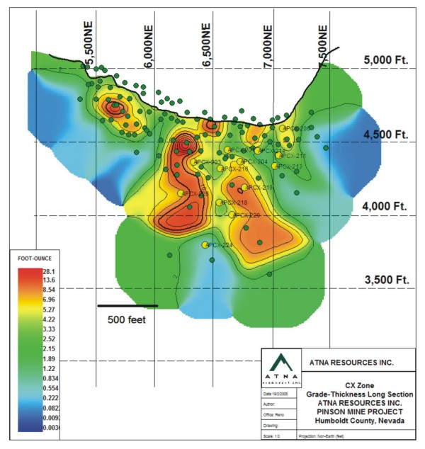
Figure
9-1. Grade-Thickness Long Section, CX Fault Zone
(Source:
Atna Resources, March 2005)
Mineralization
along the Range Front Fault, in contrast to the CX Fault, appears
to be more
consistent (Figure 9-2). Drill spacing in the Range Front system
is broad at
this stage, but what appears to be developing is a near vertical
zone of
mineralization from about 4700 feet in elevation, down to approximately
3500
feet, with grades greater than 0.1 oz/ton gold. In the early
stages of
exploration, this columnar area appears to consist of two connected
zones below
4400 feet, and a separate zone above 4500 feet. The area between
the zones is
weakly mineralized (see APRF-215), and may represent post-mineral
offset along
the CX West Fault, an ENE trending, west-dipping fault.
Prior
to
Atna’s program, mineralized intercepts in the Range Front zones
were sparse,
with holes spaced 400 to 600 feet apart. Atna’s program was designed primarily
to fill in between these intercepts and step out from known
thick high grade
intercepts in holes HPR-050, HPC-162, HPC-144, and HPC-075
drilled by Homestake
Mining Company (HMC) as operator of the Project for the Homestake/Barrick
partnership. Atna’s program has begun to define an upper zone of mineralization
with offsets of hole HPR-050 that carry mineralization up dip
almost 300 feet to
hole APRF-207, 400 feet to the southwest (hole APRF-209), and
200 feet southeast
in hole APRF-212. Atna drilling at deeper elevations is also
beginning to define
a zone of mineralization surrounding holes APRF-225 and APRF-223.
These two
holes were drilled 400 feet downdip of hole HPR-050, halfway
to intercepts at
depth in HMC holes 144, 162, and 075. Hole APRF-221, targeted
within the
triangle defined by the last 3 holes, confirmed continuity
of mineralization
among these holes.
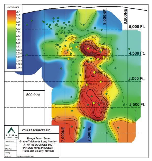
Figure
9-2. Grade-Thickness Long Section, Range Front Fault Zone
(Source:
Atna Resources, March 2005)
As
in the
CX mineral zone, an apparent rake is developing in the thicker,
higher grade
intercepts which plunges NE from 10 to 30 degrees. The rake
in both the CX and
Range Front zones probably represents the trend and plunge
of intersections
between fault planes and favorable lithologic horizons.
10.0 Exploration
10.1 Introduction
Exploration
approaches at ▇▇▇▇▇▇ have consisted primarily of mapping, geochemical
sampling
and drilling. These approaches have been successful in discovering
about 1
million ounces of gold in several exploited open pit deposits.
Several
geophysical approaches have been applied with limited or non-measurable
success.
Geophysics has largely been applied to exploratory programs
along strike of
known mineralized zones and as grass-roots applications to
find additional
mineralized zones.
10.2 Geologic
Mapping and Geochemical Sampling
Cordex
Syndicate, and its successor, ▇▇▇▇▇▇ Mining Company, explored
the property
largely through mapping and geochemical sampling. There are
three known mapping
programs:
|
1)
|
A
regional mapping program from ▇▇▇▇▇▇ to ▇▇▇▇▇▇▇▇
by ▇▇▇▇ ▇▇▇▇▇▇▇ in the
late 1970s. The map has yet to be recovered from
the ▇▇▇▇▇▇ property
archives.
|
|
2)
|
A
1:6000 scale mapping program of the ▇▇▇▇▇▇ property
in 1983. Portions of
the map series have been located in ▇▇▇▇▇▇ property
archives.
|
|
3)
|
A
1:2400 scale mapping program of the Pit areas through
the active life of
the mine. Portions of the map series have been located
in ▇▇▇▇▇▇ property
archives.
|
In
addition, bench mapping in the pits occurred during mining,
and was followed up
by detailed 1:1200 scale maps of the A, B, C, CX, MAG, CXW,
and Bluebell pits by
▇▇▇ ▇▇▇▇▇▇▇▇ in 2000, after the cessation of mining activities.
▇▇▇▇▇▇▇▇’▇ maps
were completed under the Homestake Mining/Barrick partnership
agreement.
Several
geochemical programs were completed by the Cordex Syndicate
and ▇▇▇▇▇▇ Mining
Company during early discovery of the ▇▇▇▇▇▇ Mine, throughout
active mining, and
by Homestake Mining Company. These are:
|
1)
|
Cordex
Syndicate took rock chip samples during ongoing mapping.
A total of 737
samples were taken in this program. Samples were
assayed consistently for
gold, silver, arsenic, antimony, and mercury, with
select samples also
analyzed for lead, zinc, copper, and manganese. The
dual programs of
sampling and mapping were responsible for the discoveries
of the Blue Bell
and ▇▇▇▇▇ Canyon pit areas (▇▇▇▇▇▇▇▇ et al.,
2000).
|
|
2)
|
Pinson
Mining completed 6 float chip geochemical grids consisting
of 8,756
samples. These grids cover the MAG deposit, and on
strike to the south of
the A and B pits.
|
|
3)
|
A
biogeochemical study of sagebrush was run in the
1990s. Results from this
study were inconclusive.
|
|
4)
|
312
additional rock samples and 273 additional soil samples
were taken under
the Homestake/▇▇▇▇▇▇▇ ▇▇ program. These sample programs
were completed on
strike to the south of the existing pit areas, and
to the west of the A,
B, C, and CX pits, near the Granite Creek Tungsten
Mine.
|
10.3 Drilling
There
are
several generations of drill programs on the property, beginning
in 1963 with
Nevada Goldfields Corporation’s drilling program.
1) Reverse
circulation drilling by Nevada Goldfields Corporation in the
1960’s to prove up
a small resource in the “B” pit area.
|
2)
|
A
2-hole program (core) by Homestake Mining Company
in
1968.
|
|
3)
|
Exploration
and development drilling by the Cordex Syndicate
and ▇▇▇▇▇▇ Mining Company
from 1970 to 1996. This program led to the initial
discovery of the A, and
B pits, and led to successive discoveries of the
C, CX, and Mag Pits.
Within the Atna-▇▇▇▇▇▇ Mining Company Area of Interest
there are 2,323
holes, totaling 1,063,734 feet, drilled by the Cordex
Syndicate or ▇▇▇▇▇▇
Mining Company.
|
|
4)
|
A
206-hole program by Homestake Mining Company from
1997 to
2000.
|
|
5)
|
A
3
hole program by Barrick during
2003.
|
|
6)
|
Atna
Resources completed 31 drill holes, a combination
of reverse circulation
rotary and diamond drilling from August 2004 through
February 2005
totaling 29,740.5 feet of drilling
|
|
7)
|
Miscellaneous
exploratory holes in the area include a twelve hole
program by Echo Bay
Exploration, scattered holes by the USGS for research
purposes, and
numerous drill holes in and around the Granite Creek
and Pacific Tungsten
Mines.
|
Homestake
Mining Company’s activities from 1997 to 2000 were the last extensive effort
to
explore for gold on the property, resulting in the identification
of deeper high
grade gold resources in the CX and Range Front Fault Zones
which have been the
focus of Atna’s exploration and resource definition work.
10.4 Trenching
and Channel Sampling
No
trench
or channel sample programs are known.
10.5 Geophysics
Numerous
geophysical surveys have been completed during the course of
activity at ▇▇▇▇▇▇.
These include regional and detailed surveys. Regional surveys
include gravity
and aeromagnetics. Detailed surveys run were mostly electromagnetic
in nature
and include IP, EM, MT, and CSAMT surveys. A brief summary
includes:
|
1)
|
Airborne
EM and magnetics by the USGS at ¼ mile spacing throughout much of the
▇▇▇▇▇▇▇▇ Trend.
|
|
2)
|
Ground
based magnetics covering the CX zone completed in
1970 by the Cordex
Syndicate.
|
|
3)
|
Regional
gravity surveys, both public and private, compiled
by Homestake Mining
Company in 1997.
|
|
4)
|
Ground-based
magnetic survey at the north edge of the MAG pit
completed in 1998 by
Homestake Mining Company.
|
|
5)
|
Several
generations of AMT (EM, IP, CSAMT) completed by ▇▇▇▇▇▇
Mining
Company.
|
|
6)
|
Several
CSAMT lines completed by Homestake Mining Company
in 1998 to
2000.
|
|
7)
|
Several
EM lines completed by Homestake Mining company in
2000
|
Technical
reports and data sets are available for these surveys. No interpretive
reports
have been located. The geophysical surveys previously completed
at the project
have not been utilized by Atna as part of its exploration efforts
to define
mineralization associated with the CX and Range Front mineral
zones.
10.6 Underground
Drifting / Evaluation
A
small
exploration drift was put into the upper “B” zone by Cordex Syndicate in the
early 1970s for bulk testing. Results are unknown, as no report
has been found
in the ▇▇▇▇▇▇ property archives.
11.0 Drilling
11.1 Summary
of Past and Present Programs
11.1.1 Drilling
by Earlier Operators
A
total
of 2,325 holes have been drilled inside the Atna-PMC JV agreement
area. ▇▇▇▇▇▇
Mining Company, or ▇▇▇▇▇▇’▇ predecessors - Rayrock Mines and the Cordex
Syndicate - drilled the majority of those holes (2,100), while
Homestake Mining
Company drilled 206 targeted holes. Holes drilled by other
companies are
scattered about on the property, including 4 by Barrick, 12
by Echo Bay at the
north end of the property, and numerous holes drilled prior
to 1970. The digital
database, initially established by Homestake Mining Company,
had been set up to
track only HMC data from 1997 on. All data prior to 1997 was
lumped into “OTHER”
in the Drilled_By field, negating any method for tracking who
drilled any
particular hole. Table 11-1 Summary of Previous Drilling, provides
the digital
record of the previous known drilling activity on the property.
Table
11-1: Summary of Previous Drilling.
|
Drilled
By
|
#
of Holes
|
Total
Footage
|
Average
Depth
|
|
HOMESTAKE
|
206
|
236,255
|
1147
|
|
OTHER
(PMC or Others)
|
2119
|
1,072,320
|
395
|
The
vast
majority of PMC holes were development holes in and around
the existing pit
areas. There are over 1200 drill holes within the A, B, C,
CX, MAG, CXW, ▇▇▇▇▇,
and Bluebell pit areas. All but 9 are either conventional or
reverse circulation
rotary drill holes, and most (778) were drilled vertically.
All of the 9 core
holes drilled by ▇▇▇▇▇▇ Mining are in the B, C, CX, and Mag
pit areas, and
served one or more of the following purposes; stratigraphy,
metallurgy, or deep
tests on mineralized structures. A nearly complete set of original
drill logs is
available in the archives of ▇▇▇▇▇▇ Mining Company at the ▇▇▇▇▇▇
project
site.
Homestake
Mining Company drilled 206 holes on the property with the vast
majority (146)
focused on the CX and Range Front Fault systems, accounting
for 134,000 feet of
the total HMC footage. Forty of these holes were drilled either
entirely as HQ
core, or as reverse circulation pre-collars with HQ core tails.
The rest,
including pre-collared portions of core holes, were drilled
by reverse
circulation methods. All original HMC drill logs are available
onsite.
▇▇▇▇▇▇▇
Gold Exploration drilled three holes in 2003 to test targets
identified
subsequent to ▇▇▇▇▇▇▇’▇ acquisition of Homestake Mining. Drilling tested the
deep (>3,000 feet) extensions of the CX fault zone near its projected
intersection with the fault zone controlling mineralization
in the Mag
Pit.
11.1.2 Drilling
by Atna Resources
Atna’s
program followed up the drilling by both ▇▇▇▇▇▇ Mining Company
(PMC) and
Homestake Mining Company (HMC) that identified the mineral
zones beneath the CX
pit and along the Range Front Fault. As part of its due diligence
to define a
mineral resource, Atna drilled 31 holes, totaling 29,740.5
feet of combined RC
and core, to test previously drilled mineralization in the
two primary targets.
Atna’s program had four-objectives:
| 1. |
To
prove existence of the mineralized zones in terms
of grade and thickness,
particularly in regions where the only information
available was reverse
circulation drilling.
|
| 2. |
To
develop continuity to the mineral zones by drilling
between known
intercepts, particularly in areas where intercepts
were greater than 400
feet apart.
|
| 3. |
To
establish size limits to known mineralized bodies,
especially in areas
where marginal and potential economic intercepts
coexisted.
|
| 4. |
To
obtain rock quality data on hangingwall, foot wall,
and mineralized zones
to plan future underground exploration, reserve definition
drilling
platforms, and bulk sampling
programs.
|
Of
the
29,740.5 feet of drilling completed by Atna Resources Inc.,
13,000 feet in 13
holes were drilled into the CX Fault zone and 16,740.5 feet
in 18 holes were
drilled into the Range Front Fault zone. (The prefixes APCX-
and APRF- indicate
the CX and Range Front targets, respectively) Table 11-2 Summary
of Atna
Resources Phase I Drilling, summarizes the drill holes by depth,
RC footage, and
core footage. Both the CX and Range Front faults are NE striking,
SE dipping
faults. Consequently, all of Atna’s drill holes were oriented to the WNW, around
300 degrees azimuth, and angled from 45 degrees to 75 degrees.
Coring began
between 100 to 200 feet above the fault zones and terminated
usually from 50 to
100 feet after the footwall zone of the fault was encountered.
Atna’s
area of immediate focus within the CX Fault zone and southern
portion of the
Range Front Fault zone contains numerous shallow drill holes
(see Table 11-1),
but only 370 drill holes from PMC and HMC actually ▇▇▇▇▇▇ the
fault zones. The
majority of holes drilled by PMC within Atna’s Phase I exploration area have
either been mined out, or are too short to ▇▇▇▇▇▇ the fault
structure.
11.2 Drilling
methods
Atna’s
program utilized both reverse circulation (RC) and diamond
core drilling (DDH)
methods. Reverse circulation drilling was used primarily as
pre-collars for
diamond core tails. This was done to minimize costs in the
barren material above
the mineralized fault zones. Diamond drilling was utilized
to provide better
confidence in sample quality than can be expected from RC drilling
methods, as
well as to provide for rock quality calculations and better
geologic definition
of the structurally controlled ore zones for engineering and
modeling purposes.
The distribution of reverse circulation versus core holes is
discussed in
Section 17.3 of this report.
Table
11-2: Summary of Atna Resources Phase I Drilling
|
Hole
Number
|
Total
Depth
|
RC
Footage
|
Diamond
Footage
|
|
APCX-201
|
440
|
0
|
440
|
|
APRF-202
|
788.5
|
0
|
788.5
|
|
APCX-203
|
845
|
400
|
445
|
|
APCX-204
|
980
|
385
|
595
|
|
APRF-205
|
674
|
385
|
289
|
|
APCX-206
|
222
|
0
|
222
|
|
APRF-207
|
635
|
635
|
0
|
|
APRF-208
|
1,090
|
700
|
390
|
|
APRF-209
|
676
|
350
|
326
|
|
APRF-210
|
645
|
400
|
245
|
|
APCX-211
|
1,010
|
500
|
510
|
|
APRF-212
|
980
|
600
|
380
|
|
APCX-213
|
1,100
|
700
|
400
|
|
APCX-214
|
1,020
|
600
|
420
|
|
APRF-215
|
1,010
|
600
|
410
|
|
APCX-216
|
1,045
|
460
|
585
|
|
APRF-217
|
920.5
|
600
|
320.5
|
|
APCX-218
|
1080
|
700
|
380
|
|
APCX-219
|
1,160
|
800
|
360
|
|
APCX-220
|
1248
|
970
|
278
|
|
APRF-221
|
▇▇▇▇
|
▇▇▇
|
▇▇▇▇
|
|
APRF-222
|
650
|
650
|
0
|
|
APRF-223
|
1300
|
1000
|
300
|
|
APCX-224
|
1439
|
1060
|
379
|
|
APRF-225
|
1387
|
1080
|
307
|
|
APCX-226
|
1412
|
1100
|
312
|
|
APRF-227
|
780
|
260
|
520
|
|
APRF-228
|
500
|
500
|
0
|
|
APRF-229
|
432
|
432
|
0
|
|
APRF-229A
|
1515
|
1045
|
470
|
|
APRF-230
|
924.5
|
700
|
224.50
|
|
Total
Drilled
|
29,740.5
|
18,412
|
11,328.5
|
11.2.1 Reverse
Circulation Rotary Drilling
The
RC
drilling conducted by Atna was completed by ▇▇▇▇▇▇ Construction
& Drilling
of Winnemucca, Nevada using a ▇▇▇▇▇▇▇ 1500 truck mounted drill,
supported by a
water truck, pipe truck, and service truck, and staffed by
a driller, helper and
sampler.
RC
drilling was used principally for pre-collaring core holes.
The pre-collar
portion consisted of drilling through non- or weakly-mineralized
rock and
stopping at a known depth above target mineralization. After
drilling, the hole
was cased using 4 5/8 inch threaded steel pipe to maintain
the integrity of the
hole until the core rig arrived to finish the hole to target
depth.
Drilling
started out using a 5 5/8 inch hammer bit. The hammer bit used
a pounding action
along with rotation to break the rock into pieces, and air
pressure to lift the
cuttings up out of the hole, and into the sample splitter.
When the air system
was no longer powerful enough to drive the hammer in the presence
of high
downhole water pressure, the hammer bit was replaced with a
tri-cone bit. A
tri-cone uses three rotating wheels with pointed carbide buttons
to grind the
rock into little pieces. Air pressure is used, as with the
hammer bit, to lift
the ground-up cuttings to the sampling apparatus.
11.2.2 Diamond
Core Drilling
The
diamond core program conducted by Atna was completed by two
contractors, ▇▇▇▇
Drilling of ▇▇▇▇▇ Fork, Idaho and ▇▇▇▇▇ ▇▇▇▇▇▇▇▇▇▇▇ of Chandler,
Arizona.
▇▇▇▇
used
an LF-1500 truck-mounted drill capable of depths up to 1500
feet with HQ rods,
and 2000 feet with NQ. The rig was suitable for the shallower
core tails, up to
about 1400'. For deeper holes (up to 1800') it was necessary
to resort to a
▇▇▇▇▇▇▇▇ 3000 truck-mounted rig, capable of drilling to 3000’ with HQ rods. This
rig was provided by ▇▇▇▇▇ ▇▇▇▇▇▇▇▇▇▇▇. Both contractors staffed
their rigs with
a minimum of two (driller and helper), and added a water-truck
driver for deeper
holes.
Coring
was completed using HQ triple and dual tube extraction methods.
In triple-tube
extraction, the rock is cut using a diamond-impregnated bit.
The cut rock is fed
through the center of the bit as drilling deepens and is stored
inside a split
tube contained in an outer core tube. After a run is completed,
a wireline is
dropped down the hole to pull the combined assembly. The triple
tube is then
extracted from the outer core tube by using hydraulic pressure
to force the
triple-tube from the outer tube. Core is recovered from this
tube by opening the
internal split tube and placing the core into the core boxes
for transport,
logging, and storage. This method ensures a greater degree
of rock integrity,
allowing for better lithologic, structural, and rock quality
designation (RQD)
descriptions of the rock. Standard dual- tube extraction of
core follows the
same procedure, except that the core retrieval is accomplished
using just the
outer tube of the above configuration, and is extracted by
direct pumping of the
cylinder of drill core itself, or by pounding the rock out
of the tube. In
highly fractured zones this often leads to degradation of intact
core.
11.3 Logging
11.3.1 Reverse
Circulation Rotary Chip Logging
Reverse
circulation chips were collected by the drill sampler in 20-compartment
plastic
trays with recloseable lids, and brought to a logging trailer
for examination
under a standard binocular microscope. Each compartment contained
a
representative amount of drill cuttings from a 5-foot sample
run. Gross
lithologic types, alteration and other features were noted
on the logs. A
schematic graphic log was also drawn to aid the reader in interpretation
of
gross lithologic variations. Breaks in lithology and/or alteration
were noted by
drawing lines across the log sheet at the appropriate footage(s),
with the
depths of the breaks noted at the line. Sample numbers were
plotted alongside
the appropriate footages on the logs as an aid in comparing
lithology and
alteration to assays.
11.3.2 Diamond
Drill Core Logging
At
the
logging facility, the core was laid out, left to right, on
tables for
examination. The core was oriented up-and-down (toward and
away from the
viewer), with the shallowest interval to the lower left and
the deepest interval
to the upper right. Logging tools included bristle brushes
& spray bottles
(to clean core), protractors, scribes, dilute hydrochloric
acid, hand lens,
binocular microscope, and logging forms.
The
logging form includes a logical, visible place to record footage.
Each length of
core marked off by existing core blocks were marked on the
log by drawing a
horizontal line across the appropriate part of the log. The
footage cut and
recovered figure prominently in this record, with entries made
for each "box"
created by the horizontal lines marking footage. Intervals
of no recovery were
indicated by horizontal lines crossing the entire page, and
a blanked-out zone
of 'no information.' Visually, it is instantly obvious on the
log what is
missing and, perhaps, why. This is an appropriate place to
confirm, add or
incorporate the RQD data acquired earlier if it is not being
maintained in a
separate worksheet.
The
logger pays particular attention to accurately documenting
anomalies in footage
shown on the blocks, and accounts for missing core by inserting
blocks
reflecting that, along with a cursory explanation on the block
and a more
substantial explanation on the log itself.
A
graphic
drawing of the lithology is present, to include major rock
types using
conventional or agreed-upon symbols, and the major structural
features of
contact relationships, dip and fractures, accurately plotted
as to angle from
the core axis. Other details of alteration and secondary mineral
suites are
added, as appropriate, and a comment area of the log includes
a description of
the rock that was cut.
12.0 Sampling
Method and Approach
The
objective of the sampling program is to collect a clean, uncontaminated
representative sample that is correctly labeled when drilled
and logged, and
accurately tracked from the drill rig to the assay lab, and
back to the mine
site.
12.1 Sampling
Methods
12.1.1 Reverse
Circulation Rotary
During
the drilling process, cuttings from the bit are sent up the
drill pipe and
initially into a cyclone for homogenization and mixing. From
the cyclone,
cuttings are fed into a rotary splitter that takes a representative
split
(usually a ¼ split), sending one split portion to the sample port, and the
larger through the reject port. Cuttings are placed in 10” x 17” sample bags
that are clearly marked using the drill hole number and a numeric
sequence
prepared beforehand using a spreadsheet. An example of the
sampler’s logging
sheet is included as Appendix
12-1, Sample Sequence).
This
sheet is used to track bag numbers and footages, standards,
blanks, and
duplicates. A small portion of sample is also kept for logging
purposes and is
placed in a chip tray compartment that is clearly marked as
to footage and
sample number.
12.1.2 Diamond
Core Drilling
At
the
rig, core drillers are responsible for obtaining a complete
and representative
sample of the cored interval, generally in runs not to exceed
5 feet and in
shorter increments in difficult conditions. Core is recovered
from the barrel by
using a wireline core tube, if possible outfitted with an inner
'triple-tube.'
12.2 Sample
Quality - Recovery
Sample
recovery for reverse circulation drilling is measured by weight
of material
captured. For a typical 6 inch diameter hole this will usually
result in 8 to 10
lbs. of material on a ¼ split. Core recovery is measured by the ratio of length
of material returned in the tube versus the total length drilled
for the run,
and expressed as a percent.
12.2.1 Reverse
Circulation Rotary
Reverse
circulation sample recovery was excellent, with full 5-10-lb.
bags collected
from every interval of every hole, with the exception of about
15 samples in the
entire Atna set of approximately 6100 samples. The missing
samples occurred in
isolated zones of badly broken ground.
12.2.2 Core
Core
sample recovery was also excellent, in excess of 99% of the
10,000 feet cored.
There were fewer than 60 instances of core loss, each one averaging
less than 2
feet and the vast majority of these losses were due to voids
within the
stratigraphy.
12.3 Sample
Interval
12.3.1 Reverse
Circulation Rotary
The
normal truck-mounted reverse circulation drill in Nevada uses
20’ drill rods,
and the sampler collects 1 sample every 5’. Such was the case with the Atna
drill program. Samples were submitted for assay, as collected
on the rig, in
addition standards, blanks and duplicates were inserted into
the sample sequence
as described below in 12.5, 12.6, and 12.7.
12.3.2 Core
The
typical truck-mounted core rig in the U.S. may be capable of
using a core barrel
up to 10’ in length, but clients will often require the core length to
be
limited to 5’ runs for reasons of sample integrity and to guarantee more
onsite
attention to the hole. The Atna program used a 5’ barrel. All of the core
drilling completed by ▇▇▇▇ - that is, the shallower holes -
was recovered with a
triple-tube assembly, which allows extraction of core from
the inner tube with
less disturbance of the core. A few of the deeper holes in
the program,
completed by ▇▇▇▇▇ ▇▇▇▇▇▇▇▇▇▇▇, were cored with a standard
two-tube assembly,
because triple-tube equipment was not available.
After
the
core is logged, it is the geologist's responsibility to determine
the
appropriate sample intervals. As ▇▇▇▇▇▇ is an underground exploration
target,
the geologist is careful to extract as much analytical information
from the core
samples as possible by adhering to rigid guidelines to better
define boundaries
between likely-mineralized and likely-barren samples. The original
core blocks
used by core drillers to mark the end of a cored run ordinarily
serve as the
primary sample boundary, subject to the rules below; where
a conflict exists
between the blocks and those rules, the rules prevail, and
extra blocks are
inserted by the geologist to compensate:
| · |
A
sample must NEVER cross a lithology
boundary.
|
| · |
A
sample must not cross an obvious alteration boundary,
including
oxidation.
|
| · |
A
sample must not exceed 7 feet in length, and only
be that long if sure to
be barren; 5 feet maximum is
better.
|
| · |
Any
core blocks that do not mark a sample boundary, for
whatever reason (such
as 'cave,', 'loss,' 'void,' etc.), must be labeled
in black magic marker
for photographic visibility.
|
Each
block that marks a sample boundary is outline-highlighted in
red magic marker,
and these interval boundaries are entered on the sample sequence
log alluded to
earlier.
12.4 Sample
Preparation, Quality Control Measures and Security
12.4.1 Sample
Preparation and Quality Control Measures - RC Rotary
Drilling
For
each
drill hole requiring reverse circulation drilling, the drill
crew was provided
with a set of bags prenumbered in sequential order (1 through
XXX). The bags
themselves carried only an exterior designation of drill-hole
number and sample
number. Since the sample numbering sequence includes blanks
and standards
inserted every 10th
sample,
the driller's sampler cannot be expected to keep track of his
sample collection
based on the bag numbering. (Conventionally, RC exploration
either relies on
direct footage, or sample numbers in multiples of 5 feet).
In order to prevent
numeric confusion, yet permit Atna to submit "blind" sample
numbers to the assay
lab, several steps were taken.
First,
the rig sampler was provided with chip trays accurately numbered
with both true
footage and the corresponding bag number. Second, he was provided
with a
deliberately incomplete set of bags; he was deprived of all
the bags intended
for standards and blanks. Third, since the ultimate completed
depth of the hole
is not known in advance, the bags for duplicates (to be collected
every 100')
were merely prelabeled with the letters 'A,' 'B,' 'C,' etc
and flagged with a
tear-off paper tag. The cuttings and tray chips themselves
were collected as a
continuous fraction of the return stream from the drill rig.
The cuttings were
diverted to a 10"x17" mesh bag, and the tray chips were diverted
to a kitchen
strainer. The filled chip trays were collected by an Atna geologist
for logging
under a binocular microscope and remain with Atna, while the
sample bags are
shipped to the analytical laboratory for preparation and assay.
Sample
bags are allowed to dry/drain at the drill site and an Atna
geologist visits the
drill site and confirms the numbering and accuracy of the sample
suite. Samples
are then brought down to the shipment staging area, Atna personnel
then
relabeled the 'A,' 'B,' 'C,' etc. bags (representing the 100'
duplicate samples)
by assigning the correct sequential numbers for them; they
form the tail-end of
the sample list submitted to the lab and therefore are blind
to the laboratory
personnel. The samples are then loaded in 4' x 4' x 3' wooden
crates for pickup
by the laboratory.
12.4.2 Sample
Preparation and Quality Control Measures - Core Drilling
Traditionally,
core is forced out of core tubes by upending the tube, and
tapping on it with a
ball-peen hammer. Exceptionally, to preserve structural integrity,
companies
have requested/required that drillers attach a water line to
the cap of the core
tube and gradually "pump" the core out. This method is often
ignored by the
drill crew in the absence of close supervision. The triple
tube core barrel
eliminates this problem by allowing the interior core container
to be opened
lengthwise. Atna used a triple-tube for all of its shorter
holes completed by
▇▇▇▇ Drilling.
The
core
so obtained was carefully pumped out of the tube assemblies
and laid out on a
rack, intact. The drill crew recorded the Rock Quality Data
(RQD) values on a
worksheet and photographed it, using a digital camera to capture
both the core
and a whiteboard showing hole number and footage interval on
display. For the
deeper holes that did not receive triple-tube treatment and
were therefore
emptied in the traditional way, the geologist later recorded
the most credible
RQD values from core in the core box, and did not photograph
it for RQD
purposes, since it has already been 'broken up' for boxing.
The
RQD
measurement was established by measuring the total length of
all pieces in a
core run that exceed 2x the diameter of the core. In practice,
2x the core
diameter is 0.3 feet. This number was summed, and written as
a numerator in a
fraction where the denominator was the total run drilled. On
worksheets
maintained by ▇▇▇▇, the raw values recorded are the length
of the longest piece,
and the sum of all qualifying pieces within the run Dividing
the former by the
latter yields the numeric RQD.
The
drill
crews placed the core in waxed cardboard core boxes, with tops
and bottoms
accurately labeled as to Company - Property- Hole ID - Box
# -- From - To. The
bottom of the core box was laid out longways from left to right,
with the marked
or labeled end to the left and the unlabeled end to the right.
There are 5 rows
or trays. The first portion of core was laid in the upper left-hand
tray, and
continuously laid in the tray from left to right, advancing
"down" one row as
each tray is completed. The bottom of the core terminated in
the lower right
corner. A wooden block was inserted at the end of each run,
and in locations
deemed important by the drillers to note adverse conditions,
such as caving,
voids, or mislatches (situations where the core tube failed
to seat properly in
the core barrel). The ending block for the run was marked with
an ending footage
on the thin edge, and two numbers on the larger surface:
C
[cut] -
m.n feet R
[recovered] - m.n feet
The
Cut
number results from measured rod footage and the Recovered
number stems from a
taped measurement of core in
situ.
If
the
drillers were not photographing the core, they marked the mechanical
breaks
they made to fit the core in trays with the letter 'M'
on each
side of the break. After boxing, the core was rubber-banded,
a box at a time,
and loaded into vehicles for careful transport to the logging
area, where it was
carefully unloaded and logged).
Each
box
of core, once logged (see 11.3.2, Diamond Drill Core Logging),
was moved to the
deck of the logging trailer for photography on a wooden stand
with a digital
camera, along with a legible placard indicating Hole # and
From - To footage.
After photography, the labeled end of the box top is marked
on the upper right
corner with a large red "P" in Magic Marker.
Since
digital cameras were used for this photography, the quality
of the photos was
checked immediately before the core was disturbed for sampling.
Both the core
box photos taken by the geologic staff and the RQD photos taken
by the drill
crews were downloaded as quickly as practicable, checked for
quality and
clarity, renamed with meaningful file names, and printed out
as 3x5 photos for
archiving in 3-ring binders.
The
geologists provided the sampler with working copies of two
documents: the
geologic core log and the basic sample sequence list, which
contained the
drill-hole number and a continuation of the numeric sequence
carried forward
from the precollar portion of the hole (Appendix
12-1, Sample Sequence).
Although the sampler worked from the sample list itself, it
was useful for them
to be able to see why and how sample boundaries were picked.
It also added a
redundancy check on the geologist's accuracy.
A
decision to saw versus split the core hydraulically depended
on the condition of
the rock and the geologist’s opinion of whether the core was barren or
mineralized. Barren core was generally split with a hydraulic
splitter, for the
sake of speed. Mineralized silicified core was sawn; mineralized
intact
unsilicified core might have been hydraulically split, but
this was not common
(the vast majority of the mineralized core was sawn); mineralized
broken core
was invariably separated and divided equally.
The
sampling operation avoided bias, wherever possible, by dividing
the core in half
perpendicular to the trace of the visible bedding. The portion
to be saved
remained in the core box, in its proper position, with core
blocks in place, and
the box was rubber-banded once again for safety. After the
core was split, the
samples were bagged and boxed in 4' x 4' x 3' wooden crates.
Once logged,
photographed and sampled, the core was palleted, covered with
fitted tarps, and
moved to industrial shelving on an outdoor cement pad for storage
and
reference.
12.4.3 Security
- Reverse Circulation and Core Samples
Crated
samples are delivered to the analytical laboratory in the numbered
bags, along
with a transmittal sheet stating whether the samples are “cuttings” or “core”,
the range of sample numbers, and the total sample count. The
lab has no
knowledge of the spatial reference of the individual samples,
beyond being able
to figure out that sequential numbers from a drill hole represent
top-to-bottom
sampling. In the case of cuttings, they can also infer that
the sample intervals
are 5 feet long (standard in Nevada). In the case of core,
it will be obvious
from the volume that the maximum sample length would be 6 feet,
but there would
be no way of identifying any interval, and many such core samples
will have a
variety of lengths, ranging from 1 foot to 6 feet.
In
addition, because of Atna’s insertion of blanks and standards in the sample
stream, the lab cannot know with certainty exactly what footage
a particular
sample represents. Although forewarned that duplicates are
present, the lab does
not know where they occur in the group. By inspection of the
submitted sample
bag, the lab will be able to identify the blanks (red landscaping
stone) and
standards (pulp powder in Kraft envelopes), and will know that
they occur in
sample numbers divisible by 5, but will have no idea of the
accepted value of
each.
12.4.4 Sample
Preparation
12.4.4.1 On-site
Sample
bags that are intended as Standards and Blanks are labeled
at the logging
trailer, but these particular bags are removed from any numbered
sequence bags
provided to an RC driller at the rig to minimize errors. For
standards, the code
number and grade value is written on the sampler’s sheet at the correct sample
ID value, and inserted into the appropriately marked sample
bag.
Standards
and Blanks, numbered as described above, are inserted in the
crates at a rate of
one standard and one blank for every 20 drill samples (see
12.5 and 12.6,
below).
Each
crate contains the raw samples, duplicates, standards and blanks
intended for
each hole. To the extent possible, all samples for one hole
are aggregated
together, and sample transmittal sheets are filled out in duplicate
(one to the
lab, one for file retention), with one job number assigned
to each hole
shipment.
Atna's
copy of the transmittal sheet is stored in a three-ring binder
in the logging
trailer. Once assays have been received, a copy of the assay
sheets will be
stored with the drill logs and the original with the transmittal
sheets. The
transmittal sheets are indexed by job number.
Copies
of
the sample sequence list, the lithology log and assays are
stored in three ring
binders, indexed by hole number. Originals of all logs and
assays are stored in
file cabinets on a per-hole basis, also indexed by hole number.
Atna personnel
contact the lab to obtain a job number assignment for hole
or partial hole
shipment, and arranges for sample pickup by the lab's driver.
In a number of
cases, an Atna geologist returning to Reno on break may deliver
a crate directly
to the lab.
12.4.4.2 Laboratory
Sample Preparation
BSi
Inspectorate Analytical Laboratories, an ISO 9002-accredited
facility (#37295),
is the primary assay lab for Atna’s ▇▇▇▇▇▇ Project analytical work. Sample
preparation procedures employed by Inspectorate are as follows:
First,
samples are thoroughly dried prior to crushing. Crushing consists
of a two stage
process. Initially samples are sent through a jaw crusher,
and then through a
roll mill to reduce better than 80% of the sample to -10 mesh.
A 300 gram split
is obtained from the coarse reject using a ▇▇▇▇▇ ▇▇▇▇▇▇ splitter.
The split
material is further reduced, with better than 90% of the split
reduced to -150
mesh, using a ring and puck pulverizer.
After
pulverization the sample is sent to the analytical portion
of the lab where a 30
gram sample of the pulp is digested and analyzed for gold using
standard fire
assay methods. Samples are finished using AA, and, for any
sample running over 3
g/t (0.1 oz/t), a gravimetric analysis is also completed.
12.5 Certified
Standard Insertion
To
increase the integrity of the sample handling process, from
collection to
shipment to assay, standards are inserted in the sample stream
at a rate of one
standard for every 20 drill samples. For each group of 20 drill
samples, the
15th
sample
is a standard: standards are therefore numbered 15, 35, 55,
75, etc. The
reference standards were obtained from RockLabs in Elko, and
consisted of a
suite of both oxide and refractory certified powders. RockLabs
also supplied
statistics for the certified standards, shown in Table 12-1,
RockLabs Reference
Material.
Table
12-1: RockLabs Reference Material.
|
Character
|
Sample
ID
|
Accepted
Analytical Value
|
95%
CI
|
Std
Dev.
|
|
Oxide
|
OXE
21,
|
0.651
ppm Au
|
+/-
0.012
|
0.026
|
|
OXN
33,
|
7.378
ppm Au
|
+/-
0.088
|
0.208
|
|
|
OXK
18,
|
3.463
ppm Au
|
+/-
0.058
|
0.132
|
|
|
Sulfide
|
SF
12,
|
0.819
ppm Au
|
+/-
0.012
|
0.028
|
|
SK
11,
|
4.823
ppm Au
|
+/-
0.050
|
0.110
|
|
|
SN
16,
|
8.367
ppm Au, 17.64 ppm Ag
|
+/-
0.087
|
0.217
|
|
|
SP
17,
|
18.13
ppm Au
|
+/-
0.180
|
0.434
|
|
|
SQ
18,
|
30.49
ppm Au
|
+/-
0.350
|
0.88
|
Certificates
for the standards are provided as pdf files in Appendix
12-2 through 12-9.
12.5.1 Protocol
Standards
are stored in plastic bins at the logging trailer. An appropriate
powder from
RockLabs is weighed in lots of 100g and placed in unlabelled,
sealed Kraft
envelopes. The envelopes are then placed in plastic bins individually
labeled
with the code number and gold content. The actual Kraft envelope
containing the
powdered standard is NOT labeled.
When
a
sample shipment is being prepared, standards with different
gold concentrations
are selected randomly from the available group in Table
12-1
and
inserted into the sample stream. A listing of code numbers
and corresponding
values is added to each internally maintained sample list,
archived, and
available to all Atna personnel who deal with sample collection
and
shipping.
Standards
were evaluated based on their variance from the accepted value,
and by
comparison to accepted standard deviations. If any assay from
a standard
exceeded 2 times the accepted standard deviation, the standard
was flagged. If
more than two of the same standard in the same batch failed,
the batch was
flagged. Comparisons to variances from values were checked
continuously for the
standards. Any batches where standards exceeded 10% variance
were flagged and
the assay lab was notified of the issues.
Standard
assays are maintained in the database table, Appendix
12-10,
CHECKS_STANDARDS
12.5.2 Summary
of Results
Standard
evaluation was broken into two sets based on the issues outlined
in section
12.8.2. These issues are very apparent in the AA standards
analyses, but
gravimetric assay comparisons to the standards used are excellent
(Figure 12-1).
Out of 218 standards there were only 18 failures, or a rate
of 1 in 12 (Table
12-2). Two of these failures were either misnumbered bags,
or standards placed
into the wrong bags (APCX-224
215, and APR-210 075), and 4 can be considered actual bad assays
(APRF-227-035,
APR-210-115, APRF-215-015, and APCX-214-075). All other assays
have variances
falling between 10 and 20%, with 5 standards assaying at just
over 10%. An
interesting observation for these standard results is that
contained gold
concentrations of the standards are between 3 and 8 ppm. All
have exceeded the
2x accepted standard deviation flag, however, and have been
considered
failed.
Variances
and standard deviation checks for the 110 AA finish standard
results are poor.
At least 70% of the samples failed the 2x standard deviation
flag, and at least
40 exceed the 10% variance limit. Some of this can be accounted
for. At least 6
standards are affected by out-of-sequence errors. These have
been fixed. Others
include two mislabeled standards (APC-206-035 and APRF-217-135),
and six true
busts.
There
are
2 standards, OXK 18 and OXN 33, which routinely assayed with
variances better
than 10% (7 analyses) but missed the standard deviation flag.
The remaining
analytical problems involve the standards SF12 and OXE21. Accepted
values are
0.891 ppm and 0.651 ppm, respectively. SF12 is a sulfide matrix
while OXE21 is
an oxide matrix. Standard deviations for these two particular
standards are
tight, at 3% each. Except for the 6 true busts all values generated
for these
two standards fall within 20% variance, and often between 10
and 15% of the
accepted value (Figure 12-2).
The
lab
considered the values acceptable, according to its equipment
standards. Since
only two standards are affected by the phenomenon, matrix problems
(improper
digestions or fluxes caused by non-, or weakly-reactive, reagents)
may be the
issue. ALS Chemex has experienced issues with clay-rich matrices
causing
incomplete digestion (▇▇▇▇▇▇ ▇▇▇▇▇▇, personal communication,
2004).
Given
the
problems with standards SF12 and OXE21 it is hard to accept
the values at lower
levels. However these standards only represent assays from
500 ppb to 900 ppb,
at the lower end of the scale of Atna’s current interests. Gravimetric analyses
and AA analyses on standards over 3000 ppb are acceptable and
lend confidence to
the overall quality control program, particularly at the assay
concentrations of
interest to Atna.
Table
12-2: Failed Gravimetric standards
|
Job
|
Sample
|
AU_PPB
|
Au
oz/ton
|
Accepted
value
|
PPB
Variance
|
Oz/ton
for Standard
|
Oz/ton
Variance
|
|
▇▇▇-▇▇-▇▇
|
APCX-226
275
|
3609.00
|
0.12
|
3463
|
4.22%
|
0.10
|
16.83%
|
|
▇▇▇-▇▇-▇▇
|
APRF-229
055
|
3438.00
|
0.12
|
3463
|
-0.72%
|
0.10
|
16.83%
|
|
▇▇▇-▇▇-▇▇
|
APCX-224
335
|
3718.00
|
0.12
|
3463
|
7.36%
|
0.10
|
16.83%
|
|
▇▇▇-▇▇-▇▇
|
APCX-216
215
|
6680.00
|
0.19
|
7378
|
-9.46%
|
0.22
|
-13.10%
|
|
▇▇▇-▇▇-▇▇
|
APRF-227
035
|
20356.00
|
0.26
|
30490
|
-33.24%
|
0.89
|
-70.76%
|
|
▇▇▇-▇▇-▇▇
|
APCX-224
215
|
18280.00
|
0.49
|
7378
|
147.76%
|
0.22
|
129.56%
|
|
104-27-01
|
APR-210
115
|
8190.00
|
0.29
|
7378
|
11.01%
|
0.22
|
33.83%
|
|
▇▇▇-▇▇-▇▇
|
APCX-220
215
|
3900.00
|
0.11
|
3463
|
12.62%
|
0.10
|
10.89%
|
|
▇▇▇-▇▇-▇▇
|
APRF-217
035
|
25821.00
|
0.77
|
30490
|
-15.31%
|
0.89
|
-13.64%
|
|
▇▇▇-▇▇-▇▇
|
APCX-216
035
|
28550.00
|
0.69
|
30490
|
-6.36%
|
0.89
|
-22.86%
|
|
▇▇▇-▇▇-▇▇
|
APRF-215
015
|
7000.00
|
0.21
|
8376
|
-16.43%
|
0.24
|
-14.86%
|
|
▇▇▇-▇▇-▇▇
|
APRF-215
035
|
3690.00
|
0.11
|
3463
|
6.56%
|
0.10
|
10.89%
|
|
▇▇▇-▇▇-▇▇
|
APCX-218
055
|
7765.00
|
0.24
|
7378
|
5.25%
|
0.22
|
10.60%
|
|
▇▇▇-▇▇-▇▇
|
APCX-214
075
|
6596.00
|
0.21
|
8376
|
-21.25%
|
0.24
|
-14.86%
|
|
104-24-99
|
APR-211
115
|
3810.00
|
0.11
|
3463
|
10.02%
|
0.10
|
10.89%
|
|
104-24-60
|
APR-210
075
|
3541.00
|
0.10
|
7378
|
-52.01%
|
0.22
|
-52.60%
|
|
104-23-93
|
APR-208
155
|
7620.00
|
0.10
|
8376
|
-9.03%
|
0.24
|
-59.89%
|
|
▇▇▇-▇▇-▇▇
|
APC-202
015
|
6720.00
|
0.19
|
7378
|
-8.92%
|
0.22
|
-10.78%
|
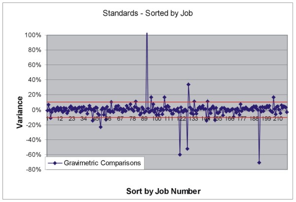
Figure
12-1. Standards Run With Gravimetric Finish.
(Red
lines represent 10% variance)
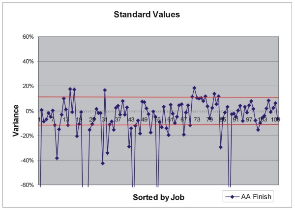
Figure
12-2. Standards Run With AA Finish
(Red
lines represent 10% variance).
12.6 Blank
Sample Insertion
Blank
samples are used for the purpose of checking the primary and
secondary crushing
process at the analytical lab, particularly the adequacy of
equipment cleaning
between samples. Blanks are considered to have failed if they
exceed 2 times the
detection limit of the analytical device. Since Atna has not
used pure blank
material, blanks are considered to have failed if they exceed
20% of the
accepted values as outlined above. Assay are to be re-run if
failure rates
exceed 1 in 5 samples.
12.6.1 Protocol
Commercial
decorative stone purchased commercially in 50-pound bags was
used as the blank
material. The material was stored, in the original packaging,
in a bin outside
the core-logging trailer. One to two 18 oz scoops of material
per sample was
considered sufficient (about 1.2 kg per sample). The material
was placed in
sample bags marked with the appropriate hole number and sample
number for
insertion into the sample stream, then stored with the actual
drill cuttings
prior to shipment. Blanks are inserted into the sample stream
at a rate of one
blank for every 20 drill samples. For each group of 20 drill
samples, the fifth
sample is a blank: blanks are therefore numbered 05, 25, 45,
65, etc'. Blank
samples are inserted into the sample sequence on site and prepped
by the lab
with the actual drill samples.
A
series
of initial assays were completed on the decorative stone to
provide a base line
for analytical values. These results indicate the material,
although not
completely devoid of gold, is sufficiently barren to be able
to discern if
contamination occurs because of improper cleaning techniques
at the lab. Two
separate pulps were created for the gold assays. Table
12-3
lists
the analytical results.
Acceptable
values for the material used to evaluate lab sample preparation
methods for
drill assays are from the clipped column, where the highest
value and lowest
value were thrown out. Ranges of acceptable values are from
less than detection
to 26 ppb (1 standard deviation from the mean). Samples exceeding
the upper end
of the range are considered to have failed.
12.6.2 Summary
of Results
A
total
of 358 blank samples from 63 separate assay jobs were compared
for failure
rates. Of the 358 samples only 21 failed, yielding a failure
rate of 1 in 18 for
the entire program. Of the 63 assay jobs analyzed, only three
jobs contained
samples exceeding the 1 in 5 failure rate for inserted coarse
blanks.
Seven
blank samples from the failed jobs were reviewed. Of those
seven, 2 samples
represented poor cleaning, and the remaining 5 are unknown
failures. The two
samples representing poor cleaning were preceded by high grade
results
(>0.100 oz/ton) and came from the same job. Two other blanks
from this job
were also preceded by high grade samples and passed the failure
rate screen.
These two samples represent an isolated incident.
The
5
failures in question were preceded in sequence by normal drill
assay samples
with gold values less than the blank samples had, and may indicate
contamination
from another step in the assay procedure. However, all other
samples surrounding
the blanks assayed with consistent low grade values and showed
no signs of
contamination spikes. It is entirely probable that the blank
material used has
greater variance in gold concentration than the initial round
of assays on the
material would suggest.
Results
for the blank insertion program indicate proper cleaning procedures
were
followed at the lab, and sample preparation errors have not
influenced assay
results.
Table
12-3: Decorative Stone (Blank Sample) Analysis
|
Decorative
stone Initial analysis - September 9, 2004
|
||||||
|
BSi
Inspectorate Final Report - Job No: ▇▇▇-▇▇-▇▇
|
||||||
|
All
Analyses by fire assay with AA finish
|
||||||
|
|
Run
1
|
|
Run
2
|
|
|
|
|
Sample
Number
|
Au
ppb
|
Ag
ppm
|
Au
ppb
|
|
Combined
Average
|
Clipped
hi-lo
|
|
BWA-001
|
63
|
0.1
|
53
|
58
|
3
|
|
|
BWA-002
|
5
|
0.1
|
10
|
8
|
3
|
|
|
BWA-003
|
6
|
0.1
|
7
|
7
|
2
|
|
|
BWA-004
|
6
|
0.1
|
7
|
7
|
5
|
|
|
BWA-005
|
7
|
0.1
|
12
|
10
|
5
|
|
|
BWA-006
|
-5
|
-0.1
|
-5
|
3
|
3
|
|
|
BWA-007
|
7
|
0.1
|
6
|
7
|
7
|
|
|
BWA-008
|
-5
|
-0.1
|
-5
|
3
|
3
|
|
|
BWA-009
|
-5
|
-0.1
|
-5
|
3
|
3
|
|
|
BWA-010
|
6
|
-0.1
|
-5
|
2.5
|
4
|
4
|
|
BWB-001
|
6
|
-0.1
|
-5
|
2.5
|
4
|
4
|
|
BWB-002
|
8
|
0.1
|
-5
|
2.5
|
5
|
5
|
|
BWB-003
|
45
|
0.2
|
252
|
149
|
17
|
|
|
BWB-005
|
51
|
0.1
|
12
|
32
|
21
|
|
|
BWB-006
|
19
|
0.1
|
14
|
17
|
32
|
|
|
BWB-007
|
18
|
-0.1
|
24
|
21
|
58
|
|
|
BWB-009
|
16
|
0.1
|
-5
|
2.5
|
6
|
|
|
BWB-010
|
13
|
-0.1
|
10
|
|
12
|
|
|
|
|
|||||
|
Average
|
15
|
21
|
19
|
11
|
||
|
Standard
Deviation
|
19
|
60
|
35
|
15
|
||
|
95%
CI
|
9
|
|
27
|
|
16
|
7
|
|
Note:
Less than detection values converted to +2.5 for
statistical
purposes
|
||||||
12.7 Duplicate
Samples - Reverse Circulation Rotary
Duplicate
samples were taken in the field at the drill rig every 100
feet and were used to
evaluate sampling protocols at the rig to ensure adequate representation
of
material was being obtained. Duplicate samples should fall
within 30% of the
original assay with a failure rate not exceeding 1 in 10 samples.
If the failure
rate exceeds 1 in 10 samples then collection methods at the
rig need to be
modified.
12.7.1 Protocol
Duplicate
samples were taken every 100 feet of depth at the drill rig,
with the first
duplicate sample starting at 95-100 foot depth. Samples were
obtained by placing
a 50-50 splitter on the sample port of the rotary splitter
when drilling wet.
Dry drilling required the use of a ▇▇▇▇▇ splitter where the
samples, both assay
and duplicate, were obtained from a 50-50 split of the sample
material from the
cyclone.
Duplicate
samples were inserted at the end of the sample sequence. In
order to maintain a
continuous sequence of sample numbers a second set of sample
bags were labeled
with hole number and “Duplicate A”, “Duplicate B”, etc.. Attached to the bag was
a removable piece of paper with hole number and footage for
the duplicate
sample. This labeling system was necessary because the last
sample number at the
end of the RC portion of drilling was not known until finished.
After RC
drilling was completed, new bags for the duplicate samples
were labeled that
continued the proper numeric sample sequence from the end of
the hole. Duplicate
sample material was then placed into the properly numbered
sample bag for
shipment to the lab. Records were kept on the sampler’s record sheet noting the
footages for each duplicate sample and a cross reference from
the primary bag
label (Duplicate A, etc.) to the actual sample number.
12.7.2 Summary
of Results
Figure
12-3 shows is an x-y pair graph showing a 30% warning line
from a baseline
reference. Samples falling on the high line exceed the 30%
acceptance limit and
therefore have failed the protocol screen. Of the 171 samples
only 5 fall above
the line. This yields a failure rate of 1 in 20.
Two
of
the five samples were determined to have had the bags switched,
either at the
rig by the sampler, or during the relabeling of the bags for
insertion in the
sample sequence. It has not been determined which has occurred.
The other three
samples are due to poor quality control at the rig, with a
poor split as the
likely cause.
Results
from the duplicate program indicate sampling procedures at
the rig are
sufficient to indicate proper representation of the rock sample
is being sent
for assay.
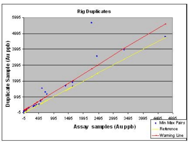
Figure
12-3. Comparison of Duplicate Samples Taken at the Drill vs.
▇▇▇▇▇
▇▇▇▇▇▇.
12.8 Check
Assays of Mineralized Samples
Check
samples were sent to ALS Chemex labs for verification of assays
run by the
primary lab, BSi Inspectorate. A total of 214 samples were
sent for check
analyses. Check assays should fall to within 10% of the original
value if the
original pulp was used for the re-assay, and within 30% if
the check assay came
from a coarse reject duplicate. Failure rates for jobs occur
where less than 90%
of the samples do not fall within the 10% error rate.
12.8.1 Protocol
The
check
assay program consisted of identifying samples with initial
results greater than
0.10 opt gold, and included samples with values less than 0.10
opt gold if they
were part of a mineralized zone with an overall intercept at
better than 0.10
opt gold. After identification, a job order was placed with
the original lab
(BSi Inspectorate) to have the original pulps pulled and sent
over to ALS Chemex
for re-analysis. All check samples were analyzed by ALS Chemex
using a 30 gram
split of the original pulp and run using standard fire assay
techniques with a
gravimetric finish.
12.8.2 Summary
of Results
A
total
of 318 samples were submitted to ALS Chemex as checks on BSi
analytical quality.
At first glance the number of samples exceeding acceptable
error limits is over
the allotment given for failure rates (Figure 12-4).
Figure
12-4 is a plot of sample variance, sorted by grade with higher
grades (values in
ppb) to the right. The red line is the 3000 ppb demarcation
point, and the green
line is the 150 ppb demarcation point. Samples below 150 ppb
Au show extreme
variations, which is understandable at such low concentrations.
Samples between
1000 and 3000 ppb gold show more consistent variation, with
the majority falling
within a 20% error limit. In samples above 3 ppm the variations
become much
tighter, with the majority falling into the 10% error range. The
reasons for the variance are the graph essentially compares
AA finishes from BSi
Inspectorate with gravimetric finishes from ALS Chemex. To
truly check the
validity of the check samples one must separate the data into
two sets, and
eliminate all samples below 150 ppb Au due to the inherent
high variations
generated at such low concentrations of gold.
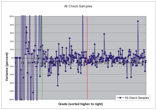
Figure
12-4. Sample Variance of All Check Samples
Eliminating
samples with values below 150 ppb Au leaves 254 samples. Of
these 254 samples
110 represent assays between 1000 and 3000 ppb Au comparing
gravimetric to AA
finishes, and 144 above 3000 ppb Au comparing gravimetric to
gravimetric
finishes. Figure 12-5 shows the checks versus original assay
pairs and a 10%
error level (redline) relative to expected values for the 254
samples above 150
ppb Au (this graph is also a mix of AA-gravimetric comparisons).
Table 12-4
summarizes the results of the two grade intervals.
Table
12-4: Statistics of Lab Variance in AA vs. Gravimetric Finish
|
Grade
Level
|
Number
of samples
|
#
Within 10% Error
|
#
Within 20% Error
|
Rate
below 10%
|
Rate
Below 20%
|
Comparison
Method
|
|
150
- 3000
|
110
|
74
|
21
|
67%
|
19%
|
AA:Grav
|
|
>
3000
|
140
|
120
|
136
|
86%
|
97%
|
Grav:Grav
|
The
graph
shows 56 samples to occur at or above the 10% error level but
only 12 samples
well above the 10% error level. The rest of the samples appear
to hug the line,
falling between 10 and 20% error levels. Since the graph really
is representing
AA versus Gravimetric analyses the errors between 10 and 20%
can be explained by
measurement errors
associated with AA analyses above 8000 ppb, and measurement
errors associated
with gravimetric analyses below about 5000 ppb (errors for
both methods become
larger as the upper and lower thresholds of the equipment are
approached and
exceeded). This would tend to exacerbate the errors in variation
seen between
the two methods.
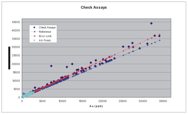
Figure
12-5. X-Y Pair Plot of Check vs. Original Assay, By Grade
To
fully
estimate the percentage errors associated with the two methods
they must be
compared separately. However, for samples between 1000 and
3000 ppb, the
comparisons are still between AA and gravimetric finishes due
to the analytical
methods applied at ALS Chemex. Because these samples may fall
below cutoff grade
it is not as critical to compare these explicitly. Figure 12-6
shows the results
of the samples between 1000 and 3000 ppb Au.
The
red
line on the graph represents the 1000 ppb break, with samples
to the right of
the line assaying above 1000 ppb. Variations left of the red
line consistently
fall within the 20% error level, but a significant number falling
outside the
20% error level also. Variation errors become much less as
higher grades are
encountered, and by 2000 ppb (green line) very few analyses
have greater than
20% variance. As 3000 ppb is approached the variances become
far less, and begin
to fall within the accepted 10% variance level.
In
contrast, assay variations on a gravimetric to gravimetric
comparison are
typically within the less than 10% error limits (Figure 12-7),
even though a
significant number also fall between 10 and 20% variance. The
larger proportion
of these samples assay at less than 8000 ppb, toward the lower
end of
gravimetric finish ranges and may be accounted for by errors
associated with the
gravimetric units at both labs.
Comparing
the gravimetric results from ALS Chemex to the AA results from
BSi Inspectorate
for these samples one finds that sample variance between the
two assays fall
within the 10% accepted limit. This suggests BSi Inspectorate
gravimetric
machinery may not be well calibrated at lower gold concentrations.
Other
considerations such as differences in reagents and fluxes used,
and experience
of the fire assay personnel may also lead to unidentifiable
errors between the
two labs.
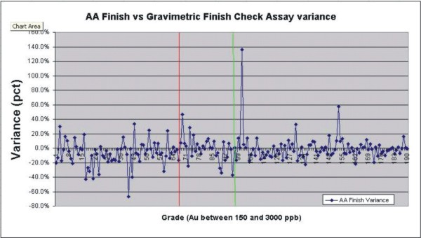
Figure
12-6. Variance of AA-Finish samples < 3000 ppb
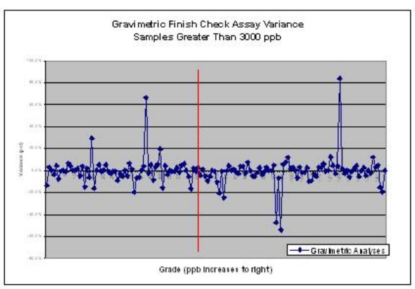
Figure
12-7 Gravimetric Finish Comparisons - -Check Assays to Original
Assays
Although
there were many more samples outside the accepted 10% variance
limit failure
rate, only 14 serious busts were found that required attention
(Table 12-5).
These busts were from 3 check assay jobs, with only one job
(RE04074554)
considered as a bad assay batch, but from the check lab (ALS
Chemex) rather than
the primary, BSi Inspectorate. These 4 samples were re-assayed,
with results
bringing the samples into conformity with acceptable standards.
Table
12-5: Failure Rate for 3 Check Assay Jobs.
|
Job
Number
|
#
samples
|
#
Failures
|
Rate
|
|
RE04074554
|
31
|
4
|
13%
|
|
RE04083801
|
62
|
4
|
6%
|
|
RE05000525
|
47
|
5
|
11%
|
Of
the
remaining ten assays, 4 samples assay below 6000 ppb and can
be attributed to
machine error, the other 5 have values greater than 0.5 oz/ton.
These
higher-grade assays have variances in gravimetric analyses
at less than 20%,
usually between 12 and 15%. Discussions with the laboratories
suggest
differences in equipment, reagents, and methods may account
for the variations.
Variations at this concentration level, in so few samples,
can be accepted
because of the consistency in error between the two labs (the
errors are always
between 12 and 15%).
Due
to
the inconsistency in assay method applied it is difficult to
assess the accuracy
of the laboratories’ analytical procedures for the entire batch of samples. The
simple fact that variance errors are consistently less than
20% for most
comparisons indicates variation due to analytical methods (AA
vs. gravimetric),
rather than procedural errors, can account for the differences.
The errors in
gravimetric comparisons, the only truly correlative analytical
methods that are
available, suggest some tightening of procedures can be achieved
at both labs
(busts at Chemex and low gravimetric analyses at less than
8 ppm at
Inspectorate). Only 14 assays, due to a variety of reasons,
from a set of 254
were found to be of truly poor quality. These represent less
than 10% of the
number of assays used in the statistical studies, and indicate
acceptable levels
of analytical quality for the primary assay values.
12.9 Laboratory
Quality Assurance and Control
Internal
QA/QC samples were provided to Atna Resources Inc. by the assay
lab. Internal
lab protocol consisted of running 1 in 20 to 1 in 40 samples
(depending on job
size) as internal duplicates to check assay adequacy. Results
were posted on the
final certificate under the heading “QA/QC Au ppb”. The duplicate sample was
taken from the coarse reject with the preparation of an entirely
new pulp, and
run as blind samples within the job. Evaluation of the results
looked at the
number of samples falling outside an accepted 10% range. If
less than 90% of the
samples are within the 10% range, then affected assays falling
outside the 10%
range should be re-run.
Evaluation
of the laboratory duplicates compared the original assay to
the blind duplicate.
A total of 460 duplicates were inserted by the lab throughout
the program. To
make meaningful comparisons, though, only those samples greater
than 30 times
detection (above 150 ppb) were used, as variances at lower
levels are extreme
and meaningless. Given these parameters, only 177 samples were
used to evaluate
lab internal QA/QC. Of the 177 samples, 10 (5.6%) fell outside
the accepted 10%
of the original assay (94% of the samples were within the allowable
10% error
range).
Figure
12-8 represents an x-y scatter plot with red lines representing
a 10 percent
error. Two samples with the largest variances were found to
contain data entry
errors. These have been corrected in the database. Other samples
exceeding the
error limits are unexplained, but given only 5.6% of the samples
were bad, the
internal lab duplicates validate assay adequacy and accuracy.
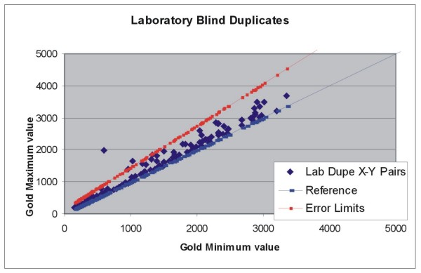
Figure
12-8. Laboratory Blind Duplicates
13.0 Data
Verification
13.1 Summary
Verification
of previous exploration drilling assay results is required
as part of prudent
due-diligence studies for the acquisition and ongoing exploration
of the ▇▇▇▇▇▇
Mine property. The process of data verification follows several
threads. One
thread is retroactive correction and maintenance of the large
▇▇▇▇▇▇ Mining
Company database. A second important thread consists of re-analyzing
existing
drill sample pulps from mineralized intercepts within the CX
and Range Front
target areas. Pulps were taken from the onsite pulp library
maintained by ▇▇▇▇▇▇
Mining Co., which includes all drilling done on the property
while PMC was
operator.
13.2 Database
of Previous Drilling
Barrick
supplied digital data on CD for the ▇▇▇▇▇▇ Mine. Contained
on the CD were two
Microsoft Access databases containing surface sample locations
and geochemistry,
and, most importantly, drill-hole location, assay, geology,
and survey data.
This data set was also duplicated in a Vulcan data set, and
as ASCII text files
used to import/export in Vulcan. After ▇▇▇▇ established a working
office at the
mine site, additional data was found, and it was learned that
Homestake
personnel had put together the entire data set digitally.
HMC
essentially compiled the ▇▇▇▇▇▇ Mine assay database under two
separate efforts.
One was the entry of older ▇▇▇▇▇▇ Mining company data, probably
from a
combination of hand entry and extraction from the MedSystem
database that was
used at the mine. The other was the acquisition of new data
from ongoing HMC
exploration efforts. Data were initially compiled in Excel
spreadsheets before
final storage in an Access database. Homestake’s Access database contained
tables for the following information:
|
1)
|
Collar
information
|
|
2)
|
Downhole
survey information
|
|
3)
|
Geologic
information
|
|
4)
|
Assay
information
|
|
5)
|
Geochemistry
|
|
6)
|
Grade
thickness
|
While
the
database is useable in the structure it was created in, Atna
had additional data
to track, and decided to create a new data structure appropriate
for its own
work, and then import the Homestake data structure into the
new Atna
structure.
Data
acquisition issues forced the datasets into 2 separate Microsoft
Access
databases, one for Atna Resources data and the other for historic
data. Data
management was structured in this manner to allow ongoing cleaning
of historic
data without interfering with introduction of newly acquired
data. These data
sets are being maintained as separate entities until they can
be integrated with
confidence. Both databases have the same table structures,
field names, and
table names, and should be easy to merge.
13.2.1 Tables
In
both
databases, the main data sets are contained in the following
tables:
DH_Collar
- all collar information
DH_Assay
- all gold assay information
DH_Geochem
- all drill-hole trace element geochemistry
DH_RQD
-
RQD data
DH_Survey
- down hole survey data
DH_Geology
- lithology and formation information
DH_Alteration
- alteration data
For
the
Atna Resources database the following tables also apply:
TRANSMITTALS
- lab job certificate numbers (key field for assays and a tracking
device)
DH_SAMPLERS_RECORD_SHEET
- cross reference list of drill-hole footages, sample numbers,
standards, and
blanks. Sample Type is also referenced so as to quickly discriminate
between
core from RC.
CHECKS_STANDARDS
- all check and standard assays for QA/QC
Although
these tables exist in the historic data set there is no information
contained in
them.
13.2.2 Data
Corrections
Prior
to
entering data into the newly created data structure, any errors
were identified
and resolved. The basis for fixing identified errors was the
well-maintained
filing system containing most, if not all, drill logs, downhole
survey data, and
HMC assay data. While ▇▇▇▇▇▇ Mining Company was operator, assaying
was done in
the mine’s own labs, and Atna Resources has yet to locate original drill-hole
assay sheets from that era. Atna's only source for these gold
assays are values
hand-entered onto lithology logs. Consequently, it has been
difficult to check
the validity of some historic data, except as part of Atna’s reassay program
completed on existing pulps from these earlier drilling programs.
The
verification process involved the following steps:
| 1) |
Comparing
collar data to survey, assay, and geology data for
incorrect depths,
Azimuths, and dip values.
|
| 2) |
Check
survey, assay, and geology data for missing and/or
overlapping
intervals
|
| 3) |
Randomly
check drill-hole geologic, survey, and assay data
against logs and
hardcopy data.
|
| 4) |
Plot
sections and check for obvious errors in hole trace
orientations and
potential missing assay data (no data
present).
|
The
following errors were detected and resolved:
Collar
Table
-
Approximately 100 known errors involving incorrect depths,
azimuths, and dip
values have been corrected
Geology
Table
-
Approximately 70 known errors correcting length overruns (survey
depth greater
than TD), overlapping intervals, and missing intervals.
Accuracy
of geologic data is subjective and based on the logger for
lithology and
formation call. Typographical errors in the database are not
known, but probably
occur. Other errors that have not been fixed include multiple
entries (i.e. Flt,
FT, Fault) for the same data type and duplicate entries for
the same interval.
Actual drill logs will be Atna’s definitive source for interpreting
geology.
The
geology table has not actually been loaded into the new data
structure, but
rather resides in its original form as a separate table within
the
database.
Survey
Table
-
Approximately 110 errors including length overruns, missing
intervals, out of
sequence intervals, and bad azimuth or dip values.
Geochem
Table
- All
data has missing intervals. Data has not been fixed yet, and
will be done on
loading when data is needed. Homestake did not run all intervals
from the drill
holes sampled in their geochemistry program, leaving large
gaps in the from and
to sequences within the database.
Assay
Table (DH_Assay)
This
is
the most important table in the database for generating resource
estimates and
must be clean. The original structure of the table contained
the following
fields.
Table
13-1: Field Definitions in (HMC) ▇▇▇▇▇▇ Database
|
FIELD
|
Data
Type
|
|
HOLEID
|
Hole
name identifier
|
|
FROM
|
Beginning
assay interval
|
|
TO
|
End
assay interval
|
|
AUPPB
|
HMC-Chemex
Fire assays in ppb
|
|
AUFA
|
HMC
and ▇▇▇▇▇▇ Fire Assay in oz/ton
|
|
AUCN
|
HMC
cyanide assays and ▇▇▇▇▇▇ ▇▇ cyanide soluble assays
|
|
AUMOZ
|
FACalc
oz/ton multiplied by 1000
|
|
FACALC
|
Ounce
per ton numbers used for modeling, Calculated from
AUPPB or taken from
AUFA fields
|
|
CN_FA
|
Ratio
of CN vs. FA analyses
|
|
CN_FA_T
|
Unknown
|
|
CALC_CN
|
Unknown
|
This
structure was used primarily for pre-Atna resource
modeling
efforts in Vulcan software.
Many
of
the problems and errors encountered in the assay database came
about as a result
of the pulp re-assay program. That program, described below,
caught several
errors, ranging from simple clerical entry errors to the practice
of entering
only single Fire Assay values for the ▇▇▇▇▇▇ Mining Co. data,
regardless of
check assays and any additional assay reporting. Below is a
summary of errors
caught while validating the data.
Incorrect
assays:
-
Several holes (for example, RH-123) have assay values entered
showing grade,
where the only source of information indicates either no grade,
or assay values
in the wrong interval.
Missing
intervals:
-
Approximately 25 holes with intervals actually missing.
Intervals
beyond hole depths:
-
Approximately 60 holes with intervals beyond hole depths, including
many
intervals containing anomalous and low grade gold values.
Overlapping
intervals:
- 35
holes with overlapping intervals.
Typos:
-Several assays have typos caught by the pulp re-assay program.
Many probably
still exist. In one instance the typo changed a 10 ppm assay
to 1
ppm
Other
errors in the assay database that are less egregious include:
"Less
than" detection:
-
Although not significant for ATNA's purposes, since the company
is focused on
high grade values, it leads to a general sense of poor quality
control and
checks on the original database. HMC converted all "less than"
detection values
to "+½" value. This was done for statistical purposes during resource
estimation. Converting less than detection values is not an
issue generally, but
it has been inconsistently applied. All “less than” detection values have been
identified and converted back to reflect original results on
certificates or
drill logs.
Missing
assays:
-
Homestake Mining Company entered "-1" for any assay that was
missing. This
included -1 for any analyses that were not run, and for samples
with missing
intervals due to poor recovery, voids, or fractures. Since
Atna is pursuing a
structural target, it is important to make the distinction.
In the current
database a value of -8 or -9 has been entered to reflect the
distinction. "-8"
values indicate no assay was run, even though a sample was
taken, or if it is
not known why an assay is not present. A "-9" indicates no
assay due to
insufficient sample, or missing sample, attributable to geologic
reasons.
Numerous holes have been fixed but many others have not. These
discoveries
continue as holes are plotted on section.
13.2.3 General
description of pre Atna assay results and procedures.
Because
no assay certificates exist for ▇▇▇▇▇▇ Mining Company drilling,
it cannot be
said with certainty where actual assays were completed, nor
whether the assays
were accurately entered on the log sheets. It has been generally
accepted the
assays were completed at the mine site.
▇▇▇▇▇▇
Mining Company's standard practice was to run assays using
AA methods. For all
assays this was generally done on a cyanide ▇▇▇▇▇, as interest
lay only in
identifying leachable ore. After a certain date (unknown) ▇▇▇▇▇▇
Mining began to
run fire assays with an AA finish on all assays over 0.01 opt,
and selectively
ran check assays at third-party laboratories for numerous high-grade
zones. All
the assay information was hand written on the lithologic log.
▇▇▇▇▇▇
Mining Co detection limits were <0.003 and <0.001 oz/ton, with the
distinction between detection limits being the age of the assay.
These values
were also converted to “+1/2” detection limit values. In addition, 0.0005 and
0.0006 oz/ton were also found in the database for ▇▇▇▇▇▇ Mining
Company Holes.
On the original logs, these assays were reported as “Nil”, <0.003, or as
"<0.001 oz/ton." For ▇▇▇▇▇▇ Mining company holes, all “less than” detection
values have been converted to -0.001 or -0.003 for oz/ton in
the
database.
Validity
for using ▇▇▇▇▇▇ Mining Company data derives from the pulp
re-assay
program.
Homestake
Mining Company assayed all drill holes at ALS Chemex in Reno,
NV. ALS Chemex
provided sample pickup and preparation services. These procedures
are consistent
with standard practices in the industry and include:
|
1)
|
A
primary crush to less than -80 mesh
|
|
2)
|
Split
of 300 grams of material for pulverization to -180
mesh
|
|
3)
|
A
30 gram split for digestion and
assay
|
All
assays were completed using the AUAA23 Fire Assay method. Initial
assay results
were finished using an AA machine with results reported in
ppb values. If
results came back less than 10,000 ppb gold these were reported
on the
certificate using the actual ppb value. Samples that assayed
greater than 10,000
ppb on the initial AA finish, were re-assayed using an assay-grade
gravimetric
finish. These gravimetric assays were reported on the same
certificate using
ounce per ton values in a separate column. The value “>10000” was placed in
the ppb column for any gravimetric analyses.
Detection
limits for gold analyses on ALS Chemex assay certificates are
-5 ppb and -0.0005
for oz/ton. Most HMC holes reporting such values were converted,
for statistical
purposes, to 2.5 ppb and .0003 opt. Several HMC holes also
had actual ppb
results of 34.3, 17.8, 18.9, and 56.0 reported as 2.5 ppb values
in the
database. For HMC holes all "less than" detection values have
been converted
back to -5 and -0.0005, respectively, for ppb and oz/ton in
the
database.
Homestake
also ran, as standard practice, a cyanide shake ▇▇▇▇▇ assay
on any result
greater than 0.01 oz/ton (334 ppb). These were reported on
the certificate under
a column labeled Au CN OPT. Detection limits for the cyanide
assays were less
than 0.001 oz/ton.
Pulps
from HMC’s exploration drilling were also subject to re-assay.
13.3 Pulp
Selection
Atna
Resources re-analyzed 652 pulps from drill-hole samples as
part of a due
diligence effort to confirm the presence of strong gold mineralization
at depth
and along strike from open pits and other hypothesized structures
at the ▇▇▇▇▇▇
Mine. Selection of pulps was based on grade, and whether or
not the mineralized
intercept was contained within either the Range Front or CX
fault zone. Grade
ranges for samples to pull were those intervals above 0.10
oz/ton, unless the
sample was internal to a mineralized intercept. The pulps came
from the mine’s
pulp library stored on site.
Intervals
pulled are listed in Appendix
13-1,
Pulp
Re-Assay List. Care was taken to maintain the order and status
of the library.
All pulps pulled for re-assay were replaced in their original
boxes, in order,
and the boxes restored to their original locations on the mine
site. After
pulling and cataloguing the pulps, Atna staff delivered the
pulps to the BSi
Inspectorate laboratory facility in Reno for re-bagging and
insertion of blind
standards and blanks. ALS Chemex Laboratories completed the
analytical
work.
13.4 Re-Assay
Methods
13.4.1 Processing
by BSi Inspectorate
BSi
Inspectorate re-bagged the pulps using the following process:
| 1) |
In
order to maintain a uniform sample sequence with
the insertion of blind
standards and blanks original pulps must be re-bagged
and
re-numbered.
|
| 2) |
Existing
pulps were rolled and a 100 gram split taken for
the new
assay.
|
3)Pulps
were re-bagged in a new envelope and given a new sample number.
A
cross-reference list was maintained to index the original pulp
sample numbers to
the new split pulp sample numbers. The original list was given
to BSi
Inspectorate as an Excel spreadsheet containing existing pulp
sample numbers and
locations for the insertion of blind standards and blanks.
BSi Inspectorate then
filled in an index field on the list with the new sample number
sequence. The
list was delivered to Atna Resources, both as hard copy and
digital, once pulp
preparation was completed.
4)BSi
Inspectorate inserted certified standards from CDN Resource
Laboratories Ltd.
into the sample sequence at a rate of 1 standard for every
20 samples. Standards
were given sample numbers that maintained a uniform numbering
sequence for the
entire job (see step 1). These numbers were listed on the cross-reference
sheet
with the following additional information: accepted assay value
for the
standard, matrix type, and Standard Reference ID #. Statistics
for the certified
standards were available from CDN Resource Laboratories’ website. Table 13-2,
CDN Resource Laboratories Standards, lists the standards.
5)BSi
Inspectorate also prepared and inserted into the sample sequence
silica sand
blanks at a rate of 1 for every 20 samples. Standards and Blanks
were not
inserted adjacent to each other. Again, sample numbers for
blanks maintained a
uniform numbering sequence for the entire job, and were identified
in the BSi
Inspectorate cross reference list as “silica sand blank” along with a
corresponding sample number.
6)Samples
were delivered to ALS Chemex in four separate batches for analysis.
13.4.2 Processing
by ALS Chemex
Samples
were analyzed by ALS Chemex with these conditions:
| 1) |
New
fusion crucibles.
|
| 2) |
Gold
assays determined by 1 assay-ton, Fire assay
with an AA finish (Au-AA25),
or via a gravimetric finish for samples greater
than 100
ppm.
|
| 3) |
Results
reported directly to Atna
Resources.
|
Atna
compared and contrasted the reproducibility of the gold values
obtained in the
re-analysis project with those originally reported to ▇▇▇▇▇▇
Mining Company. A
statistical analysis of the analytical data, certified gold
standards, and
silica blanks was completed to assist in gauging the reliability
of the
data.
Table
13-2: CDN Resource Laboratory Standards
|
Standard
Name
|
Accepted
Value and Error Range
|
|
CDN-GS-1
|
5.07
± 0.43 g/t Au
|
|
CDN-GS-2
|
1.53
± 0.18 g/t Au
|
|
CDN-GS-3
|
0.79
± 0.07 g/t Au
|
|
CDN-GS-4
|
3.45
± 0.21 g/t Au
|
|
CDN-GS-5
|
20.77
± 0.91 g/t Au
|
|
CDN-GS-6
|
9.99
± 0.50 g/t Au
|
|
CDN-GS-7
|
5.15
± 0.46 g/t Au
|
|
CDN-GS-8
|
33.5
± 1.7 g/t Au
|
|
CDN-GS-9
|
1.75
± 0.14 g/t Au
|
|
CDN-GS-P3
|
0.30
± 0.04 g/t Au
|
|
CDN-GS-10
|
0.82
± 0.09 g/t Au
|
|
CDN-GS-1A
|
0.78
± 0.08 g/t Au
|
|
CDN-GS-13
|
1.80
± 0.18 g/t Au
|
|
CDN-GS-11
|
3.40
± 0.27 g/t Au
|
|
CDN-GS-5A
|
5.10
± 0.27 g/t Au
|
|
CDN-GS-14
|
7.47
± 0.31 g/t Au
|
|
CDN-GS-12
|
9.98
± 0.37 g/t Au
|
|
CDN-GS-15
|
15.31
± 0.58 g/t Au
|
|
CDN-GS-20
|
20.60
± 0.67 g/t Au
|
|
CDN-GS-30
|
33.5
± 1.4 g/t Au
|
13.5 Re-Assay
Results
New
assay
values for the pulp program came back from ALS Chemex in 5
separate jobs. ALS
Chemex split the second pulp batch (491 samples) from Inspectorate
into two
separate jobs (270 and 221 samples) because the number of samples
exceeded
Chemex’s internal QC job size allotment of 300 samples. Results from
those
assays were compiled and statistically analyzed by comparing
the new assay
values to the original values.
Initial
results of that analysis showed a significant decline in gold
concentrations for
numerous samples when compared to original assay results, many
of which were
also done by ALS Chemex Laboratories. The lower gold concentrations
occurred at
all grade levels, but happened to be particularly acute in
samples assaying
above 8 g/t Au. Additional statistical evaluations also showed
20% of the
analyses fell outside of an accepted 10% variance from original
gold results, as
well as uniformly lower results and large variances in values
of standards when
compared to accepted values.
Several
samples were pulled from each assay job for additional testing.
Statistical
analyses of results from the testing, with some exceptions,
fell within accepted
10% variances from original assay results (Figure 13-1). This
is particularly
true of samples above 10 ppm, which, in the initial re-assay
tests fell below
the -10% variance level, and of all standards re-analyzed during
the testing
(Table 13-3). Re-analysis of these samples led to the conclusion
that bad assays
of the newly-submitted pulps were to blame, in particular improper
fluxing of
the sample. Two jobs had to be re-analyzed based on the tests.
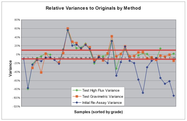
Figure
13-1. Test Result Variances
(Red
lines are 10% acceptable limits).
Table
13-3: Analyses of Standards Used in Testing.
|
Samp_ID
|
New_Au_ppb
|
Accpt_Au_ppb
|
HighFlux_Au_PPM
(method1)
|
Grav_Au_PPM
(Method 2)
|
Error
tolerance +/-
|
Within
Tolerance
|
|
RE04058845-27
|
770
|
780
|
0.75
|
|
+/-
0.140 g/t
|
No
|
|
RE04058845-5
|
4550
|
5150
|
|
|
+/-
0.460 g/t
|
Yes
|
|
RE04054309-14
|
740
|
820
|
|
|
+/-
0.09 g/t
|
Yes
|
|
RE04054309-74
|
9460
|
9990
|
9.65
|
9.59
|
+/-
0.50 g/t
|
Yes
|
|
RE04057300-344
|
4840
|
5150
|
5.12
|
4.73
|
+/-
0.460 g/t
|
Yes
|
|
RE04056499-24
|
16950
|
20770
|
|
20
|
+/-
0.91 g/t
|
Yes
(Gravimetric value)
|
|
RE04056499-44
|
4770
|
5150
|
5.28
|
5.22
|
+/-
0.460 g/t
|
Yes
|
|
RE04056499-104
|
17950
|
20770
|
19.8
|
19.95
|
+/-
0.91 g/t
|
Yes
|
*
Note
sample 27 was initially misreported as to original value (1775
ppb). The value
should be 780 ppb.
High
variations in results between 10 and 25 ppm from several samples
in Figure 13-1
are from samples run by ▇▇▇▇▇▇ Mining Company. These variations
are at odds with
accuracy comparisons with the standards analyzed in the same
batch. Checks of
the original logs traced discrepancies in the data to various
problems,
including database entry errors, variances in original assays,
or poor quality
control on older ▇▇▇▇▇▇ Mining Co. jobs. Use of different pulps
for fire assay
analyses and check samples is also a part of the problem, as
indicated by
several analyses (e.g. RHA 456 460-465) where the Fire assay
value (on a
different pulp) was much less than the original AA assay, and
▇▇▇▇’s re-assays
reflect the AA result. When comparing re-assay results with
▇▇▇▇▇▇ Mining’s
original data there is at least one original assay value that
does correlate
well with the re-assay results, indicating the pulp in the
library came from
this assay rather than the original AA assay. In any event,
these variances were
tracked down and an acceptable reason and solution for the
variance was then
determined.
After
resolution of variance issues, the results were incorporated
into the data set
and re-analyzed statistically. The analyses fell within acceptable
limits on the
second assay set and have been incorporated into the database
as the actual
values for the re-assay effort.
13.6 Discussion
Atna’s
re-assay results substantiate the accuracy of the original
HMC and PMC assay
results, showing the original numbers to be valid. Furthermore,
the re-assay
results also lend a degree of confidence to the ▇▇▇▇▇▇ Mining
Company assay data
as a whole, indicating that the values obtained by ▇▇▇▇▇▇ Mining’s original
assays and the values written on the logs and entered into
the database, can be
used even for those holes not re-assayed under this program.
After
verification and correction of database records, ▇▇▇▇ was able
to enter the data
set into a newly structured Access database. The assay table
was structured to
reflect the true nature of the assay data, with fields for
AA,, gravimetric,
▇▇▇▇▇▇ fire assay data, and Homestake ppb data. A field was
also added to store
the values to be used in resource modeling and estimation.
Since
there are several types and generations of assay data, even
for a particular
sample, the concern with the data set was, Which gold assay
value to use for
resource estimation. Standard geostatistical practice is to
use the original
assay so as to not alter the inherent variability within the
deposit (▇▇▇▇▇
▇▇▇▇▇, personal communication, 2005). An order of precedence
must be used to
ensure that the highest quality assay method, and thus the
highest quality
value, is used from the several generations of available data.
The restructured
Atna database uses this order of precedence:
|
1)
|
Atna
re-assay data for HMC and PMC holes
|
|
2)
|
Fire
assay gravimetric data for HMC and Fire Assay AA
data for PMC
holes.
|
|
3)
|
Fire
assay ppb values for HMC holes converted to OPT using
- oz/t = Au
ppb/34285.7
|
|
4)
|
AA
assays for PMC holes.
|
|
5)
|
Cyanide
assays for all others (purely theoretical, as some
higher-quality
measurement exists for every
sample).
|
This
precedence was applied and the data stored in the Field AuFA_Calc,
and are the
values to be used for all modeling and resource estimation
purposes.
14.0 Database
Audit
14.1 Analytical
Data
A
separate audit of the assay database followed the verification
and cleaning
process described in section 13 above. This audit was of assay
data from an MS
Access database of all drilling completed on the ▇▇▇▇▇▇ Mine
Property to the end
of exploration activities in 2001, and consisted of a mix of
data from ▇▇▇▇▇▇
Mining Company and Homestake Mining Company drilling. Drill
data of material
interest to Atna are considered to be
those
holes intersecting the Range Front or CX fault zones in areas
where identified
gold mineralization has significant potential to be developed
into economic
reserves. A total of 370 holes from the ▇▇▇▇▇▇ Mine Assay database,
identified
through cross-section work, are being used for modeling and
resource estimates
for these two zones.
14.1.1 Validation
Process
Seventy-four
drill holes, representing 20% of the 370 holes of interest
to Atna, were picked
randomly using Microsoft Excel:
|
1.
|
Each
of the 370 holes was given a unique numeric index
number in the Access
database and then exported to
Excel.
|
|
2.
|
Using
the Data Analysis toolpack add-in for Excel,
a random sequence of numbers
was generated using the unique index number as
a
reference.
|
|
3.
|
The
selected index numbers generated by Excel were
imported back into Access
and cross-referenced to drill-hole
ID.
|
|
4.
|
An
assay set was extracted from the database using
the cross-referenced
drill-hole number list. This list was further
winnowed for checking
purposes by examining only assays greater than
or equal to 0.08
oz/ton.
|
|
5.
|
Assay
values from the database were compared to assay
certificates for HMC data,
and against values presented on drill-hole logs
for ▇▇▇▇▇▇ Mining Company
data. (Actual assay certificates have yet to
be found for ▇▇▇▇▇▇ Mining
Company work.)
|
This
procedure generated a total of 7,479 individual assays for
the 74 drill holes.
Extracting values greater than or equal to 0.08 oz/ton yielded
a total of 216
assays to be checked for errors. Appendix
14-1,: Error Analysis of Randomly Selected ▇▇▇▇▇▇ Database
Assays,
lists
the hole numbers and assay intervals used in the check process,
and the errors
found.
Of
the
216 assays checked there were 16 errors, representing 7% of
the total number
checked. Only 7 of the 16 would materially affect the database
(3%). Of the 16
errors, four represent check values entered that were inconsistent
with the use
of the primary assay in the database, 4 errors represent assay
values that could
not be followed up with certificates. An additional three entries
were not made
that affect the value used for resource estimates. There was
one typographic
entry error, one unknown error, and one duplicate entry, which
then caused an
out of sequence error. The above errors have been changed in
the
database.
The
total
number of errors found in the verification and cleaning process
was 475. The
verification process focused on the 370 holes used to calculate
the resource
estimate. A total of 61416 records (combined Collar, Survey,
Geology, and Assay
tables) exist in this subset of data, leading to an overall
error rate of
0.7%.
14.2 Drill-hole
Collar Location
Due
to
degradation by mining activity, reclamation, and other ground
disturbance,
physical location of pre-Atna drill-hole collars is impractical,
if not
impossible, for most ground surrounding the pit areas. However,
▇▇▇▇▇▇ Mining
Company routinely surveyed drill-hole collar locations. This
was done by the
mine surveyor using a total station (▇. ▇▇▇▇▇▇, personal communication,
2004).
Records for each hole were meticulously kept in a log book
listing hole number,
coordinate values, and elevations. This book is kept in the
file system onsite.
All coordinate values were obtained in local mine grid values.
The
mine
grid origin of 10,000N, 10,000E was established on the common
corner of sections
28, 29, 32, and 33 of T48N, R24E, MDBM, now mined out. An Array
of control
points has been established throughout the property for survey
control and has
been well documented. Many of these points are still well marked
and can be used
for future surveys.
Homestake
Mining Company drill holes were also surveyed in. These were
done with GPS units
and a local base station. GPS used was a Trimble LS5000 survey
grade RTK system.
Prior to surveying the holes a transformation from latitude-longitude
values to
local mine grid was established in the GPS data collector using
pre-existing
survey points. Mine grid coordinates were able to be read directly
from the GPS
unit and stored in files. (▇. ▇▇▇▇▇▇, personal communication,
2004)
Prior
to
Atna’s drilling campaign, a survey was completed to see if non-survey-grade
GPS
would temporarily locate collar coordinates for plotting purposes.
The GPS used
was a Trimble AG132 with autonomous precision of 5 meters.
Local grid
coordinates were obtained through ArcPad by using a datum definition
defined for
the ▇▇▇▇▇▇ Grid system. Settings were established in the AG
132 to read
differential GPS fixes from the Coast Guard beacon system if
they were
available. This correction, although not nearly optimum, brought
relative
accuracy of the surveys to within 15 feet, acceptable for initial
plotting.
After system setup, the unit was taken to the field and used
to resurvey control
points and several (15) drill holes (water monitor ▇▇▇▇▇ and
other). Results
from this survey show the GPS unit to be accurate to within
8 feet in the X
direction and 6 feet in the Y direction from any survey point
or known drill
hole.
For
underground mining, the GPS coordinate accuracy is insufficient.
Due to this
fact, a professional surveyor using a total station obtained
Atna drill-hole
collar coordinates. The survey was completed in December, near
the end of
drilling activity and after completion of all drill-hole pre-collars.
The
surveyor used an Atna geologist as ▇▇▇ ▇▇▇ because his knowledge
of the physical
drill-hole collar locations aided in the speed and accuracy
of the survey.
Coordinates and elevations are stored in the drill-hole collar
table of the Atna
database, and shown in Appendix
14-2,
Drill-hole Collar Table.
15.0 Adjacent
Properties
15.1 Summary
The
valley east of the ▇▇▇▇▇▇ Mountains is a discrete unnamed valley
within the
Humboldt River drainage basin, hosting on its west flank a
series significant
gold deposits. From south to north, these are:
| · |
▇▇▇▇▇▇
|
| · |
▇▇▇▇▇▇
(A Zone; B Zone; C Zone; CX Zone, CX West Zone; MAG
Zone; Range Front
Zone)
|
| · |
▇▇▇▇▇▇▇▇
/ Turquoise Ridge complex
|
| · |
Twin
Creeks (an administrative consolidation of the former
Chimney Creek and
Rabbit Creek properties).
|
Deposits
closest to the ▇▇▇▇▇▇ Mountain front (▇▇▇▇▇▇, ▇▇▇▇▇▇ & ▇▇▇▇▇▇▇▇) are
generally considered to be dominated by structural factors
produced by
high-angle faulting, while deposits somewhat distant from the
mountain front
(Turquoise Ridge and Twin Creeks) are credited with mineralization
dominated by
favorable stratigraphy-however structures play an important
role in focusing
these gold systems into the favorable stratigraphy.
15.2 ▇▇▇▇▇▇
Mine
The
▇▇▇▇▇▇ Deposit is located in the low hills east of the ▇▇▇▇▇▇
Mountains and
north of the Humboldt River, in T. 36 N., R. 41 W. (▇▇▇▇▇ and
▇▇▇▇▇▇▇, 1999).
Its discovery in the 1970s was attributed to regional sampling
(▇▇▇▇▇▇▇▇▇▇,
1983) supported by follow-up rotary drilling. Production was
deferred until
1984, when gold prices then supported mining a resource of
1.7 M tons @ 0.062
opt Au (2.1 g/t) (▇▇▇▇▇▇▇▇▇ et al., 2000).
The
locus
of this mineralization is a broad, NE-striking shear zone dipping
shallowly SE,
paralleling bedding. The principal host rocks are isoclinally
folded
carbonaceous and calcareous shales and silty limestones of
the Middle ▇▇▇▇▇▇
Formation. Silicification is the most prevalent form of alteration,
and is
expressed in a range of settings, from narrowly fracture-controlled,
to widely
dispersed in permeable horizons. Fractured settings provided
higher gold grades.
Multistage vein/alteration systems were recognized at ▇▇▇▇▇▇.
15.3. ▇▇▇▇▇▇▇▇/Turquoise
Ridge Mine Complex
15.3.1 History
Historically,
the focus of exploration at ▇▇▇▇▇▇▇▇ was on its oxide potential,
dating from the
first discoveries in 1934 along the ▇▇▇▇▇▇ Mountain front.
The setting for these
discoveries was fracture-controlled mineralization in the ▇▇▇▇▇▇▇▇
Fault, the
major N-S striking, Basin-Range fault. Deeper exploration on
the fault zone
resulted in high-grade discoveries.
Additional
open pit resources were discovered about 3,000 feet east of
the main fault zone,
in an area later named Turquoise Ridge, and this area was mined
out between 1993
and 1995. Some of the deeper development holes for the pit
bottomed in pillow
basalts believed to be unproductive. Geologists suspected that
the already-mined
pits might actually represent leakage above a productive system,
and began a
delineation program in 1994 that resulted in a commitment to
shaft sinking. The
shaft itself traversed a high-grade zone, and became the focus
of early mine
development. By the end of 1998 the production shaft was in
service.
15.3.2 Geologic
Setting
The
▇▇▇▇▇▇▇▇ deposits are sediment hosted, micron-gold deposits
whose grade is
influenced by the convergence of favorable stratigraphy - often
carbonaceous
mudstone and silty shales, or carbonate debris flow sequences
- and both high-
and low-angle structures of varying orientations.
The
usual
formations mineralized are the Cambrian ▇▇▇▇▇▇, Ordovician
Comus, and Ordovician
Valmy. The ▇▇▇▇▇▇ is part of the eastern platform sequence,
and overlain by
Cambro-Ordovician platform rocks, which include Comus carbonates.
Further west,
the Ordovician Comus includes both calcareous and argillaceous
sediments, and
interbedded mafic volcanics and tuffs. Still further west,
the Ordovician
Valmy(?) is represented by a more siliceous, cherty or volcanic
assemblage,
which is usually interpreted to be in east-directed overthrust
contact with
Comus beneath it. Locally, a depositional contact between Comus
and Valmy is
sometimes inferred. The lower Paleozoic section is usually
in unconformable or
high-angle fault contact with overlying Pennsylvania-Permian
▇▇▇▇▇▇▇ limestone,
and the entire area was covered at one time by unconformable
sheets of Miocene
volcanics, now only preserved in isolated pockets.
Unraveling
the true geologic relationships is significantly complicated
by the overprinting
effects of 4 discrete structural events:
| · |
The
Devono-Mississippian Antler orogeny, which thrust
western-facies siliceous
rocks over eastern-facies
carbonates;
|
| · |
The
Permo-Triassic Sonoma orogeny which reactivated
thrusting
|
| · |
The
Jurassic-Cretaceous ▇▇▇▇▇▇ Orogeny resulting from
Pacific Plate collision
North American plate;
|
| · |
The
mid-Tertiary inception of regional extensional
faulting.
|
15.3.3 Gold
geology
Gold
is
mined underground at Placer Dome’s ▇▇▇▇▇▇▇▇ Mine from two principal ore bodies;
the 194 ore body at the ▇▇▇▇▇▇▇▇ underground operations, and
the Turquoise Ridge
ore body, accessed by the Turquoise Ridge Shaft. Both ore bodies
are localized
at the intersections of NNS striking faults with NE striking
fault
zones.
▇▇▇▇▇▇▇▇
geologists have separated the local stratigraphic section into
4 units, from top
to bottom (▇▇▇▇▇▇▇, 2004):
Unit
1:
siliceous shale and greenstone;
Unit
2: a
debris flow package consisting of limestone clasts in a shale
and micrite
matrix;
Unit
3:
primarily planar-laminated calcareous siltstones and shales
with limestone
interbeds;
Unit
4:
dominantly black mudstone and micrite.
▇▇▇▇▇▇▇▇
Underground mineralization is confined to the fault plane of
the ▇▇▇▇▇▇▇▇ Fault,
and to calcareous/carbonaceous rocks lying within 1,000 feet
of the fault. The
▇▇▇▇▇▇▇▇ fault is a N-S striking 45-55 degree, east-dipping
structure with
several thousand feet of offset, and the 194 orebody lies in
the footwall of the
▇▇▇▇▇▇▇▇ Fault, hosted in units 3 and 4.
Turquoise
Ridge mineralization lies several thousand feet east, in the
hanging wall of the
▇▇▇▇▇▇▇▇ Fault. Gold is preferentially found in horizons of
carbonate debris,
hosted by units 2 and 3. These units appear to be packages
of debris-flow
material that slumped from a carbonate platform into deeper
water. The packages
are volumetrically significant - the horizontal and vertical
dimensions are
measured in thousands of feet - and fed by a variety of faults.
Both
ore
bodies contain a series of dike and sill like intrusions that
occur within the
major fault zones. These are primarily dacite (?) in composition,
but are
thoroughly altered. A major difference between the 194 and
Turquoise Ridge ore
bodies is the presence of calc-silicate alteration at the 194
ore body; due in
large part to the proximity of the Cretaceous ▇▇▇▇▇▇ Granodiorite.
Ground
conditions at the two sites differ considerably. Calc silicate
alteration and
hornfels, produced by the ▇▇▇▇▇▇ stock, produced a much more
competent rock at
▇▇▇▇▇▇▇▇, creating more localized fracture sets and brecciation
in the host
rock. This is evident in the presence of consistent bedding
planes and sharp
fault contacts with minimal brecciation. Rock bolts, steel
sets, and steel mesh
are the primary control for rock stability. Shotcrete is rarely
used (<10% of
drifting) in the drifts at the 194 workings.
In
contrast, at Turquoise Ridge all rocks are extremely broken
up and shattered,
then completely argillized such that no competency exists in
the host rocks at
all. Underground workings are held together through bolting,
mesh, and
shotcrete. ▇▇▇▇▇▇▇▇ geologists attribute the poor competency
to a much stronger
hydrothermal system at Turquoise Ridge than at ▇▇▇▇▇▇▇▇; however,
the structural
ground preparation and distance from the stock may be important
factors as well.
Turquoise Ridge is located at the intersection of NS faults
parallel to the
▇▇▇▇▇▇▇▇ Fault Zone and a large ENE trending fault zone extending
up to Newmont
Gold’s Twin Creeks Mine. These intersecting zones have produced
a large area of
disruption where original bedding has been destroyed by brecciation,
or so badly
fractured that it has no mechanical competency. The hydrothermal
system then
turned the rocks into clays, further destroying mechanical
properties of the
rock package.
15.4 Twin
Creeks
15.4.1 Physiography
The
Twin
Creeks property lies in an alluviated valley southeast of the
Dry Hills, a
northeastern outlier of the ▇▇▇▇▇▇ Range in northern Humboldt
County, Nevada.
The Dry Hills is an area of gently north-dipping Upper Paleozoic
carbonate
sediments, stratigraphically higher than rocks in the rest
of the ▇▇▇▇▇▇ Range,
which consists mainly of Lower Paleozoic clastic sediments
intruded by a large
Cretaceous pluton, which forms the backbone of the Range.
Topography
descends to the south and east from a high point in the Dry
Hills (northwest of
Twin Creeks), with a typical gradient of 100 feet per mile.
A blanket of
matrix-supported alluvium also originates to the northwest,
and thickens
southeastward more rapidly than the regional topographic slope,
reaching
thicknesses of over 700 feet three miles to the south.
15.4.2 Stratigraphy
Besides
the alluvial cover, the rock sequence at Twin Creeks consists
of four main
elements (MacKerrow et al., 1997):
| · |
A
group of Penn-Permian ▇▇▇▇▇▇▇ Formation mixed carbonate
lithologies in
depositional contact with:
|
| · |
A
tectonic unit (Leviathan Thrust Sheet) of possible
Devono-Mississippian
age, thrust eastward over:
|
| · |
A
tightly folded presumed Upper Ordovician group of
predominantly basaltic
▇▇▇▇▇ and flows (with minor interbedded shales and
tuffs),
and:
|
| · |
An
equally tightly folded presumed Lower Ordovician
group of predominantly
shaley rocks (with minor mafic and basaltic igneous
rocks).
|
The
Penn-Permian ▇▇▇▇▇▇▇ Formation was divided functionally into
three Members, and
is the principal host in Vista Pit, with occasional extensions
into northern
Mega Pit. The formation is a transgressive sequence, showing
a basal Lower
Member of siliciclastic-dominated carbonate, a medial Middle
Member dominated by
massive biomicritic limestones and dolomites, and an Upper
Member composed of
siliciclastic sand-and-siltstones.
The
Devono-Mississippian Leviathan Thrust Sheet consists of an
informal Upper Member
comprised mostly of exceptionally thick sequences of pillow
basalts, and an
informal Lower Member dominated by interbedded greenstones,
cherts & tuffs.
The Lower Member of the sheet crops out along the west wall
of Mega Pit, where
it dips about 20 degrees to the west, and sporadically appears
as an
east-dipping remnant along the northeast wall, suggesting that
the Leviathan
Thrust surface defined a north-trending antiform now cored
by Mega
Pit.
The
Ordovician package is coherently folded into an overturned,
eastward-verging Z.
This package consists of three elements: a generally flat-lying,
mildly arched
and warped Upper Limb on the west side of Section 19 known
as the Conelea
Anticline, an overturned Middle Limb with no name, and a mildly
arched upright
Lower Limb on the east side of Section 19 known as the Tapper
Anticline.
15.4.3 Structure
The
axial
trace of the Z-fold strikes north-northwest, and the fold plunges
gently NNW at
about 20 degrees. Because of the interplay of this gentle northward
plunge with
the regional southward slope of the bedrock surface, the practical
result is
that, sub-horizontal beds of the Upper Limb of the Z-fold crop
out immediately
beneath alluvium throughout North Mega Pit and on the western
side of South Mega
Pit, while the Upper Limb has been removed by erosion in the
south-central part
of Mega Pit, allowing the steeply dipping beds of the Middle
Limb to subcrop
directly beneath allluvium. Rocks of the third, Lower Limb
either subcrop east
of Mega Pit proper, or lie at depths of decreasing economic
interest (South and
North Mega Pit, respectively).
Given
the
size of the altered and mineralized area and the complexity
of the folding, not
many significant high angle faults have been recognized. The
most important,
from the standpoint of structural understanding, are, from
oldest to
youngest:
| · |
A
district-scale Mega Pit thrust (Ear Thrust) following
the Upper Axial
Plane of the Z-fold in South Mega Pit, with relatively
little measurable
displacement.
|
| · |
A
district-scale Mega Pit thrust (DZ Fault) cutting
obliquely across the
axial planes of the Z-fold, from the Upper Axial
Plane in Mid-Mega Pit to
Lower in North Mega Pit, with perhaps several thousand
feet of
stratigraphic throw.
|
| · |
A
regional NE-trending, high angle, wide sheared zone
in North Mega Pit (TC
Fault) with nominal right-lateral (+/- 400') and
little (50')
down-to-the-north movement.
|
| · |
A
family of NE-trending, high-angle faults with negligible
right-lateral
movement in South Mega Pit (Wry-Tail, Bill’s, and #601
Fault).
|
| · |
A
long, N-S, high-angle, down-to-the-east east-dipping
Mega Pit fault (CP)
with differential bedrock and alluvial displacements
(100 feet and 50
feet, respectively);
|
| · |
A
district-scale, east-directed overthrust
(Leviathan);
|
| · |
A
long, N-S high-angle, down-to-the east east-dipping
fault (20,000)
bordering the Vista Pit area with at least 1,000
feet of
displacement
|
As
far as
is known, most of the faults in Mega Pit can be shown to be
pre-mineral in that
they limit or compartmentalize (hydrothermal) fluid flow within
the mineralized
system. More often than not, only the hangingwalls of low-angle
faults are
mineralized, while the footwalls of high-angle faults are
mineralized.
15.4.4 Erosion
& Alluviation
A
strongly aligned (NNW-SSE), incised erosional channel evolved
along the Mega Pit
corridor, on top of the originally-exposed bedrock surface,
beginning somewhere
in mid-Mega Pit. The erosion which centered on this drainage
axis was driven in
part by the extensive regional N-S alteration present in both
the Upper and
Lower Limb Ordovician rocks (fabrics permitting easy erosion),
and the specific
geometry of upturned altered Middle Limb beds, which promoted
easy channel
incision. This early incision eroded headward (northward) along
strike, through
the rest of the Middle Limb sediments, into the relatively
flat beds of the
Upper Limb at the northern part of Mega Pit. This channel thalweg
became the
depositional center of a thick column of alluvial fill, which
acted as a giant
reservoir of oxygenated ground water, allowing even deeper
oxidation to develop.
The practical result is that a large amount of Mega Pit ore
was economic from
the first deep excavations because the oxidation had materially
lowered the
required economic grade cutoffs, and allowed extraction of
mineralized material
that never would have been economic as sulfide ore.
15.4.5 Mineralization
Mineralization
in Mega Pit occurs in several environments, including fracture
fillings in what
are likely feeder zones; as passive disseminations in permeable
beds bounded by
mafic ▇▇▇▇▇; and as massive replacements in structurally incompetent
fold
hinges. The mineral suite consists principally of auriferous
pyrite,
supplemented by ▇▇▇▇▇▇▇▇ pyrite, orpiment, stibnite, and rare
realgar.
The
fracture fillings require brecciation and a permeable matrix.
The passive
disseminations depend on prior decalcification of the sedimentary
rock within
the igneous 'sandwich'. The massive fold-hinge replacements
depend primarily on
pre-existing silicification, which can be shattered upon folding.
In
spite
of the variety of ore environments, the hydrothermal system
is quite linear, and
confined to a N-S corridor centered on the midline of Sections
6, 7, 18, 19
& 30. Along this corridor, it is clear that the mineralizing
system is
opportunistically exploiting all potential hosts along its
longitudinal path,
and. transgressing north-dipping stratigraphy from south to
north, within a
fairly restricted vertical interval, so that the principal
hosts migrate
upsection as follows:
Section
30: Middle Limb of Z-fold in Ordovician rocks
Section
19: Middle & Upper Limbs of Z-fold in Ordovician rocks
Section
18: Upper Limb of Z-fold in Ordovician rocks, & Leviathan
Section
7: Leviathan and Lower Member of the ▇▇▇▇▇▇▇
Section
6: Lower & Middle Member of the ▇▇▇▇▇▇▇
15.4.6 Alteration
There
are
seven recognizable types of alteration present at Twin Creeks.
In apparent
chronological order, from oldest to youngest, they are:
| · |
silicification
I (Mega Pit)
|
| · |
propylitization
(Mega Pit and Vista Pit)
|
| · |
pyritization
(Mega Pit)
|
| · |
decalcification
(Mega Pit and Vista Pit)
|
| · |
argillization
(Mega Pit and Vista Pit)
|
| · |
silicification
II (Vista Pit)
|
| · |
oxidation
(Mega Pit and Vista Pit)
|
Silicification
I appears to be early, and related almost entirely to the emplacement
of the
Ordovician ▇▇▇▇▇. This is based on the cross-sectional observation
that nearly
all ▇▇▇▇▇ of any consequence are rimmed by an envelope of silicification
(or
extended by a layer of silicification); the envelope itself
is displaced from
the contact by about 3'-7'. The intervening space, between
the sill and the
silica envelope, is pristine because the ▇▇▇▇▇ routinely do
not hornfels their
sedimentary contacts.
Leviathan
Formation is universally propylitized through both pit areas.
The usual
characteristics are pervasive chloritic green color, calcite
veining, and minor
epidote.
The
role
and importance of pyritization at Mega Pit is indeterminate.
A basic assumption
is that much pyrite has been either added to, or remobilized
within, the rocks.
Black shales show a much higher concentration of finely disseminated
pyrite than
would be expected from such organically-poor rocks. Likewise,
mafic phases in
the basalts are often supplemented with euhedral pyrite, either
as
disseminations in the matrix, or as networks of hairline fractures.
The role of
this pyrite as a gold-enhancing agent is uncertain.
Decalcification
is routinely observed in altered rock sequences whose precursors
were
calcareous. Effects range from slight reduction in reaction
to acid to karsts
and solution breccias. The decalcification has made the calcareous
clastics
particularly receptive to gold mineralization.
Argillization
refers especially to the alteration-related development of
clay fabrics,
especially in the contacts of ▇▇▇▇▇. This appears to result
from
pyrite-generated sulfuric acid acting on the feldspars contained
in the ▇▇▇▇▇.
However, thinner basalts in particularly well-mineralized areas
have been
completely penetrated by hydrothermal fluid, allowing an extensive
amount of
sulfuric acid to evolve and decimate the matrix of the basalt
itself.
Various
styles of silicification II are recognized in the Vista Pit
area. Some are
associated with base-metal veins related to the ▇▇▇▇▇▇ stock;
some are
strata-bound occurrences of jasperoid in the hanging-wall of
the Leviathan
thrust complex; and some are stockworks in greenstones.
The
Leviathan thrust surface seems to control the redox boundaries
throughout the
mine area. In Vista Pit, the contact of ▇▇▇▇▇▇▇ Formation with
Upper Leviathan
defines the regional redox surface. In Mega Pit, the oxidation
profile also
follows the sole of the Leviathan Thrust across most of section
19, except in
the vicinity of the central Middle Limb area, where the redox
surface dives
deeply in each of the steeply dipping shale beds between basalt
▇▇▇▇▇. In
general, the redox surface in the horizontally-bedded areas
lies at 350 feet
below surface, diving to up to 1,700 feet in the overturned
beds.
15.4.7 Summary
Twin
Creeks is a package of intercalated impermeable basalt and
permeable, mildly
calcareous clastic sediments. Although the stratigraphic section
dips gently
north, and is folded into an overturned chevron fold, the hydrologic
connectedness of the entire package allows a subhorizontal
corridor of
hydrothermal water access to all the permeable horizons, decalcifying
the
calcareous members and mineralizing them by replacement of
the dissolved fabric.
The corridor is surrounded to the west, east and below by a
prominent front of
remobilized calcite; the front above the corridor is absent
by erosion. The
widespread silicification is pre-mineral, and is only a contact
metamorphic
effect of the Ordovician intrusion of the basaltic ▇▇▇▇▇, and
is therefore not
useful for exploration.
The
root
zone or feeder for this system was a vertical, N-S fracture
zone occurring deep
in, and at the south end of, known economic mineralization,
and its existence
was not suspected until after years of drilling and mining.
Individual
high-grade accumulations occur along a rigid, N-S alignment
with no visible
fracture expression.
The
economic value of Twin Creeks arises because the corridor of
altered rock lies
in a downfaulted block in an extension terrain. The vertical
extent of
alteration allowed deep erosion, and deposition of a thick
cap of alluvium over
the buried deposit. Highly oxygenated water in the alluvial
cap promoted deep
oxidation of the bedrock, converting marginal gold sulfide
grades to economic
oxide grades.
16.0 Mineral
Processing and Metallurgical Testing
This
technical report is in support of a resource calculation only.
While it is
anticipated that the project’s mineralized material will have metallurgical and
mineral processing characteristics similar to those at the
adjacent, producing
mine properties of ▇▇▇▇▇▇▇▇ and Twin Creeks, no detailed metallurgical
studies
have been completed by Atna Resources on the resource zones
summarized in this
technical report.
17.0 Mineral
Resources Estimates
17.1 Introduction
The
mineral resource estimates for the CX and Range Front zones
were made from
3-dimensional block models generated using commercial mine
planning software
(MineSight).
The
project limits are based on a local ▇▇▇▇▇▇ mine grid system
initially developed
during mine operations some years back The mine grid is not
rotated and the
origin (point 10000,10000) is located at 478294.7E,
4553517.9N
in the
UTM Zone 11, North American Datum of 1927 coordinate system.
The mineralized
zones occur roughly between 8500E to 11000E, 9500N to 13500N
and 2500 ft to 5500
ft elevation. The project limits are described in more detail
in section
17.9.
A
series
of vertical cross sections, oriented approximately perpendicular
to the general
trend of the mineralized zones, are utilized for viewing the
deposits in cross
section. This series of 40 sections, numbered 5300NE through
9300NE, are
oriented at an azimuth of 120 degrees and are spaced at 100
ft intervals as
shown in Figure 17-1.
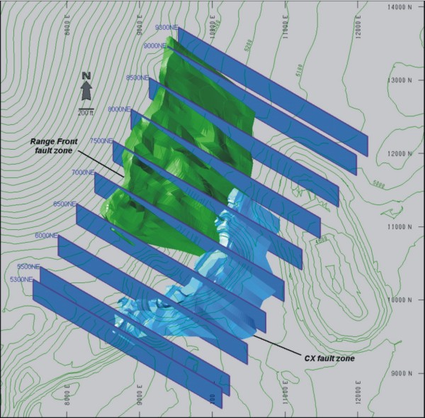
Figure
17-1: Rotated Vertical NW-SE Cross-Sections
The
mineral resource estimate was generated from drill-hole sample
assay results and
a geologic model which relates to the spatial distribution
of gold. Individual
domains, reflecting distinct zones or types of mineralization,
have been defined
and interpolation characteristics have been defined for each
domain based on the
geology, drill-hole spacing and geostatistical analysis of
the data. The degree
of confidence in the resources have been classified based on
the proximity to
sample locations and/or surface exposures and are reported,
as required by NI
43-101, according to the CIM standards on Mineral Resources
and
Reserves.
This
report includes estimates for mineral resources. There are
no mineral reserves
prepared or reported in this Technical Report.
17.2 Geologic
Model, Domains and Coding
17.2.1 Geologic
Model
The
CX
and Range Front are two sub-parallel fault zones which are
separated by
approximately 600 feet and dip to the southeast at about 55
degrees. These fault
zones range in thickness from 30 to over 300 feet and average
approximately 150
feet. The majority of the fault is relatively barren of mineralization;
however,
it does host a distinct, somewhat dendritic web or zone that
is highly enriched
in gold. The nature and distribution of the mineralization
is thought to result
from solutions which passed through the “path(s) of least resistance” depositing
microscopic gold in the receptive host.
Grade
estimations conducted without a distinct internal HG domain
boundary would
result in the averaging of high and low grade samples throughout
the fault zone
resulting in a large but low-grade model. This contradicts
the nature and
distribution of the gold seen in both open pit exposures and
in the drill
holes.
The
enriched, or high-grade (HG), portion of the fault zone is
often defined by the
presence of silica (veins), pyrite, or the visual identification
of traces of
orpiment, realgar, stibnite and/or cinnabar. Unfortunately,
the various vintages
of drilling on the property has resulted in a database which,
in areas, lacks
the details such as the identification of these trace minerals.
As a result, it
is difficult to produce a geologic model of the HG portion
of the fault zone
based on the available geological information.
Therefore,
in order to reproduce the natural distribution of the mineralization
within the
fault zones, a separate HG zone domain has been developed through
a combination
of geostatistical applications and geologic interpretation
of the sample data.
This approach has resulted in a grade model which closely reflects
the trends
observed in the surface exposures and the drilling results.
17.2.2 Domains
and Coding
The
geologic model for the ▇▇▇▇▇▇ gold-bearing zones has been developed
in two
stages. Initially, the CX and Range Front fault zones have
been developed based
on the geologic logging information. Second, the high-grade
portions within the
fault zones are defined through a combination of geostatistical
and manual
methods.
The
CX
and Range Front fault zones have been identified in drill holes
based on
information defined in the drill logs. This process included
a review of core
photos (where available) and re-logging of stored core/cuttings
from historic
drill holes where required.
The
fault
zone intervals were displayed along the drill-hole traces and
the subsequent
geologic interpretation based on this data was conducted on
cross sections. The
interpreted sectional polylines were then linked to produce
3-dimensional
wireframe solids. The CX and Range Front fault zones are shown
in cross section
in Figure 17-2 and in an isometric view in Figure 17-3.
It
should
be noted that geologic model has been extended above the current
surface
topography in the area of the CX pit. The information gained
from including the
mined-out portion of this zone enhances the estimation of the
remaining CX
resource. The final contained resource in this zone is limited
to the current
topographic surface.
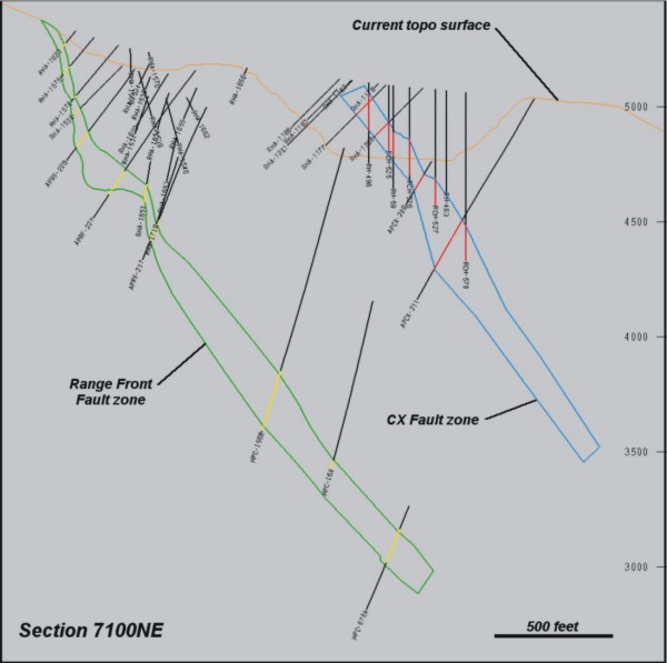
Figure
17-2: Cross Sectional View of CX and Range Front Fault Zones
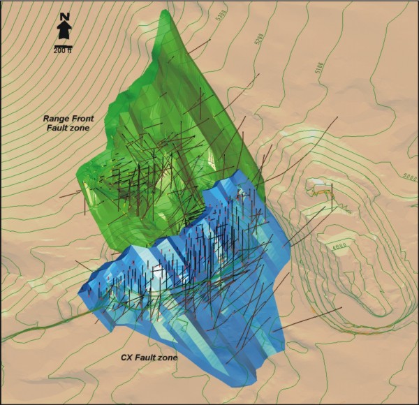
Figure
17-3: Isometric View of CX and Range Front Fault Zones
Following
the generation of the fault zones, the high-grade gold-bearing
domains (HG zone)
were defined as follows. The drill-hole samples were composited
to standard
5-foot sample lengths (this step is described in more detail
in section 17.4).
Samples contained within the fault zones were evaluated both
visually and
statistically (described in detail in section 17.5) and an
indicator threshold
of 0.1 opt Au was selected to define the HG portion of the
fault zone. Samples
within each of the faults were assigned a value of zero (0)
if the grades were
below 0.1 opt Au and a value of one (1) if the grade was above
0.1 opt Au.
Probability estimations were then conducted defining the likelihood
of the
presence of the HG zone located within the fault zone boundaries.
The indicator
probabilities within blocks are estimated using an inverse
distance weighting
(IDW) technique with search directions controlled by “relative elevations” as
described below.
Although
the CX and Range Front fault zones occur as relatively planar
structures, local
undulations exist as shown in figures 17-2 and 17-3. Based
on drilling data and
surface exposures, the HG zones located within the host fault
zones show
undulations and local branching, or bifurcation, into multiple
zones. The
indicator probability estimates using regular ellipse-oriented
IDW or ordinary
kriging (OK) methods resulted in very planar distributions
which are not
representative of the true nature of the HG zones. The “relative elevation” (RE)
approach assigns temporary elevation values to both drill-hole
composites and
the model blocks, relative to the location with respect to
a 3-D surface. Then,
during the resulting estimation, the search orientation is
controlled by the
shape of the designated surface. Note that similar results
could be achieved by
splitting the deposit into a number of individual domains,
each with a unique
search ellipse or set of variogram parameters. However, this
would be a
difficult and potentially inaccurate approach due to the relative
lack of sample
data over some portions of the deposit.
The
controlling surfaces for the RE estimation were initially interpreted
on cross
sections defining the general trend of the HG sample intervals
with respect to
the overall shape of the host fault zones (Figure 17-4). The
interpreted lines
were joined to form 3D surfaces, one for the CX zone and one
for the Range Front
zone. The relative elevations with respect to these surfaces
were then assigned
to the composite samples and model blocks and the indicator
probabilities were
estimated for each of the two zones. Figure 17-5 shows a comparison
of the
indicator probability distributions resulting from the relative
elevation method
versus a regular ellipse oriented IDW estimate (note that the
probability
distribution resulting from an OK application produces very
similar results to
the regular ellipse oriented IDW estimate). Figure 17-6 shows
a similar
comparison, in cross section, from the Range Front zone.
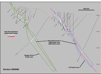
Figure
17-4: Sectional View of HG Zone Trends Within Fault Zones
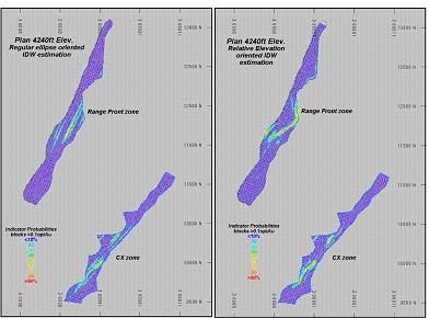
Figure
17-5: Comparison of Indicator Probability Estimation Techniques
-
Plan
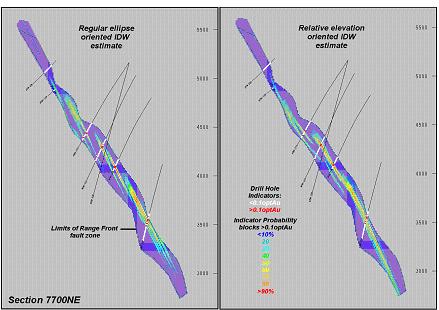
Figure
17-6: Comparison of Indicator Probability Estimation Techniques
-
Section
A
series
of probability grade shells were produced from the block indicator
probability
estimates. A “grade shell” is essentially a 3-dimensional contoured surface
which envelops volumes at defined threshold limits. Probability
grade shells
were produced from 25% to 50% probability limits at 5% increments.
The
probability shells were then compared to the original gold
assay data on section
and plan. In general, the probability shells performed well
in areas with
relatively high sample density. However, in areas where the
drill-hole spacing
increases (typically at depth) or where the HG zone became
quite narrow, the
probability shells did not consistently represent the continuity
of the zone.
Ultimately, the 30% probability shell for the CX zone and the
35% shell for the
Range Front zone were selected as the best fit with the sample
data.
Some
minor modifications were made to the probability shells as
follows. The lower
portion of the CX zone shell, which is not bounded by additional
drilling, was
limited to a distance of 170 feet from a drill hole (Figure
17-7). Also, a thin
zone on the north part of the shell was manually added to more
accurately
represent the continuity encountered in the drilling in this
area.
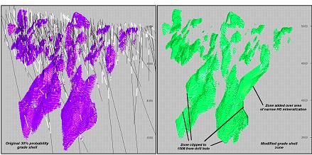
Figure
17-7: CX High-Grade Zone Modifications
Several
additions were made to the Range Front probability grade shell
in areas where
the indicator approach was not able to reproduce the continuity
of the narrow
portions of the deposit. These are shown in Figure 17-7. As
in the CX zone, the
lateral extent of the grade shell in mineralized areas not
bounded by additional
drilling, was limited to a distance of 150 feet from a drill
hole.
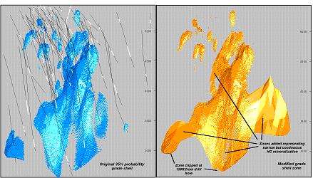
Figure
17-8: Range Front HG Zone Modifications
The
geologic domains are summarized in Table
17-1.
Table
17-1: Summary of Geologic Domains
|
Domain
|
Code#
|
Description
|
|
CX
Fault
|
ZONE=1
|
CX
Fault zone
|
|
RF
Fault
|
ZONE=2
|
Range
Front Fault zone
|
|
CX
HG Zone
|
HGZNE=1
|
Portion
of CX fault >0.1 opt Au
|
|
CX
LG Zone
|
HGZNE=2
|
Portion
of CX fault <0.1 opt Au
|
|
RF
HG Zone
|
HGZNE=3
|
Portion
of Range Front fault >0.1 opt Au
|
|
RF
HG Zone
|
HGZNE=4
|
Portion
of Range Front fault <0.1 opt Au
|
17.3 Available
Data
The
exploration and production history on the ▇▇▇▇▇▇ property dates
back over more
than 50 years and as a result, there is a rather extensive
drill-hole database
consisting of almost 3000 holes. The resource estimate described
in this report
is based on the information provided from a total of 401 drill
holes which are
in close enough proximity to the CX and Range Front zones to
have an influence
on the resource modeling.
Atna
Resources drilled a total of 31 holes during its 2004/05 program.
As of the data
freeze date for this resource estimate (February 15, 2005),
the assay results
from holes APRF-229A and APRF-230 have not been received, however,
the geology
logging information was utilized in the development of the
Range Front fault
zone domain.
The
total
length of drilling in the 401 holes is 236,219 feet, of which
52 holes are
diamond drill (DD) cored holes and the remaining 349 are reverse
circulation
(RC) holes. Note that in an effort to reduce costs, many of
the recent Atna
holes were pre-collared and cased using a reverse circulation
drill rig with a
conversion to DD prior to intersecting the target fault zone.
Although RC
drilling comprises approximately 85% of the holes in the database,
the majority
of this type of drilling is limited to the shallow upper-portion
of the deposits
as shown in Figures 17-9 and 17-10. As a result, the diamond
drilling results
contribute more in relation to the overall resource estimation.
It is estimated
that DD holes cover approximately 65% of the lateral extent
of the CX zone and
approximately 85% of the area of the Range Front zone.
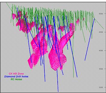
Figure
17-9: Distribution of Drill Holes by Type - CX Zone
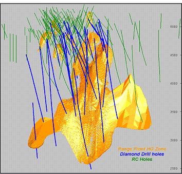
Figure
17-10: Distribution of Drill Holes by Type - Range Front Zone
Samples
in the database which were analyzed but returned values below
the detection
limit were assigned values equal to one half the detection
limit.
There
are
a total of 45,121 samples analyzed for gold in the database.
The majority (89%)
of the sample intervals are a standard length of 5 feet; however
they range from
a minimum of 0.2 feet to a maximum of 82 feet. These large
intervals are
composite samples collected from primarily rotary holes in
areas where gold
mineralization is not anticipated.
The
presence and location of the CX and Range Front fault zones
has been identified
from drill log data, core photos or re-logging of stored core,
in a total of 209
holes in the database. The fault domains have been developed
from the
information provided by these drill holes. The remaining 192
holes in the
database intersect one of the fault zones but the actual location
of the fault
in the hole cannot be confirmed (i.e. It is not clearly identified
in the drill
logs, there are no photos of the core and there is no material
stored from these
holes).
17.4 Compositing
Compositing
of drill-hole samples is performed in order to standardize
the database for
further statistical evaluation. This step eliminates any bias
related to the
sample length that may exist in the data.
As
stated
previously, the vast majority (89%) of the original sample
intervals are 5 feet
in length. As a result of this fact, the composite length was
also selected at 5
feet. The reason for this is that the underlying nature of
the data is retained
in the composited data, where the selection of a longer composite
length
introduces some smoothing, which may mask some of the natural
features of the
data.
Drill-hole
composites are length-weighted and have been generated “down-the-hole” meaning
that composites begin at the top of each hole and are generated
at 5-foot
intervals down the length of the hole.
Prior
to
compositing, the original drill-hole samples were “speared” with the fault ZONE
domain solids. This step tags each sample interval with the
appropriate
ZONE-code designation (ZONE=1 for the CX fault and ZONE=2 for
the Range Front
fault zone). These contacts are then honored during compositing
(i.e. composites
begin and end at the ZONE domain boundaries).
Several
holes were randomly selected and the composited values were
checked for
accuracy. No errors were found.
17.5 Exploratory
Data Analysis
Exploratory
data analysis (EDA) involves the statistical evaluation of
the database in order
to quantify the characteristics of the data. One of the main
purposes of this
exercise is to determine if there is evidence of spatial bias
which may require
the separation and isolation of domains during interpolation.
The application of
separate domains prevents unwanted mixing of data during interpolation
and the
resulting grade model will better reflect the unique properties
of the deposit.
However, use of domain boundaries in areas where the data is
not statistically
unique may impose a bias in the distribution of grades in the
model.
A
domain
boundary, which segregates the data during interpolation, is
typically applied
if the average grade in one domain is significantly different
from that of
another domain. A boundary may also be applied where there
is evidence that
there is a significant change in the grade distribution across
the
contact.
The
various domains that reflect differing styles and distribution
of gold
mineralization in the deposit are listed in Table 17-1. The
drill-hole
composites have been speared with these domains prior to statistical
analysis.
EDA evaluation of these domains includes basic statistics,
contact profiles,
histograms and log-probability plots.
17.5.1 Basic
Statistics by Domain
The
basis
statistics of samples contained within the CX and Range Front
fault zones are
summarized in Table 17-2.
Table
17-2: Drill-hole Sample Statistics by Fault Zone
|
Gold
(opt)
|
CX
Fault
|
Range
Front Fault
|
|
Total
#/ft samples
|
6,750/33,661
|
2,665/13,269
|
|
Min
|
0.0001
|
0.0001
|
|
Max
|
1.840
|
2.337
|
|
Mean
|
0.030
|
0.037
|
|
Std
Dev
|
0.095
|
0.122
|
(Statistics
based on 5-foot drill-hole composite samples, weighted by sample
length)
Table
17-3: Drill-hole Sample Statistics by HG/LG Portion of Fault
Zone
|
Gold
(opt)
|
CX
HG Zone
|
CX
LG Zone
|
RF
HG Zone
|
RF
LG Zone
|
|
Total
#/ft samples
|
564/2,819
|
6,186/30,842
|
248/1,228
|
2,415/12,041
|
|
Min
|
0.0005
|
0.0001
|
0.0009
|
0.0001
|
|
Max
|
1.840
|
1.305
|
2.337
|
1.054
|
|
Mean
|
0.241
|
0.011
|
0.295
|
0.011
|
|
Std
Dev
|
0.220
|
0.031
|
0.277
|
0.035
|
(Statistics
based on 5-foot drill-hole composite samples, weighted by sample
length)
The
results from the tables above indicate that the Range Front
zone is slightly
higher grade than the CX zone. Although the physical extent
of the Range Front
zone is larger, the CX zone has more contained samples due
its higher density of
drill holes.
Note
that
the low-grade (LG) portion of the fault zones contains several
relatively
high-grade samples (they are described in more detail in section
17.7 of this
report). These were considered somewhat anomalous during the
development of the
HG zone domains because they could not be included in the interpretation
with
any degree of confidence. Therefore, at present, they remain
outside of the HG
zone domain. The understanding of these intervals is expected
to improve with
additional drilling and it is anticipated that they may add
to overall resource
in the future.
17.5.2 Contact
Profiles
The
nature of grade trends between two adjacent domains is evaluated
using the
contact profile which graphically displays the average copper
grades at
increasing distances from the contact boundary. Contact profiles
that show a
marked difference in grade across a domain boundary, are an
indication that the
two data sets should be isolated during interpolation. Conversely,
if there is a
more gradual change in grade across a contact, the introduction
of “hard”
limitations to the data (i.e. segregation during interpolation)
may result in
very different trends in the grade model - in this case the
change in grade
between domains in the model is often more abrupt than the
trends seen in the
raw data. Finally, a flat contact profile indicates no grade
changes across the
boundary. Here, the segregation of the data, or the lack of
separation (i.e.
“hard” vs. “soft” domain boundaries) will produce similar results in the
model.
The
very
nature of the construction of the CX and Range Front HG zones
produces domains
which differ in grade from the surrounding host. The contact
profile shown in
Figures 17-11 and 17-12 clearly show the change in gold grade
across the HG zone
boundaries.
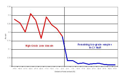
Figure
17-11: Contact Profile of CX HG vs. LG Domains
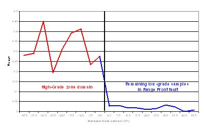
Figure
17-12: Contact Profile of Range Front HG vs. LG Domains
17.5.3 Histograms
and Log-Probability Plots
The
sample data contained in the various domains is displayed in
a series of
histograms and probability plots (Figures 17-13 through 17-24).
The
histograms of the fault zones as a whole show very skewed distributions
of data.
However, once separated, the HG vs. LG histograms are, as expected,
significantly different. The log-probability plots for the
fault zones (Figure
17-19 and Figure 17-22) exhibit subtle breaks in the slope
of the distribution
at a grade of 0.1 opt Au. This feature is more evident in the
Range Front
fault.
This
break is accentuated when the HG and LG data is viewed separately.
For example,
Figure 17-20 shows the distribution of samples inside the CX
HG zone. There are
a series of samples below the 0.1 opt Au threshold for the
HG zone that show a
very different distribution trend when compared to the higher-grade
samples.
These low-grade samples represent narrow intervals which are
bracketed by
higher-grade material and are the result of generalizations
made during the
interpretation of the HG domain boundaries. It is expected
this mixing of
domains will be reduced with additional detailed drilling
information.
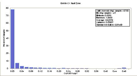
Figure
17-13: Histogram of Gold in CX Fault Zone
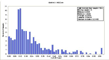
Figure
17-14: Histogram of Gold in CX HG Zone
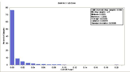
Figure
17-15: Histogram of Gold in CX LG Portion of Fault Zone
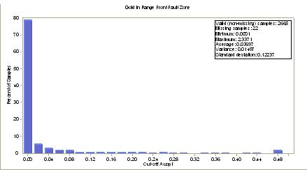
Figure
17-16: Histogram of Gold in Range Front Fault Zone
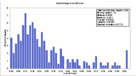
Figure
17-17: Histogram of Gold in Range Front HG Zone
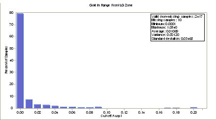
Figure
17-18: Histogram of Gold in Range Front LG Portion of Fault
Zone
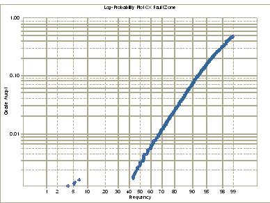
Figure
17-19: Log-Probability Plot of Gold in CX Fault Zone
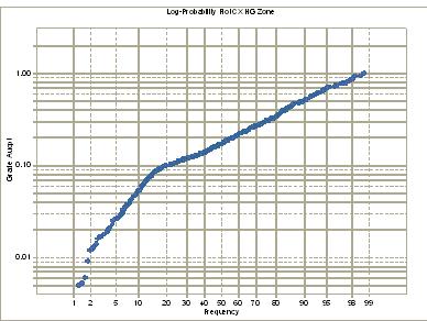
Figure
17-20: Log-Probability Plot of Gold in CX HG Zone
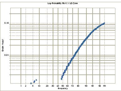
Figure
17-21: Log-Probability Plot of Gold in CX LG Portion of Fault
Zone
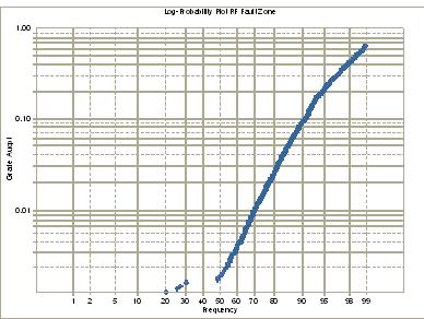
Figure
17-22: Log-Probability Plot of Gold in Range Front Fault Zone
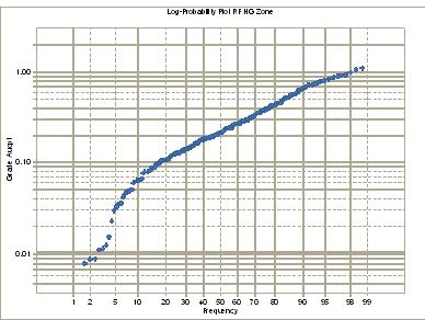
Figure
17-23: Log-Probability Plot of Gold in Range Front HG Zone
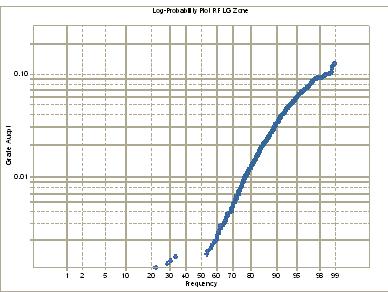
Figure
17-24: Log-Probability Plot of Gold in Range Front LG Portion
of Fault
Zone
17.5.4 Conclusions
and Modeling Implications
The
results of the EDA indicate that the HG zones in the CX and
Range Front fault
zones are truly distinct in nature and should be isolated from
the lower-grade
material during the grade estimation process. This conclusion
is best supported
by the results of the contact profile analysis and the log-probability
distributions of the data.
17.6 Bulk
Density Data
There
are
no individual bulk density values available in the drill-hole
database from
which to conduct interpolation estimations in the block model.
Historical data
derived from the production experience at the ▇▇▇▇▇▇ mine indicates
an average
bulk density tonnage factor of 13 cubic feet per ton of material.
This value has
been retained for this resource estimation.
17.7 Evaluation
of Outlier Grades
The
presence of extreme sample grades was evaluated on the histograms
and
log-probability plots shown in Figures 17-11 through 17-21.
There are few
indications of anomalous values other than a few data points
in the upper grade
range of the Range Front LG portion of the fault zone (a domain
which is not
included in the final resource summary).
A
decile
analysis of the data was also conducted in order to identify
the possible
existence of anomalous values. If the top-decile of the database
contains more
than 40% of the contained gold, or there is more than twice
the contained gold
than the previous (9th) decile, then some form of top-cutting
may be required
and the data must then be evaluated on a finer (percentile)
scale. At this
stage, if there is >10% of the contained gold in a single percentile bin, or
there is more than twice the contained gold than the previous
bin, then some
form of top-cutting may be required. The proportion of gold
in the HG and LG
domains of the CX and Range Front zones is summarized in table
17-4.
Table
17-4: Proportion of Contained Gold in Decile/Percentile of
Samples
|
Percent
of contained gold (%)
|
||||
|
Decile/Percentile
|
CX
HG zone
|
CX
LG Zone
|
RF
HG Zone
|
RF
LG Zone
|
|
80
|
15.2
|
18.8
|
15.1
|
16.0
|
|
90
|
31.4
|
68.3
|
32.0
|
73.1
|
|
98
|
4.4
|
9.1
|
4.7
|
10.2
|
|
99
|
5.3
|
21.3
|
5.3
|
23.0
|
The
results in the table above show that there are no anomalous
values in the two HG
domains. There are 7 samples in the CX HG zone which are greater
than 1 opt Au,
5 of which are less than 1.1 opt Au. The other two samples
(at 1.82 and 1.84 opt
Au) are from drill hole RHA-1567 and are in a thick area of
mineralization with
lots of proximal samples. As a result, the overall effect of
these two
high-grade samples on the resource is minimal.
The
Range
Front HG zone has 5 samples which exceed 1 opt Au. These samples
were found to
be supported by adequate additional proximal samples and it
is felt that no
action with respect to top-cutting is required.
Both
LG
domains contain several high-grade samples which are considered
anomalous. As
stated previously, these are relatively high-grade samples
which do not conform
to the interpretation of the HG domain. Based on the current
understanding of
the nature of the HG zone, these intervals are probably interconnected
with the
main HG portion of the deposit but this interpretation cannot
be supported by
the current density of drilling. Therefore, these few intervals
are essentially
excluded from the resource estimate and are assigned to the
LG zone. The LG
composite samples have been top-cut to a value of 0.25 opt
Au. This involves a
total of 9 samples in the CX LG zone and 5 samples in the Range
Front LG
zone.
17.8 Variography
The
degree of spatial variability in a mineral deposit depends
on both the distance
and direction between points of comparison. Typically, the
variability between
samples increases as the distance between samples also increases.
If the degree
of variability is related to the direction of comparison, then
the deposit is
said to exhibit anisotropic tendencies which can be summarized
with the search
ellipse. The semi-variogram is a common function used to measure
the spatial
variability within a deposit.
The
components of the variogram include the nugget, sill and range.
Often, samples
compared over very short distances (even samples compared from
the same
location) show some degree of variability. As a result, the
curve of the
variogram often begins at some point on the y-axis above the
origin - this point
is called the “nugget”. The nugget is a measure of not only the natural
variability of the data over very short distances but also
a measure of the
variability that can be introduced due to errors during sample
collection,
preparation and assaying.
The
degree of variability between samples typically increases as
the distance
between the samples becomes greater. Eventually, the degree
of variability
between samples reaches a maximum value. This is called the
“sill” and the
distance between samples at which this occurs is referred to
as the
“range”.
The
spatial evaluation of the data in this report has been conducted
using a
correlogram rather than the traditional variogram. The correlogram
is normalized
to the variance of the data and is less sensitive to outlier
values, generally
giving better results.
Correlograms
have been produced from the 5-foot composite drill-hole sample
data for the CX
HG and Range Front HG domains using the commercial software
program Sage 2001
(▇▇▇▇▇▇ and Co). Multidirectional correlograms were generated
at 30o intervals
both horizontally and vertically resulting in a total of 37
sample correlograms
in which an algorithm determines the best-fit model. The sample
correlograms are
included as Appendix
17-1 (CX Correlogram) and Appendix 17-2 (Range Front Correlogram),
and are
summarized in Table 17-5.
17.9 Model
Setup and Limits
Although
the CX and Range Front zones are only separated by about 600
feet, two separate
block models were initialized in order to minimize their size
and thus, reduce
calculation and manipulation times. Both models utilize the
same block size
(10x10x10 ft) and both models have been rotated by 30 degrees
which
approximately aligns it with the general trend of the zones
and reduces the
total number of blocks in the model.
The
limits and orientation of the CX block model are shown in Figure
17-23.
Table
17-5: Variogram Parameters
|
Domain
|
Nugget
|
S1
|
S2
|
1st
Structure
|
2nd
Structure
|
||||
|
Range
(ft)
|
AZ
|
Dip
|
Range
(ft)
|
AZ
|
Dip
|
||||
|
CX
HG
|
0.550
|
0.181
|
0.269
|
461
|
4
|
-3
|
837
|
180
|
22
|
|
157
|
96
|
-32
|
571
|
73
|
37
|
||||
|
9
|
89
|
58
|
40
|
113
|
-45
|
||||
|
RF
HG
|
0.500
|
0.483
|
0.015
|
195
|
94
|
22
|
688
|
8
|
23
|
|
146
|
203
|
38
|
626
|
227
|
61
|
||||
|
8
|
341
|
44
|
305
|
106
|
16
|
||||
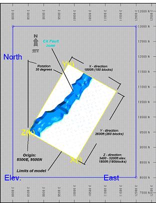
Figure
17-25: CX Zone Block Model Limits
The
CX
zone model limits are summarized in Table 17-6.
Table
17-6: CX Zone Block Model Limits
|
Direction
|
Min
|
Max
|
Size
(ft)
|
#Blocks
|
|
X
|
0
|
1800
|
10
|
180
|
|
Y
|
0
|
2600
|
10
|
260
|
|
Z
|
3400
|
5200
|
10
|
180
|
(Origin
8500E, 9500N rotated 30 degrees from north)
The
limits and orientation of the Range Front block model are shown
in Figure 17-24
and are summarized in Table 17-7
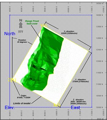
Figure
17-26: Range Front Zone Block Model Limits
Table
17-7: Range Front Zone Block Model Limits
|
Direction
|
Min
|
Max
|
Size
(ft)
|
#Blocks
|
|
X
|
0
|
2200
|
10
|
220
|
|
Y
|
0
|
2700
|
10
|
270
|
|
Z
|
2600
|
5600
|
10
|
300
|
(Origin
8100E, 11200N rotated 30 degrees from north)
17.10 Interpolation
Parameters
The
block
model grade interpolation, by ordinary kriging (OK), was conducted
using
hard-boundary code matching within the Zone domains. This means
that the block
grade estimations within each domain were restricted to drill-hole
samples
located within that domain.
The
results of the OK estimation were compared with the Hermitian
(Herco) polynomial
change of support model (also referred to as the Discrete Gaussian
correction,
this method is described in detail in section 17.11.2) utilizing
a series of
pseudo grade/tonnage distribution curves. Modifications were
made to the krige
interpolation parameters until the desired results were obtained.
The
CX
and Range Front OK models have been generated with a relatively
limited number
samples in order to match the Herco distribution. This approach
reduces the
amount of smoothing (averaging) in the model and, while there
may be some
uncertainty on a localized scale, this approach produces reliable
estimations of
the recoverable grade and tonnage for the overall deposit.
The
interpolation in each zone was conducted using a search ellipse
oriented
sub-parallel to the general trend of the mineralization. The
CX zone uses a
search ellipse measuring 700x700x100 feet oriented at an azimuth
of 40 degrees
and dips -60 degrees SE. The Range Front zone uses an ellipse
measuring
900x900x100 feet at an azimuth of 15 degrees and -65 SE dip.
The
interpolation parameters used for the OK estimate are summarized
in Table
17-8.
Table
17-8: Interpolation Parameters for Ordinary Krige Estimates
|
Domain
|
Search
|
#
Comps
|
|||||
|
Range
(ft)
|
Orientation
(AZ,Dip)
|
Max/Min
per Blk/
|
|||||
|
X
|
Y
|
Z
|
X
|
Y
|
Z
|
Max
per hole
|
|
|
CX
HG
|
700
|
700
|
100
|
130,-60
|
40,0
|
310,-30
|
6/3/2
|
|
RF
HG
|
900
|
900
|
100
|
105,-65
|
15,0
|
285,-25
|
12/4/3
|
For
comparison purposes, grade estimates were also conducted using
both the inverse
distance (IDW) interpolation method and a nearest neighbor
(NN) distribution.
Note that the IDW estimates were also “tuned” in comparison with the Herco
grade/tonnage distribution.
As
stated
previously, the resource estimation is summarized within the
HG zone domains.
However, the gold content in the low-grade portion of the fault
zones has also
been estimated for the purposes of dilution studies in future
mine design
evaluations. The LG zone estimations were made using the relative
elevation IDW
method used in the indicator probability estimates described
in section 17.2.2
of this report.
The
IDW
interpolation parameters are summarized in the table below.
Table
17-9: Interpolation Parameters for IDW Estimates
|
Domain
|
Search
|
#
Comps
|
|||||
|
Range
(ft)
|
Orientation
(AZ,Dip)
|
Max/Min
per Blk/
|
|||||
|
X
|
Y
|
Z
|
X
|
Y
|
Z
|
Max
per hole
|
|
|
CX
HG
|
700
|
700
|
100
|
130,-60
|
40,0
|
310,-30
|
16/5/4
|
|
RF
HG
|
900
|
900
|
100
|
105,-65
|
15,0
|
285,-25
|
30/6/5
|
|
CX
LG
|
700
|
700
|
700
|
Relative
to gold zone trend
|
20/1/4
|
||
|
RF
LG
|
900
|
900
|
900
|
Relative
to gold zone trend
|
20/1/4
|
||
17.11 Validation
The
resource model results were validated in several ways including
a thorough
visual review of the results, comparisons with the change of
support model,
comparisons with other methods and grade distribution comparisons
using swath
plots.
17.11.1 Visual
Inspection
Detailed
visual inspection of the block models has been conducted in
both cross section
and plan. This includes the proper coding and percentage of
blocks with respect
to the respective domains. The distribution of block grades
were also compared
relative to the drill-hole samples in order to ensure proper
representation in
the model. Examples of cross sections showing the drill-hole
and block model
grade distributions are shown in Figure 17-25 for the CX zone
and Figure 17-26
for the Range Front zone. Complete sets of cross sections through
the models are
included in Appendix
17-3.
17.11.2 Model
Checks for Change of Support
The
relative degree of smoothing in the block model estimates were
evaluated using
the Discrete Gaussian of Hermitian Polynomial Change of Support
method
(described by ▇▇▇▇▇▇▇ and Huijbregts, Mining Geostatistics,
1978). With this
method, the distribution of the hypothetical block grades can
be directly
compared to the estimated (OK and IDW) model through the use
of
pseudo-grade/tonnage curves. Adjustments are made to the block
model
interpolation parameters until an acceptable match is made
with the Herco
distribution. In general, the estimated model should be between
5-10% higher in
tonnage and 5-10% lower in grade when compared to the Herco
distribution at the
projected cut-off grade. These differences account for selectivity
and other
potential ore-handling issues which commonly occur during mining.
The
Herco
distribution is derived from the declustered composite grades
that have been
adjusted to account for the change in support as one goes from
smaller
drill-hole composite samples to the large blocks in the model.
The
transformation results in a less skewed distribution but with
the same mean as
the original declustered samples. Note that the standardized
block variance
values resulting from the correlogram-based OK estimate are
multiplied by the
variance of the declustered composite data to obtain relative
block variances
used in the Herco analysis.
Comparisons
between the krige/IDW and Herco models are shown foe the CX
and Range Front HG
zones in Figures 17-27 and 17-28.
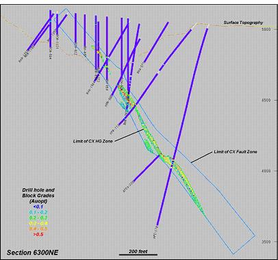
Figure
17-27: CX HG Zone Drill Hole and Block Grade Distribution
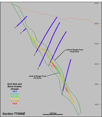
Figure
17-28: Range Front HG Zone Drill Hole and Block Grade Distribution
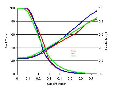
Figure
17-29: CX HG Zone Krige/IDW/Herco Plots
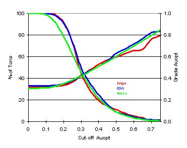
Figure
17-30: Range Front HG Zone Krige/IDW/Herco Plots
The
results show good correlation at a typical cut-off limit for
an underground
operation of between 0.2 and 0.3 opt Au. The separation of
the lines at higher
cut-offs are an indication that the OK model may underestimate
the higher-grade
portions of the deposit and, conversely, the IDW model may
slightly overestimate
the higher grades.
17.11.3 Comparison
of Interpolation Methods
The
OK,
IDW and NN models are tabulated for comparison purposes in
Table
17-10.
Table
17-10: Comparison of Interpolation Methods
|
Cut-off
|
OK
Model
|
IDW
Model
|
NN
Model
|
|||
|
(Auopt)
|
kTons
|
Auopt
|
kTons
|
Auopt
|
kTons
|
Auopt
|
|
CX
Zone :
|
||||||
|
0
|
2,052
|
0.25
|
2,052
|
0.24
|
2,052
|
0.24
|
|
0.15
|
1,718
|
0.27
|
1,744
|
0.26
|
1,149
|
0.36
|
|
0.2
|
1,404
|
0.29
|
1,242
|
0.29
|
880
|
0.41
|
|
0.25
|
982
|
0.32
|
658
|
0.35
|
687
|
0.46
|
|
0.3
|
419
|
0.39
|
397
|
0.40
|
514
|
0.53
|
|
RF
Zone :
|
||||||
|
0
|
4,298
|
0.32
|
4,298
|
0.33
|
4,298
|
0.31
|
|
0.15
|
4,251
|
0.33
|
4,215
|
0.34
|
3,167
|
0.38
|
|
0.2
|
3,952
|
0.34
|
3,903
|
0.35
|
2,499
|
0.44
|
|
0.25
|
3,145
|
0.36
|
3,157
|
0.38
|
2,099
|
0.48
|
|
0.3
|
1,908
|
0.42
|
2,131
|
0.43
|
1,539
|
0.55
|
The
variance on gold grades in the OK and IDW models is less generally
than 5% at
all cut-off limits. Local variances in tonnage and grade occur
primarily at
depth, where the drill-hole spacing increases.
17.11.4 Swath
Plots
A
swath
plot is a graphical display of the grade distribution derived
from a series of
bands, or swaths, generated in several directions through the
deposit. The grade
variations from the OK and IDW models are compared using the
swath plot to the
distribution derived from the declustered (NN) grade model.
On
a
local scale, the NN model does not provide reliable estimations
of grade but, on
a much larger scale, it represents an unbiased estimation of
the grade
distribution based on the underlying data. Therefore, if the
OK and IDW models
are considered unbiased, their grade trends may show local
fluctuations on a
swath plot but, the overall trend should be similar to the
NN distribution of
grade.
Swath
plots have been generated for the gold grade distribution in
both the CX HG
zone, shown in Figures 17-29, 17-30 and 17-31 and the Range
Front HG zone shown
in Figures 17-32, 17-33 and 17-35. It should be noted that
the 50-foot wide
swaths have been applied to the rotated block model. Therefore,
the X-axis
increments in the plots are listed by swath number, rather
than actual mine grid
coordinate values.
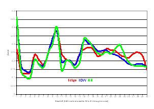
Figure
17-31: Swath Plot CX HG Zone, East-West
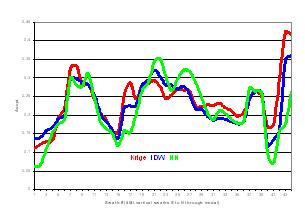
Figure
17-32: Swath Plots CX HG Zone, North-South
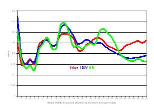
Figure
17-33: Swath Plot CX HG Zone, Vertical
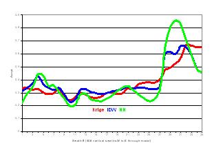
Figure
17-34: Swath Plot Range Front HG Zone, East-West
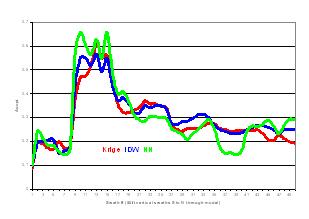
Figure
17-35: Swath Plot Range Front HG Zone, North-South
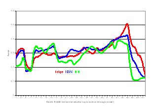
Figure
17-36: Swath Plot Range Front HG Zone, Vertical
There
are
local fluctuations which tend to increase in intensity at depth
or along the
fringes of the deposits where the drilling spacing tends to
increase. In
general, the results are similar between the models with no
indications of
significant grade bias.
17.12 Resource
Classification
A
common
method used in the classification of mineral resources involves
geostatistical
methods that define categories based on the confidence limits
of the estimation.
Measured resources are defined as material in which the predicted
grades are
within ±15% accuracy on a quarterly basis, at a 90% confidence limit.
In other
words, there is a 90% chance that the predicted grades for
a quarter-year of
production will be within ±15% of the actually achieved production grades.
Similarly, Indicated resources include material in which the
yearly production
grades are estimated with ±15% accuracy at the 90% confidence
limit.
The
method is based on the large sample normal theory that assumes
that as the grade
estimations from smaller blocks are combined into larger ones,
the errors of the
estimation become normally distributed (as described by ▇.
▇▇▇▇▇, 1997). The
steps in generating the classification parameters for the CX
and Range Front
zones are described as follows.
This
exercise assumes a nominal daily production rate from either
of the zones of 500
tons per day which equates to a monthly production rate of
approximately 15,000
tons per month. At an average tonnage factor of 13 cubic feet
per ton, a block
measuring 60x60x60 feet represents approximately one month
of production (16,600
tons).
A
block
equal in size to the volume of one month’s production is created and the kriging
variance is determined using a series of theoretical drill
holes at intervals
averaging 50, 100 and 200 foot spacing. The calculations are
done over a series
of drill-hole grids in order to evaluate the variation in the
results with
respect to the spacing of the drill data.
The
correlogram used to determine the kriging variance in the large
block is derived
from the actual gold sample data which has been composited
to 5-foot intervals
(Table 17-5). Because the correlogram was used, the normalized
block kriging
variance (a variable which is output from the OK run) was standardized
to the
underlying data by multiplying by the square of the coefficient
of variation
(CV=std dev/mean from the original 5 ft composite data).
The
relative standard error for a quarter year of production is
determined by taking
the square root of the standard block variance divided by three
(i.e. divide by
3 for a quarter-yr of production or divide by 12 in order to
determine the error
for a full year of production). Finally, the 90% confidence
limit is determined
by multiplying the relative standard error by 1.645. The results
of the exercise
are listed in Table 17-11 and shown in graphical form in Figure
17-37.
Table
17-11: Quarterly and Yearly Confidence Limits Determination
|
DH
|
Norm
OK
|
Std.
|
Relative
Std. Error
|
Conf.
@ 90% Limit
|
|||
|
Spacing
(ft)
|
Blk.Var.
|
(CV)sqd
|
Blk.Var.
|
Qtr
|
Year
|
Qtr
|
Year
|
|
CX
Zone:
|
|||||||
|
200
|
0.1569
|
0.833
|
0.1307
|
0.2088
|
0.1044
|
34.3%
|
15.2%
|
|
100
|
0.0546
|
0.833
|
0.0455
|
0.1233
|
0.0616
|
20.3%
|
10.1%
|
|
50
|
0.0409
|
0.833
|
0.0341
|
0.1068
|
0.0533
|
15.6%
|
8.8%
|
|
Range
Front Zone:
|
|||||||
|
200
|
0.1035
|
0.886
|
0.0915
|
0.1549
|
0.0874
|
28.8%
|
14.4%
|
|
100
|
0.0761
|
0.886
|
0.0674
|
0.1499
|
0.0750
|
24.7%
|
12.3%
|
|
50
|
0.0371
|
0.886
|
0.0329
|
0.1047
|
0.0523
|
15.2%
|
8.6%
|
Figure
17-37: Confidence Limits Distribution by Drill-hole Spacing
The
results of the exercise are very similar for both the CX and
Range Front zones.
A quarter of a year of production can be estimated at +/-15%
accuracy at the 90%
confidence limit with drill holes spaced at approximately 35-foot
intervals
(projected from the trends exhibited in Figure 17-35). Similarly,
one year of
production can be estimated at the same confidence levels with
drill holes
spaced at 175-200 foot intervals. (Note that an even grid of
drill holes spaced
at 200- foot intervals would result in the maximum distance
from a block in the
model to a drill-hole sample location of 125 feet).
Some
additional factors that were considered in the designation
of classification
parameters are summarized as follows:
| · |
The
▇▇▇▇▇▇ deposits are geologically similar to others
in the area and the
mode of formation is well understood. The nearby
▇▇▇▇▇▇▇▇ deposit base its
classification on the spacing of drill holes. Measured
resources vary (by
zone) from between 50-100 feet. Indicated resources
are defined by drill
holes spaced at 150-foot intervals.
|
| · |
The
CX Zone was in operation and is currently exposed
on surface in the walls
and floor of the CX pit. This exposure provides information
regarding the
nature and continuity of the zone and greatly increases
the degree of
confidence in this portion of the
deposit.
|
Ultimately,
the classification definitions are based on the confidence
in the continuity of
the mineralization and are expressed based on the distance
and proximity to the
drill-hole sample locations. The upper portion of the CX zone
has been upgraded
to a higher classification due to its exposure on surface.
Typically,
a strict numerical classification based on “distance to” protocols can produce
minor patches or islands of blocks within large continuous
zones of a different
class. Retaining these “artifacts” inflicts a certain degree of clutter and
confusion when visually reviewing the distribution of resource
classes in the
model. Secondly, the locally complex class designation gives
an impression of
detail or complexity in the designation which is often not
supported by the
current density of drilling. Therefore, some local generalizations
were made -
manually re-classified in order to produce a cleaner and more
consistent class
distribution. These manual changes are described as follows.
The CX zone
“measured” criteria (3 holes within an average distance of 75 feet) included
zones which extended below 300 feet below surface - these areas
were
reclassified (downgraded) as indicated material. The original
contact between
indicated and inferred material in the Range Front zone was
somewhat ragged in
places and was more clearly defined through some minor manual
reclassification.
Ultimately, these changes are considered relatively minor and
are implemented to
make the various class designations more clearly defined and
more visually
apparent.
The
resource classification parameters are defined as follows.
Measured
Resources:
Material located within the high-grade domain which meets the
two criteria as
follows: Blocks which have been estimated by a minimum of three
drill holes
within an average distance of 75 feet and, second, which are
within a maximum
distance of 300 feet from surface exposures created during
previous production
activities. This includes only material in the vicinity of
the CX
pit.
Indicated
Resources:
Blocks
which do not meet the criteria for measured resources but include
material
located within the high-grade zone in which grades have been
estimated by a
minimum of three drill holes within a maximum average distance
of 125
feet.
Inferred
Resources:
The
remaining blocks in the high-grade zone which do not meet the
criteria for
measured or indicated resources. Internally, this is based
on drill holes with a
maximum spacing of 400 feet in the CX zone and up to 600 feet
in the Range Front
zone. On the peripheries of the deposit, which is not “closed” by drilling, the
resource extends a maximum distance of 150 feet from a drill
hole.
The
distribution of resources by class in the CX and Range Front
zones is shown in
Figures 17-38 and 17-39.
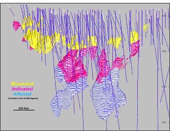
Figure
17-38: CX Zone Resource Classification
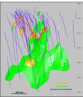
Figure
17-39: Range Front Zone Resource Classification
17.13 Key
Assumptions of Economic and Technical Parameters
Generalized
economic and technical parameters have been estimated for the
▇▇▇▇▇▇ project in
order to project the relative scale of the potential economic
viability of the
operation and it’s contained mineral resources. It is important to recognize
that this is a series of initial assumptions and does not represent
an economic
analysis for this project. As a result, this report contains
only mineral
resources and does not
include
mineral reserves for the ▇▇▇▇▇▇ deposits.
The
key
economic and technical assumptions, parameters and methods
used in this report
are primarily derived from proximal existing operations in
the ▇▇▇▇▇▇ area. Many
of the mines in Northern Nevada exhibit similar ore type, exploitation
methods
and metallurgical characteristics. The key assumptions are
listed as
follows:
|
1)
|
Underground
mining utilizing underhand, drift-and-fill exploitation
methods. Cost
estimated at US$50/ton of ore mined (inclusive
of backfill costs). These
costs are based upon the Company’s initial negotiations of contract rates
for mining and development work with Small Mine
Development
(“SMD”).
|
|
2)
|
Access
to the mineralized zones will be via ramp/decline
beginning from the
bottom of the existing CX-pit
floor.
|
|
3)
|
The
daily production rate from the combined Range
Front and CX zones is
estimated to be 700 tons per day.
|
|
4)
|
▇▇▇▇▇▇-type,
refractory gold ore (similar to Getchell, Meikle,
Jerritt Canyon, Deep
Star mines), with recoveries estimated to be
93%.
|
|
5)
|
Processed
by toll milling at third-party mill (Newmont’s Twin Creeks, Gold Quarry,
or Lone Tree ▇▇▇▇▇; ▇▇▇▇▇▇▇’▇ Goldstrike complex; and/or Queenstake’s
Jerritt Canyon mill). Toll milling costs are
estimated to be $25/ton
milled, including transportation. This is based
on initial discussions
between Atna and the third-party operators and
assumes that 100% of ▇▇▇▇▇▇
ore will require either autoclave or roaster
processing.
|
|
6)
|
Site
indirect and administrative costs (General and
Administrative costs) are
estimated to be approximately
$7/ton.
|
|
7)
|
Projected
gold price of $400/oz.
|
The
“base
case” cut-off grade is calculated as follows:
Mining
($50/t) + Milling ($25/t) + G&A ($7/t) = total operating cost of
$82/ton
Gold
price of $400/oz / 34.286 = $11.67/gram
|
Total
Cost / gold price:
|
$82/t
/ ($400/34.286)
|
|
Recovery:
|
(93/100)
|
|
=7.56g,
or 0.22optAu
|
(Base
case cut-off rounded to 0.20optAu in tables)
17.14 Mineral
Resources
The
mineral resources are summarized for the CX zone in Table 17-12,
the Range Front
zone in Table 17-13 and for both zone combined in Table 17-14.
Table
17-12: Mineral Resource, CX Zone
|
Category
|
Cut-off
(Au opt)
|
Tons
(000)
|
Grade
(Auopt)
|
Contain
Au (koz)
|
|
Measured
|
0.15
|
445
|
0.27
|
119
|
|
0.20
|
319
|
0.30
|
97
|
|
|
0.25
|
213
|
0.34
|
73
|
|
|
0.30
|
130
|
0.39
|
50
|
|
|
Indicated
|
0.15
|
502
|
0.28
|
143
|
|
0.20
|
427
|
0.30
|
130
|
|
|
0.25
|
278
|
0.34
|
96
|
|
|
0.30
|
156
|
0.40
|
63
|
|
|
Measured
+
|
0.15
|
947
|
0.28
|
262
|
|
Indicated
|
0.20
|
746
|
0.30
|
226
|
|
0.25
|
490
|
0.34
|
169
|
|
|
0.30
|
286
|
0.40
|
113
|
|
|
Inferred
|
0.15
|
770
|
0.27
|
205
|
|
0.20
|
658
|
0.28
|
185
|
|
|
0.25
|
491
|
0.30
|
148
|
|
|
0.30
|
134
|
0.36
|
48
|
(Base
case cut-off grade = 0.20optAu)
Table
17-13: Mineral Resource, Range Front Zone
|
Category
|
Cut-off
(Au opt)
|
Tons
(000)
|
Grade
(Auopt)
|
Contain
Au (koz)
|
|
Measured
|
0.15
|
0
|
0
|
0
|
|
0.20
|
0
|
0
|
0
|
|
|
0.25
|
0
|
0
|
0
|
|
|
0.30
|
0
|
0
|
0
|
|
|
Indicated
|
0.15
|
811
|
0.32
|
257
|
|
0.20
|
721
|
0.33
|
241
|
|
|
0.25
|
582
|
0.36
|
210
|
|
|
0.30
|
429
|
0.39
|
167
|
|
|
Measured
+
|
0.15
|
811
|
0.32
|
257
|
|
Indicated
|
0.20
|
721
|
0.33
|
241
|
|
0.25
|
582
|
0.36
|
210
|
|
|
0.30
|
429
|
0.39
|
167
|
|
|
Inferred
|
0.15
|
3,440
|
0.33
|
1,127
|
|
0.20
|
3,231
|
0.34
|
1,088
|
|
|
0.25
|
2,562
|
0.37
|
936
|
|
|
0.30
|
1,479
|
0.43
|
642
|
(Base
case cut-off grade = 0.20optAu)
Table
17-14: Mineral Resource, Combined CX and Range Front Zones
|
Category
|
Cut-off
(Au opt)
|
Tons
(000)
|
Grade
(Auopt)
|
Contain
Au (koz)
|
|
Measured
|
0.15
|
445
|
0.27
|
119
|
|
0.20
|
319
|
0.30
|
97
|
|
|
0.25
|
213
|
0.34
|
73
|
|
|
0.30
|
130
|
0.39
|
50
|
|
|
Indicated
|
0.15
|
1,313
|
0.30
|
400
|
|
0.20
|
1,148
|
0.32
|
371
|
|
|
0.25
|
860
|
0.36
|
305
|
|
|
0.30
|
585
|
0.39
|
230
|
|
|
Measured
+
|
0.15
|
1,758
|
0.30
|
519
|
|
Indicated
|
0.20
|
1,467
|
0.32
|
467
|
|
0.25
|
1,073
|
0.35
|
379
|
|
|
0.30
|
715
|
0.39
|
281
|
|
|
Inferred
|
0.15
|
4,211
|
0.32
|
1,332
|
|
0.20
|
3,889
|
0.33
|
1,273
|
|
|
0.25
|
3,054
|
0.36
|
1,084
|
|
|
0.30
|
1,612
|
0.43
|
690
|
(Base
case cut-off grade = 0.20optAu)
18.0 Other
Relevant Data and Information
Two
drill
holes were completed after the cut-off date for data included
within this
Technical report. APRF-229A and APRF-230, illustrated in Figure
18-1, were both
finalized after February 15th,
2005,
the effective date of this report.
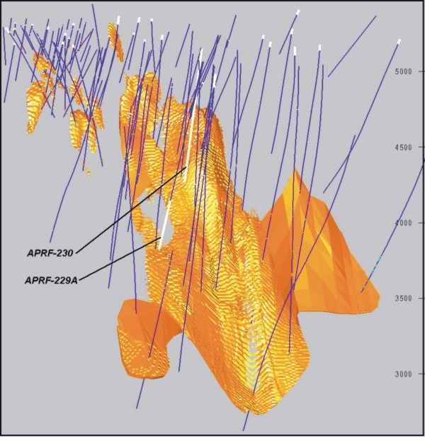
Figure
18-1. Location of Final Phase I Range Front Holes (APRF-229A
and
APRF-230)
The
assay
results from these two holes, shown below in Table 18-1, are
as
follows:
Table
18-1: Significant Drill Results From Holes APRF-229A and APRF-230
|
Drill-hole
ID
|
Total
Depth
|
From
(ft.)
|
To
(ft.)
|
Intercept
Length (ft.)
|
Intercept
Length (meters)
|
Grade
(ounce/ton) Gold
|
Grade
(gram/tonne) Gold
|
|
APRF-229A
|
1,515.0
|
1,466.0
|
1,474.5
|
8.5
|
2.59
|
0.458
|
15.70
|
|
APRF-230
|
924.5
|
730.0
|
736.0
|
6.0
|
1.83
|
0.635
|
21.78
|
|
including
|
734.0
|
736.0
|
2.0
|
0.61
|
1.108
|
37.97
|
Drill
hole APRF-229A cut mineralization consistent with mineralization
extrapolated
from drill holes completed prior to the data cut-off date for
this report and
these results will not materially effect the results reported
within this
Technical Report. Drill hole APRF-230 was lost due to poor
drilling conditions
prior to fully penetrating the targeted Range Front zone. APRF-230
did cut
significant mineralization well above the zone, as displayed
above in Table
18-1. However, because this mineralized intercept is outside
the resource
evaluation envelopes, this data will have no effect on the
resource calculation
completed within this Technical Report.
19.0 Interpretation
and Conclusions
Current
data indicates the ▇▇▇▇▇▇ property contains two major zones
of gold
mineralization typical of other gold deposits in the district
and region. The CX
and Range Front zones are major brittle structural features
that focused
hydrothermal fluid flow and gold mineralization. Analytical
results from
drilling completed through February 15, 2005 by Atna and previous
operators has
outlined two gold-bearing mineral zones which remain open in
several areas along
strike and dip. These two zones display numerous physical and
geochemical
similarities to the neighboring ▇▇▇▇▇▇▇▇, Turquoise Ridge,
and Twin Creeks
Mines, all of which are considered ▇▇▇▇▇▇-type, sediment-hosted
gold deposits
and are currently being commercially exploited. Drill-hole
intercept data is
sufficiently dense within the CX and Range Front zones to provide
an adequate
level of confidence for the resource estimates established
in Section 17 of this
report.
The
resource modeling techniques utilized in this Technical Report
are considered
consistent with practices currently in use in the mining industry.
The density
of the current drill coverage, primarily at depth, is relatively
wide-spaced
and, as a result, a high proportion of the resource remains
in the Inferred
category. Additional drilling is required to raise confidence
levels,
particularly in the deeper portions of both the CX and Range
Front, where
drill-hole ▇▇▇▇▇▇-points are generally on greater than 200-foot
centers. Future
drilling campaigns are planned with this objective in view,
and should be part
of an overall program to complete a pre-feasibility study,
mine plan and
establish mineral reserves within the CX and Range Front zones.
20.0 Recommendations
The
next
exploration phase at the project should focus on more fully
defining the nature
and distribution of gold within the Range Front and CX resource
blocks. This
phase should focus on the continuation of shallow Range Front
surface drilling,
and on development of underground access to both the Range
Front and CX mineral
zones.
Drilling
in the shallow Range Front environment will enhance definition
of newly
discovered gold resources lying above 4500' elevation (see
Figure 9-2).
Development of underground access will provide platforms for
expanded drilling
of the existing resource blocks in both fault zones (see Figure
17-2) and raise
the confidence level attributable to these blocks. An initial
drill spacing of
100-feet by 100-feet (both surface and underground) is recommended
for the
shallow portion of the Range Front zone to refine the understanding
of the
geology, structural controls and detailed distribution of gold
grades.
Detailed
drilling will also refine the variography for future resource
modeling and
define the appropriate drill spacing for reserve development.
It will also
generate sufficient mineralized material for preliminary metallurgical
testing
and process metallurgical planning.
Once
detailed drilling is completed (or substantially completed)
on the upper Range
Front zone, the underground workings should be extended into
the mineralized
zone and a bulk sample collected for detailed metallurgical
testing.
Development
of underground access and bulk sampling of the mineralized
zone(s) will provide
necessary cost and planning data for development of an economically
sound mine
plan allowing profitable exploitation of the gold resources
outlined and
discussed in this Technical Report.
After
establishing an initial exploration level for resource definition
drilling, the
underground workings should be extended as a decline to provide
access to deeper
levels of the mineral zones for continued up-grading of the
resource confidence
levels and conversion of the “Inferred Resource” blocks into Indicated and/or
Measured resource categories. A minimum drill-hole spacing
of 200-foot centers
is necessary to evaluate the deeper resource blocks, based
upon the current
data. The drilling recommended in the shallow portions of the
Range Front zone
will directly influence the appropriate drill-hole spacing
throughout the
deposit(s), and it is certain that additional work will be
necessary as deeper
underground access is achieved and reserve development drilling
is being
conducted.
All
underground workings should be structurally and geologically
mapped in detail -
a scale of 1:240 (1 inch = 20 feet) is recommended. A face-and-rib
sampling
program should be maintained throughout the underground drifting
program, and
the collected data added to the resource modeling database.
Concurrent
with the development of the underground access, several reverse
circulation
rotary drill holes should be “twinned” with core holes. It is recommended that
at least six (6) earlier reverse circulation rotary drill holes
be twinned with
core holes designed to cut the mineralized zone within ten
(10) feet of the
existing drill-hole intercepts. Several of these holes may
be completed as
underground drill holes as part of the definition drill program
outlined above.
If the core results are comparable to the original RC sample
results, this
exercise will validate RC sample integrity and bolster the
confidence level of
these intercept values within the database.
Detailed
surface mapping and sampling of the CX mineral zone is recommended
within the CX
pit (where pit wall and bench conditions are sufficiently safe
to allow such
work). Mapping at a scale of 1:240 and detailed continuous
channel sampling of
the bench walls perpendicular to the strike of the mineralized
zone are
recommended. Results from this work will then be added to the
resource database
and models.
Exploratory
drilling along strike and down-dip of the zones is justified,
as both the CX and
Range Front zones remain open to expansion. While not the subject
of this
Technical Report, which focuses on the CX and Range Front mineralized
zones,
additional zones of exploitable mineralization may also be
discovered in
association with the numerous drill-hole gold intercepts which
occur well
outside the mineralized envelopes used in this study. Additional
exploration
drilling is warranted and recommended as work progresses on
the
project.
As
an
adjunct of the additional drilling and underground work discussed
above, work
should continue on elimination of database errors both within
the existing data
set and on all new data added to the database. Atna’s current procedures are
ensuring data reliability and integrity, but continued vigilance
is an integral
part of making successful economic decisions as the project
progresses towards
exploitation.
20.1 Recommended
Program and Budget
Based
upon the recommendations described above, a program has been
designed to focus
on the Range Front zone’s mineralization between the surface and the 4,400-foot
level where both thicknesses and grades best suited for the
project’s initial
development (if reserves are established). The following program
and budget has
been designed with the initial focus on the Range Front zone
mineralization
above the 4,400-foot level:
|
Surface
Drilling-Range Front Zone
|
US$
|
|
Rotary
pre-collar drilling
|
|
|
20
holes, 7,500 feet @ US$25/foot
|
$187,500
|
|
Diamond
core drilling (core-tails)
|
|
|
20
holes, 8,500 feet @ US$50/foot
|
$425,000
|
|
Surface
drill sample prep., assays & standards
|
|
|
5,000
samples @ $20/sample
|
$100,000
|
|
Surface
roads and drill pads (dozer work)
|
$10,000
|
|
Underground
Drilling-Range Front Zone
|
|
|
32
holes, 16,000 feet @ US$50/foot
|
$800,000
|
|
Underground
drill sample prep., assays & standards
|
|
|
5,000
samples @ $20/sample
|
$100,000
|
|
Drilling
subtotal
|
$1,622,500
|
|
Metallurgical
Testing
|
|
|
Sample
compositing, direct cyanidization, roasting, and
autoclave
testing
|
$100,000
|
|
Metallurgical
subtotal
|
$100,000
|
|
Underground
adit/drill crosscut development
|
|
|
Contractor
mobilization
|
$100,000
|
|
Portal
Development
|
$75,000
|
|
Ventilation
- gen sets
|
$125,000
|
|
3,500
feet of drifting @ US$1,200/foot
|
$4,200,000
|
|
Mining
subtotal
|
$4,500,000
|
|
Dewatering
|
|
|
Dewatering
well development
|
|
|
2
-
28 inch ▇▇▇▇▇ @ 600 feet
|
$1,500,000
|
|
Pumps,
piping, & discharge area development
|
$1,000,000
|
|
Dewatering
subtotal
|
$2,500,000
|
|
Permitting
|
|
|
Consulting
fees, permitting, groundwater, etc
|
$150,000
|
|
Reclamation
bonding
|
$500,000
|
|
Permitting
subtotal
|
$650,000
|
|
Project
Team - personnel
|
|
|
Project
manager (engineering)
|
$100,000
|
|
Project
geologist
|
$100,000
|
|
3-Support
geologists
|
$240,000
|
|
3-geotech
|
$150,000
|
|
1-administrative/accounting
|
$60,000
|
|
Personnel
subtotal
|
$650,000
|
|
Land
costs
|
|
|
Land
payments & claim fees and expenses
|
$250,000
|
|
Land
costs subtotal
|
$250,000
|
|
Miscellaneous
costs
|
|
|
Rentals
(field vehicles)
|
$50,000
|
|
Field
materials and supplies
|
$100,000
|
|
Office
materials, office utilities
|
$50,000
|
|
Project
insurance
|
$100,000
|
|
Computers,
software, & all other
|
$100,000
|
|
Miscellaneous
costs subtotal
|
$400,000
|
|
Project
total
|
$10,672,500
|
|
Contingency
@ ~12%
|
$1,324,500
|
|
Proposed
Project Budget
|
$12,000,000
|
References
Arehart,
G.B., ▇▇▇▇▇▇▇▇▇, A.M., ▇▇▇▇▇▇▇, D.R., ▇▇▇▇▇▇▇▇▇▇▇, ▇.▇., ▇▇▇▇▇▇▇,
▇.▇. and
▇▇▇▇▇▇▇▇, ▇.▇., 2003, Evaluation of radioisotope dating of
▇▇▇▇▇▇-type deposits
in the Great Basin, western North America, and implications
for deposit genesis:
Economic Geology, v. 98, p. 235-248.
Benchmark
Maps, 2003, Nevada road and recreation atlas: Medford, OR;
95 p.
Bureau
of
Land Management (BLM, Winnemucca Field Office), 2001, Granite
creek
administrative draft environmental assessment N63-EA01-xx,
prepared for ▇▇▇▇▇▇
Mining Company, 47 ▇.
▇▇▇▇▇▇▇▇▇,
▇., ▇▇▇▇▇▇▇▇▇, ▇., ▇▇▇▇▇▇▇▇, M., ▇▇▇▇▇▇, B. and ▇▇▇▇▇▇▇, E.,
2000, Geologic
overview of the ▇▇▇▇▇▇▇▇ Gold Mine geology, exploration and
ore deposits,
Humboldt County, Nevada, in
▇▇▇▇▇▇▇▇, A.E.J. (ed.). Geology and ore deposits 2000: the
Great Basin and
beyond: Geological Society of Nevada Symposium Proceedings,
Field Trip # 9,
Geology and ore deposits of the ▇▇▇▇▇▇▇▇ region, Humboldt County,
Nevada, p.
113-121.
▇▇▇▇▇,
▇.▇., 2004, Introduction to ▇▇▇▇▇▇-type deposits: Soc. Econ.
Geologists
Newsletter, No. 59 (Oct. 2004), p. 1.
▇▇▇▇▇▇▇▇,
▇.▇., 2000, Overview of regional geology and tectonic setting
of the ▇▇▇▇▇▇
Mountains region, Humboldt County, Nevada, in
▇▇▇▇▇▇▇▇, A.E.J. (ed.). Geology and ore deposits 2000: the
Great Basin and
beyond: Geological Society of Nevada Symposium Proceedings,
Field Trip # 9,
Geology and ore deposits of the ▇▇▇▇▇▇▇▇ region, Humboldt County,
Nevada, p.
69-83.
▇▇▇▇▇,
▇.▇., 1997, Some Methods of Producing Interval Estimates for
Global and Local
Resources: SME Preprint 97-5,4p.
▇▇▇▇▇,
D.A. and ▇▇▇▇▇▇▇, ▇.▇., 1999, Gold and silver resources in
Nevada: Nev. Bureau
of Mines & Geology Map 120.
▇▇▇▇▇▇▇,
▇., 2004, Internal company memoranda.
▇▇▇▇▇▇▇▇,
▇.▇. and ▇▇▇▇▇, ▇.▇., 1974, Geologic Map of the Iron Point
Quadrangle, Humboldt
County, NV: U.S. Geological Survey Geologic Quadrangle Map
GQ-1175, scale
1:24,000.
▇▇▇▇▇▇,
▇.▇. and ▇▇▇▇▇▇▇▇▇▇, E.L., 1991, Geology of the MAG deposit,
▇▇▇▇▇▇ Mine,
Humboldt County, Nevada, in
▇▇▇▇▇▇,
▇.▇., ▇▇▇▇▇, R.E., ▇▇▇▇▇▇▇, ▇.▇., and ▇▇▇▇▇▇▇▇▇, ▇.▇. (eds.),
Geology and ore
deposits of the Great Basin: Geological Society of Nevada,
1990 Symposium
Proceedings, p. 845-856.
▇▇▇▇▇▇,
▇.▇., 1994, Gold in ▇▇▇▇▇▇▇▇ framboidal pyrite in deep CX core
hole DDH-1541:
Unpublished ▇▇▇▇▇▇ Mining Company Report, June 21, 1994.
▇▇▇▇,
B.,
▇▇▇▇▇▇▇, S., ▇▇▇▇, K. and ▇▇▇▇▇▇▇, T., 2004, ▇▇▇▇▇▇ Joint Venture
Field Trip,
in
▇▇▇▇▇▇▇▇, R., ▇▇▇▇▇▇▇, E. and ▇'▇▇▇▇▇▇, P. (eds.), Geological
Society of Nevada
Special Publication No. 40: New discoveries, exploration and
mining activities
along the central and southern Battle Mountain-Eureka trend,
Lander and Eureka
Counties, Nevada, p. 91-115.
Hofstra,
A.H. and ▇▇▇▇▇, ▇.▇., 2000, Characteristics and models for
▇▇▇▇▇▇-type gold
deposits: Reviews in Economic Geology, v. 13, p. 163-220.
▇▇▇▇▇▇,
R.P. and ▇▇▇▇▇▇, M.D., 1997, An amagmatic origin of ▇▇▇▇▇▇-type
gold deposits:
Economic Geology, v. 92, p. 269-288.
▇▇▇▇▇▇▇▇,
▇.▇. and ▇▇▇▇▇▇, ▇.▇., 2004, ▇▇▇▇▇▇-type and distal-disseminated
Au-Ag deposits:
Related distal expressions of Eocene intrusive centers in north-central
Nevada:
Soc. Econ. Geologists Newsletter, No. 59 (Oct. 2004), p. 12-14.
▇▇▇▇▇,
▇.▇., 1991, Tectonic significance of Paleozoic and early Mesozoic
terrane
accretion in northern Nevada: University of California, Berkeley,
Ph.D.
dissertation, 256 p., 3 maps.
▇▇▇▇▇▇▇▇▇▇,
▇.▇., circa 1983, Guidebook geology of the ▇▇▇▇▇▇ Mine. Unidentified
report, 10
▇.
▇▇▇▇▇▇▇▇▇,
D.G., ▇▇▇▇▇▇▇, M. and ▇▇▇▇▇▇▇, V., 1997, Geology at the Twin
Creeks Mine,
Humboldt County, Nevada: History, Development, Operations and
Potential.
Unpublished report.
▇▇▇▇▇▇-▇▇▇▇▇▇▇,
▇.▇. and ▇▇▇▇▇, ▇. ▇., 1991, Lower Paleozoic host rocks in
the ▇▇▇▇▇▇▇▇ gold
belt: Several distinct allocthons or a sequence of continuous
sedimentation?:
Geology, v.19, p. 489-492.
▇▇▇▇▇▇▇▇▇,
▇.▇., ▇▇▇▇▇▇▇▇▇▇▇, ▇.▇. and ▇.▇.▇▇▇▇▇▇▇▇, 2000, The gold deposits
of ▇▇▇▇▇▇
Mining Company: a review of the geology and mining history
through 1999,
Humboldt County, Nevada, in
▇▇▇▇▇▇▇▇, A.E.J. (ed.). Geology and ore deposits 2000: the
Great Basin and
beyond: Geological Society of Nevada Symposium Proceedings,
Field Trip # 9,
Geology and ore deposits of the ▇▇▇▇▇▇▇▇ region, Humboldt County,
Nevada, p.
123-153.
Nevada
Department of Employment, Training & Rehabilitation, 2004.
(▇▇▇▇://▇▇▇▇.▇▇▇▇▇.▇▇.▇▇/▇▇▇/▇▇▇▇/▇▇▇▇▇/▇▇▇▇▇▇.▇▇▇)
▇▇▇▇▇▇▇,
▇., 2004, Internal company memoranda.
▇▇▇▇▇▇▇▇,
▇. and ▇▇▇▇▇▇, M.D., 2004, Enigmatic origin of ▇▇▇▇▇▇-type
deposits: an
amagmatic solution?: Soc. Econ. Geologists Newsletter, No.
59 (Oct. 2004), p.
14-16.
Sierra
Pacific Economic Development Office, 2004.
(▇▇▇▇://▇▇▇▇▇▇▇.▇▇▇▇▇▇▇▇▇▇▇▇▇.▇▇▇/▇▇▇▇/▇▇▇▇▇▇/▇▇▇▇▇▇▇▇/▇▇▇_▇▇▇▇▇▇▇▇/)
▇▇▇▇▇▇▇,
▇.▇., ▇▇▇▇▇▇. S.E., ▇▇▇▇▇▇▇▇, D.R. and ▇▇▇▇▇▇, ▇.▇., 1998,
Deposition of gold in
▇▇▇▇▇▇-type deposits: The role of sulfidation and decarbonation
at Twin Creeks,
Nevada: Economic Geology, v. 93, p. 201-215.
▇▇▇▇▇▇▇,
▇.▇., 1980, Geology of Nevada, Nevada Bureau of Mines and Geology
Special
Publication 4, 136 ▇.
▇▇▇▇▇▇▇▇,
▇.▇., ▇▇▇▇▇▇, S., ▇▇▇▇▇, ▇., ▇▇▇▇, ▇. and ▇▇▇▇▇▇, ▇.▇., 1999,
Humboldt County
Economic Development Profile: University of Nevada, Reno, University
Center for
Economic Development, Technical Report 99/2000-11, 59 p.
(▇▇▇▇://▇▇▇.▇▇.▇▇▇.▇▇▇/▇▇▇▇/▇▇▇▇▇▇▇/▇▇▇▇▇▇▇▇▇▇▇▇▇▇▇▇/▇▇▇▇▇▇_▇▇▇▇/▇▇▇▇▇▇_▇▇▇▇▇.▇▇▇)
▇▇▇▇▇▇▇▇,
▇.▇., 2003, [Geologic] Scoping Report for the ▇▇▇▇▇▇ Properties:
Internal
company report (March 2, 2003)
▇▇▇▇▇▇▇,
▇.▇., 1998, Mining districts of Nevada: Nev. Bureau of Mines
& Geology
Report 47, 128 ▇.
▇▇▇▇▇▇▇,
▇., and ▇▇▇▇▇▇▇▇, ▇.▇., 1983, The mode of occurrence of gold
at the ▇▇▇▇▇▇ Mine
as determined by microprobe analyses, and metallurgical implications:
Unpublished ▇▇▇▇▇▇ Mining Company Report.
Water
Management Consultants, Inc., 1998, Results of Hydrogeologic
and geochemical
studies at ▇▇▇▇▇▇ and provisional closure plan for the CX and
MAG pits:
Consulting report, July 1998.
Winnemucca,
NV web site
(▇▇▇▇://▇▇▇.▇▇▇▇▇▇▇▇▇▇.▇▇.▇▇/)

